
Related Manuals for Meler PS20


Summary of Contents for Meler PS20
- Page 1 GLUING SOLUTIONS ADHESIVE INSTRUCTIONS MANUAL MELTER PS20 NON STOP INHIBITION MA-5130-GBR 221220...
- Page 2 Published by: Focke Meler Gluing Solutions, S. A. Pol. Arazuri-Orkoien, c/B, nº3 A E-31170 Arazuri - Navarra - Spain Tel.: + 34 948 351 110 e-mail: info@meler.eu www.meler.eu Focke Group Edition December 2020 © Copyright by Focke Meler All rights reserved. Its reproduction, diffusion or use by electronic or other means of all or any part of this document without the express authorization of its owner is strictly prohibited.
-
Page 3: Table Of Contents
TABLE OF CONTENTS MA-5130-GBR PS20 NON STOP DRUM UNLOADER INHIBITION MANUAL TABLE OF CONTENTS 1. SAFETY GUIDELINES General Symbols Mechanical components Electrical components Hydraulic components Pneumatic components Thermal components Materials Noise emission declaration Intended use Limited use 2. INTRODUCTION Description... - Page 4 FOCKE MELER GLUING SOLUTIONS TABLE OF CONTENTS Contents Mounting the equipment Electrical power connection Pneumatic connection Hose and applicator connection External I/O connections Temperatures ok External ON/OFF External Standby Low level (optional) ON/OFF Status Adhesive bag nealy empty Adhesive bag empty...
- Page 5 TABLE OF CONTENTS MA-5130-GBR PS20 NON STOP DRUM UNLOADER INHIBITION MANUAL 3. Programmation de l’activation/désactivation de la fonction de mise en veille (standby) de l’unité 4-14 Exemple de programmation d’activation, de désactivation et de mise en veille 4-15 Établir le mot de passe de sécurité...
- Page 6 FOCKE MELER GLUING SOLUTIONS TABLE OF CONTENTS Verification of the sensor regulation Pump maintenance 6-10 Inspecting for leaks 6-10 Motor-gear maintenance 6-10 Cleaning the motor fan 6-10 Checking the lubricant 6-10 Recommended lubricants 6-11 Thermostats maintenance 6-11 Air dryer filter maintenance 6-12 7.
-
Page 7: Safety Guidelines
SAFETY GUIDELINES MA-5130-GBR PS20 NON STOP DRUM UNLOADER INHIBITION MANUAL 1. SAFETY GUIDELINES General The information contained in this section applies not only to everyday equipment operation, but also to any procedure carried out on it, whether for preventive maintenance or in the case of repairs and the replacement of worn out parts. -
Page 8: Mechanical Components
FOCKE MELER GLUING SOLUTIONS SAFETY GUIDELINES Mechanical components The hot-melt installation, which is installed to this device, requires moving parts that can cause damage. Use the equipment correctly, and do not remove the safety guards while the equipment is in operation; prevent the risk of possible entrapment due to moving mechanical parts. -
Page 9: Thermal Components
Safety Information Sheet of the adhesive. Materials Meler systems are designed for use with hot-melt adhesives. They should not be used with any other type of material, and especially not with solvents, which may cause personal injury or damage to internal system components. -
Page 10: Intended Use
Note: Do not modify the equipment or use components that were not supplied by Meler. For any modification of a component of the equipment or part of the installation, you must firstly consult the After-Sales Service... -
Page 11: Introduction
Non Stop drum unloader, hereinafter PS20 Non Stop. The PS20 Non Stop serie includes the 50 range of hot-melt adhesive melters. Description Drum unloader Non Stop melters are designed to be used with Meler hoses and applicators in hot-melt adhesive applications. -
Page 12: Intended Use
Limited use PS20 Non Stop must be used in the manner in which they are intended, and never under the following conditions: • Used with materials that may represent safety or health hazards when heated. -
Page 13: Identifying The Melting Equipment
INTRODUCTION MA-5130-GBR PS20 NON STOP DRUM UNLOADER INHIBITION MANUAL Both modes can select the rotational speed by external or internal signal. If select the internal signal choose the rotational speed between 0 and 100 rpm. If select the external signal choose 0-10V. -
Page 14: Main Components
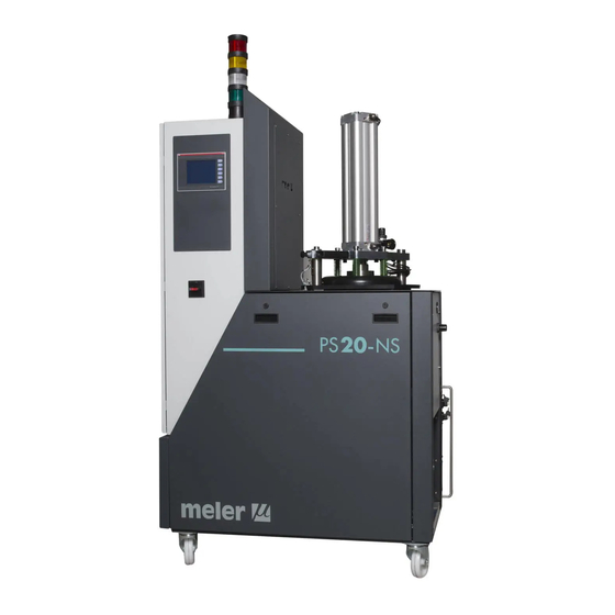
FOCKE MELER GLUING SOLUTIONS INTRODUCTION Main components 1. Touchscreen. 2. Access door to the electronic section and connections. 3. Tank access cover. 4. Main power switch. 5. Electrical connection. 6. Unit transport wheels. 7. Hose-applicator electrical connections. Right side or rear placed. - Page 15 INTRODUCTION MA-5130-GBR PS20 NON STOP DRUM UNLOADER INHIBITION MANUAL...
-
Page 16: Optional Equipment
FOCKE MELER GLUING SOLUTIONS INTRODUCTION Optional equipment To increase the performances of the machine it is possible to improve it with the following options: • Pneumatic by-pass valve pressure control system (VP). • Double pressure solenoid valve control system (DP). -
Page 17: Double Pressure Solenoid Valve Control System (Dp)
INTRODUCTION MA-5130-GBR PS20 NON STOP DRUM UNLOADER INHIBITION MANUAL Double pressure solenoid valve control system (DP) This solenoid valve has two air-inputs and one air-output. When the solenoid valve is not activated, the pressure to the bypass valve is equal to the net pressure supplied to the melter. At the moment this device is activated, air at a regulated pressure is introduced into the bypass valve. - Page 18 FOCKE MELER GLUING SOLUTIONS INTRODUCTION This page is intentionally left blank.
-
Page 19: Installation
Introduction The PS20 Non Stop melters are delivered with all the materials necessary for their installation. However, some components must be provided by the user himself, according to the location and connections in each particular installation: •... -
Page 20: Electrical Consumption
FOCKE MELER GLUING SOLUTIONS INSTALLATION Electrical Consumption In order to install a PS20 Non Stop melter, we should take into consideration the total consumption of the installation, including the consumption of the installed hoses and applicators. Before connecting, make sure that the voltage that is being connected to the melter is the correct one appearing on the equipment’s characteristics plate. -
Page 21: Other Factors
• Connector for external I/O (included on the power card). Mounting the equipment The PS20 Non Stop melting equipment are equipped with wheels for their easy transport and positioning near the main machine. The four wheels turn 360°, and two are equipped with brakes. To move the... -
Page 22: Electrical Power Connection
FOCKE MELER GLUING SOLUTIONS INSTALLATION Electrical power connection PS20 Non Stop melters are designed to be connected to the electrical power supply in one possible way, depending on their power consumption: • 3-phase 400 VAC with neutral. A good ground connection is required in all cases. -
Page 23: Hose And Applicator Connection
Hose and applicator connection PS20 Non Stop melters use standard Meler components. The entire range of Meler hoses and applicators may be connected to this equipment. Up to four hose-applicator outputs may be connected to PS20 Non Stop system melters, depending on the number of pumps installed. -
Page 24: Temperatures Ok
FOCKE MELER GLUING SOLUTIONS INSTALLATION • External Standby_control input from the standby mode, from a non-voltage contact. The standby function is connected with a closed contact; an open contact disconnects it. • Low level_ contact no- voltage output that connects the main machine (or to a warning light tower) the adhesive level in the tank has reached the minimum limit (optional). -
Page 25: External On/Off
INSTALLATION MA-5130-GBR PS20 NON STOP DRUM UNLOADER INHIBITION MANUAL External ON/OFF 1. If only this signal will be connected, use a 0.5 mm two-wire cable. 2. Open the door of the electrical cabinet as far as possible. Thread the power cord (Ø4-8 mm) through the electrical cable gland Pg13, making sure that the cord reaches the terminal blocks where that signal has to be connected. -
Page 26: On/Off Status
FOCKE MELER GLUING SOLUTIONS INSTALLATION 4. Make sure that the cables are firmly attached by the terminal screws. 5. Make sure that the cable is well connected and that its path through the electrical cabinet presents no risks of snagging, being cut or any other accidental deterioration. -
Page 27: Adhesive Bag Empty
INSTALLATION MA-5130-GBR PS20 NON STOP DRUM UNLOADER INHIBITION MANUAL Adhesive bag empty If only this signal will be connected, use a 0.5 mm two-wire cable. 2. Open the door of the electrical cabinet as far as possible. Thread the power cord (Ø4-8 mm) through the electrical cable gland Pg13, making sure that the cord reaches the terminal blocks where that signal has to be connected. -
Page 28: Motor Speed Set Point Reference
FOCKE MELER GLUING SOLUTIONS INSTALLATION 3. Insert the wires in XP11 and XP12 terminal blocks and tighten them with the fixing screws. The terminal block is double so you must to connect every wire in a free hole of the terminal block. It has no polarity so it doesn’t matter the place you connect them. -
Page 29: External Channels Inhibition
INSTALLATION MA-5130-GBR PS20 NON STOP DRUM UNLOADER INHIBITION MANUAL External channels inhibition 1. If only this signal will be connected, use a 0.5 mm two-wire cable. 2. Open the door of the electrical cabinet as far as possible. Thread the power cord (Ø4-8 mm) through the electrical cable gland Pg13, making... - Page 30 FOCKE MELER GLUING SOLUTIONS INSTALLATION This page is intentionally left blank. 3-12...
-
Page 31: Navegation Sur L'ecran Tactile
NAVEGATION SUR L’ECRAN TACTILE MA-5060-FRA MANUEL VIDE FÛTS PS20 NON STOP 4. NAVEGATION SUR L’ECRAN TACTILE L’écran tactile est composé de 5 onglets principaux. Certains onglets principaux permettent à leur tour d’accéder à d’autres écrans. • Onglet A : INTRO – Écran 1 –... - Page 32 FOCKE MELER GLUING SOLUTIONS NAVEGATION SUR L’ECRAN TACTILE A - Intro B - Température interne C - Température externe D - Pompe E - Cuve Vers l’écran 2 Écran 2 Vers l’écran ‘CONF. PROGRAMME’ Vers l’écran ‘CONF. DATE’ Vers l’écran 3 Vers l’écran 1 Écran CONF.
- Page 33 NAVEGATION SUR L’ECRAN TACTILE MA-5060-FRA MANUEL VIDE FÛTS PS20 NON STOP Écran ‘CONF. DATE’ Vers l’écran 2 Écran 3 Vers l’écran 4 Vers l’écran 2 Écran 4 Vers l’écran 5 Vers l’écran 3...
- Page 34 FOCKE MELER GLUING SOLUTIONS NAVEGATION SUR L’ECRAN TACTILE Écran 5 MOT DE PASSE ACTIVÉ Vers l’écran 4 Vers l’écran TºEXT 2...
- Page 35 NAVEGATION SUR L’ECRAN TACTILE MA-5060-FRA MANUEL VIDE FÛTS PS20 NON STOP Vers l’écran TºEXT 1 Vers l’écran 3 Vers l’écran ‘SIGNAL EXTÉRIEUR POMPE 1’ Si l’unité est équipée de deux pompes, ce bouton renvoie à l’écran ‘SIGNAL EXTÉRIEUR POMPE 2’. Écran SIGNAL EXTÉRIEUR POMPE 1 / POMPE 2...
- Page 36 FOCKE MELER GLUING SOLUTIONS NAVEGATION SUR L’ECRAN TACTILE Vers l’écran ‘PRÉFUSION’ Vers l’écran ‘INJECTION GAZ’ Écran ‘PRÉFUSION’ Vers l’écran CUBE Écran INJECTION GAZ Vers l’écran CUBE...
-
Page 37: Configuration De L'unité
NAVEGATION SUR L’ECRAN TACTILE MA-5060-FRA MANUEL VIDE FÛTS PS20 NON STOP Configuration de l’unité Paramètres La machine permet de configurer 10 paramètres: 1. Déconnexion pour cause de température excessive La machine se coupe lorsque la température est supérieure à la température de consigne (valeur de majoration comprise entre 10 et 30). -
Page 38: Activation De La Mise En Veille (Standby) Après Arrêt Du Moteur
FOCKE MELER GLUING SOLUTIONS NAVEGATION SUR L’ECRAN TACTILE 3. Activation de la mise en veille (standby) après arrêt du moteur La machine se met en veille lorsque le moteur n’est pas utilisé pendant une certaine durée. Cette durée est programmable et peut être comprise entre 1 et 60 minutes. -
Page 39: Durée D'injection D'air
NAVEGATION SUR L’ECRAN TACTILE MA-5060-FRA MANUEL VIDE FÛTS PS20 NON STOP 5. Durée d’injection d’air Il s’agit de la durée de séchage du réservoir, à savoir le temps pendant lequel de l’air y est injecté et refoulé. Vers l’écran ‘INJECTION GAZ’... -
Page 40: Délai De Déclenchement De L'alarme D'injection D'air
FOCKE MELER GLUING SOLUTIONS NAVEGATION SUR L’ECRAN TACTILE 7. Délai de déclenchement de l’alarme d’injection d’air Si l’injection d’air est activée et que le couvercle du réservoir s’ouvre, un délai s’écoule jusqu’à ce que l’alarme ne se déclenche (la balise s’allume en rouge). -
Page 41: Délai D'attente
NAVEGATION SUR L’ECRAN TACTILE MA-5060-FRA MANUEL VIDE FÛTS PS20 NON STOP 9. Délai d’attente Si la préfusion est activée et que le détecteur de niveau détecte la présence de colle, le délai d’attente correspond à la durée, en secondes, qui s’écoule entre cette situation et la désactivation de la préfusion. -
Page 42: Programmation De L'horloge
FOCKE MELER GLUING SOLUTIONS NAVEGATION SUR L’ECRAN TACTILE Programmation de l’horloge 1. Programmation du jour de la semaine et de l’heure actuelle. Vers l’écran ‘CONF. DATE’ L’écran ‘DATE ET HEURE’ s’affiche sur le moniteur. Vers le clavier numérique Le clavier numérique s’affiche à l’écran. Saisir une valeur et appuyer sur ‘ENT’. -
Page 43: Programmation De L'activation/Désactivation De L'unité
NAVEGATION SUR L’ECRAN TACTILE MA-5060-FRA MANUEL VIDE FÛTS PS20 NON STOP 2. Programmation de l’activation/désactivation de l’unité Une heure d’activation et une heure de désactivation de l’unité peuvent être programmées pour chaque jour de la semaine. Cette programmation peut être activée ou désactivée par le biais de la touche ON/OFF. -
Page 44: Programmation De L'activation/Désactivation De La Fonction De Mise En Veille (Standby) De L'unité
FOCKE MELER GLUING SOLUTIONS NAVEGATION SUR L’ECRAN TACTILE Pour finir, activer ou désactiver la programmation en appuyant sur l’onglet ON/OFF. Activer Désactiver 3. Programmation de l’activation/désactivation de la fonction de mise en veille (standby) de l’unité Une heure d’activation et une heure de désactivation de l’unité peuvent être programmées pour chaque jour de la semaine. -
Page 45: Exemple De Programmation D'activation, De Désactivation Et De Mise En Veille
NAVEGATION SUR L’ECRAN TACTILE MA-5060-FRA MANUEL VIDE FÛTS PS20 NON STOP Exemple de programmation d’activation, de désactivation et de mise en veille Pour que l’unité fonctionne toutes les semaines selon la séquence suivante : • Lundi ON 09:00 h ->... -
Page 46: Établir Le Mot De Passe De Sécurité
FOCKE MELER GLUING SOLUTIONS NAVEGATION SUR L’ECRAN TACTILE Établir le mot de passe de sécurité Lorsque le mot de passe de l’unité est activé, l’opérateur peut afficher les données de travail des différents écrans du menu, mais il ne peut pas réaliser de modifications. -
Page 47: Établissement Des Températures De Travail
NAVEGATION SUR L’ECRAN TACTILE MA-5060-FRA MANUEL VIDE FÛTS PS20 NON STOP Établissement des températures de travail Pour un bon fonctionnement de l’unité, il s’avère primordial de sélectionner les températures de travail appropriées. Ces températures dépendent du point de ramollissement de la colle. - Page 48 FOCKE MELER GLUING SOLUTIONS NAVEGATION SUR L’ECRAN TACTILE Pour établir la température des applicateurs et des tuyaux, sélectionner l’on- glet ‘T° EXT’. Cet onglet permet d’accéder à l’écran 1 et à l’écran 2. L’écran 1 affiche la température des applicateurs et des tuyaux 1 et 2.
-
Page 49: Contrôle De La Vitesse De La Pompe
NAVEGATION SUR L’ECRAN TACTILE MA-5060-FRA MANUEL VIDE FÛTS PS20 NON STOP La colonne de droite affiche la température réelle, tandis que la colonne de gauche indique la température sélectionnée. Tº programmée T° réelle Appuyer sur le bouton ON/OFF pour activer et désactiver les distributeurs, les applicateurs et les tuyaux. - Page 50 FOCKE MELER GLUING SOLUTIONS NAVEGATION SUR L’ECRAN TACTILE Pour que le système puisse pomper, trois conditions doivent être remplies : 1. L’opérateur doit avoir activé le pompage (option d’activation ON/OFF à l’écran). 2. Les températures présélectionnées pour chaque élément (réservoir, grille, distributeur, applicateurs et tuyaux) doivent avoir été atteintes.
-
Page 51: Sélection Du Signal 'Interne
NAVEGATION SUR L’ECRAN TACTILE MA-5060-FRA MANUEL VIDE FÛTS PS20 NON STOP Sélectionner le signal ON/OFF ‘EXTERNE’. Il est alors possible de sélectionner la consigne interne ou externe. Sélection du signal ‘INTERNE’ Sélectionner ‘INTERNE’. Appuyer pour saisir la valeur de la vitesse. - Page 52 FOCKE MELER GLUING SOLUTIONS NAVEGATION SUR L’ECRAN TACTILE L’écran ‘SIGNAL EXTÉRIEUR POMPE 1 » ou ‘SIGNAL EXTÉRIEUR POMPE 2 » s’affiche. Le tableau contenant les valeurs souhaitées pour toute l’application s’affiche. Une pression sur chaque onglet permet d’afficher le clavier numérique. Saisir une valeur comprise entre 0 et 100 et appuyer sur ‘ENT’.
-
Page 53: Régulation De La Soupape De Dérivation
NAVEGATION SUR L’ECRAN TACTILE MA-5060-FRA MANUEL VIDE FÛTS PS20 NON STOP Régulation de la soupape de dérivation Le système de pompage par pompe à engrenage fournit un débit de colle constant en fonction de la vitesse de rotation de la pompe. -
Page 54: Arrêt De L'unité Centrale
FOCKE MELER GLUING SOLUTIONS NAVEGATION SUR L’ECRAN TACTILE Arrêt de l’unité centrale Pour couper l’unité centrale: 1. Déconnecter l’interrupteur général de l’unité situé sur la façade. 2. Régler la pression de la soupape de dérivation sur 0 (s’il s’agit du modèle à... -
Page 55: Régulation De La Pression De Poussée
NAVEGATION SUR L’ECRAN TACTILE MA-5060-FRA MANUEL VIDE FÛTS PS20 NON STOP Électrovanne Régulateur 1 Régulateur 2 du vérin Électrovannes de refoulement Manomètre Électrovanne Manomètre Clapet de limitation 0,5 bar d'entrée Régulation de la pression de poussée La pression de poussée est contrôlée par le régulateur situé à côté du vérin pneumatique. - Page 56 FOCKE MELER GLUING SOLUTIONS NAVEGATION SUR L’ECRAN TACTILE Cette page n’a pas de texte. 4-26...
-
Page 57: Melter Operation
MELTER OPERATION MA-5130-GBR PS20 NON STOP DRUM UNLOADER INHIBITION MANUAL 5. MELTER OPERATION In this section we will introduce the method for using the melter. Although its operation is very simple, it should not be used by untrained personnel. Warning: Improper use may cause damage to the machine or injury and even death to the person using it. -
Page 58: Filling The Tank
FOCKE MELER GLUING SOLUTIONS MELTER OPERATION Filling the tank The tank can be equipped with a low level sensor (optional) that warns when the level of hot-melt adhesive drops below a third of the tank’s capacity. The unit will activate the external signal and, if it is connected, the corresponding warning device (white colour). -
Page 59: Starting Up The Melter Equipment
MELTER OPERATION MA-5130-GBR PS20 NON STOP DRUM UNLOADER INHIBITION MANUAL 3. Lift lid to activate the touch screen. 4. Unlock (1) and open the lid (2). 5. Take the adhesive block through the bag and introduce it inside the tank. - Page 60 FOCKE MELER GLUING SOLUTIONS MELTER OPERATION It is also necessary to make sure that the equipment has been filled with adhesive and that the operational parameters have been programmed. To start: 1. Connect the melter switch. The touch screen will light up and the display will show “ENTER”. Go to screen 2.
-
Page 61: Alarm Displays
MELTER OPERATION MA-5130-GBR PS20 NON STOP DRUM UNLOADER INHIBITION MANUAL Alarm displays Non Stop melter equipment tell the user when a malfunction has occurred in the unit, sending warning messages that may be seen on the control panel display. Actions... -
Page 62: Premelting Activating
FOCKE MELER GLUING SOLUTIONS MELTER OPERATION When an alarm appears, the control unit takes a series of steps to protect the unit. Simply correct that malfunction and the control unit will reactivate the equipment functions. The light tower system shows the following states: RED: Alarm. -
Page 63: Gas Injection
MELTER OPERATION MA-5130-GBR PS20 NON STOP DRUM UNLOADER INHIBITION MANUAL The screen which allowed enable and disable the premelting appears. Click on the tab to activate it. The fuser grill begins to heat up to set temperature. At the same time the cylinder press with the pressure indicated in the external gauge. - Page 64 FOCKE MELER GLUING SOLUTIONS MELTER OPERATION Click on the tab to activate it. The system begins the injection cycle following the parameters esthablised (Injection time, Waiting time). During melting block, the melted adhesive falls to the down tank. Once the adhesive reached to the level detector, the fuser grid is disconnected and the pneumatic cylinder stops to press.
-
Page 65: Maintenance
The following table briefly summarizes the indications for adequate melter equipment maintenance. Always read the corresponding section carefully. If the equipment does not work or works incorrectly, called to your Meler Representative or to the Main Office. Operation... -
Page 66: Depressurizing The System
5. To replace the panels, follow steps 1 through 3 in the reverse order. Depressurizing the system Melting equipment belonging to the PS20 Non Stop include a safety valve (a by-pass valve) that limits the maximum pressure within the system, especially during continuous pumping periods with closed applicator applicators. -
Page 67: Cleaning Burnt Adhesive
MAINTENANCE MA-5130-GBR PS20 NON STOP DRUM UNLOADER INHIBITION MANUAL 2. Clean the remains of hot-melt adhesive on the inside of the tank. Warning: Use appropriate protective equipment for high temperatures. 3. Add the appropriate type and quantity of the new adhesive, wait for it to melt and pump at least one full tank through the system (hoses and applicators). -
Page 68: Cleaning The Bottom Tank
FOCKE MELER GLUING SOLUTIONS MAINTENANCE 5. Once completely empty, clean the any remaining adhesive from around the output hole and ramp. 6. Replace the plug. 7. Raise the discharge ramp and replace the side shroud cap. Warning: Use appropriate protective equipment for high temperatures. - Page 69 MAINTENANCE MA-5130-GBR PS20 NON STOP DRUM UNLOADER INHIBITION MANUAL 3. Remove the frontal cap. 4. Unscrew the electrical cabinet screws (1) and slide it back (2). 5. Remove 2 screws from the hinge and 4 from the grill- reservoir assembly.
-
Page 70: Cleaning The Platten
FOCKE MELER GLUING SOLUTIONS MAINTENANCE 8. Once the cleaning is done put the front cap again releasing the hinge. 9. Place the screws removed before. 10. Move the front cap screwing the two screw and put the lateral caps. Cleaning the platten 1. - Page 71 MAINTENANCE MA-5130-GBR PS20 NON STOP DRUM UNLOADER INHIBITION MANUAL 5. Remove the plate taking take the tube. 6. Lift the lid. 7. Open the lid till the blocking fastener. 8. Go down the platten. To do so activate the solenoid valve.
-
Page 72: Cleaning The Capacitive Sensor
FOCKE MELER GLUING SOLUTIONS MAINTENANCE Cleaning the capacitive sensor It is necessary to remove any adhesive residue that may remain on the sensor regularly (at least once every three months) to prevent any incorrect level rea- dings. It is also advisable to clean it when cleaning the tank or when changing the type of adhesive. -
Page 73: Verification Of The Sensor Regulation
MAINTENANCE MA-5130-GBR PS20 NON STOP DRUM UNLOADER INHIBITION MANUAL The amplifier that adjusts the sensor´s sensitivity is located in the control cabinet. This amplifier has two states indicated with two different LED colours (1): • Green: no adhesive (empty). Empty Full •... -
Page 74: Pump Maintenance
FOCKE MELER GLUING SOLUTIONS MAINTENANCE Pump maintenance Inspecting for leaks The pump is equipped with a gasket system on the shaft to prevent adhesive from leaking through it. On occasion, some adhesive may leak out, which makes it necessary to retighten the screws or change the gasket. -
Page 75: Recommended Lubricants
MAINTENANCE MA-5130-GBR PS20 NON STOP DRUM UNLOADER INHIBITION MANUAL Recommended lubricants Brand Type of grease Telesia Compound A SHELL Tivela Compound A MOBIL Glygoyle Grease 00 Brand Type of oil KLÜBER Klübersynth GH 6-220 SHELL Tivela Oil S 220 MOBIL... -
Page 76: Air Dryer Filter Maintenance
FOCKE MELER GLUING SOLUTIONS MAINTENANCE Air dryer filter maintenance The filtering elements prior to the air dryer device on the melting equipment are equipped with a filter saturation indicator, which indicates the best time to change the filter cartrtidge: Green colour: Low level of cartridge contamination. -
Page 77: Technical Characteristics
TECHNICAL CHARACTERISTICS MA-5130-GBR PS20 NON STOP DRUM UNLOADER INHIBITION MANUAL 7. TECHNICAL CHARACTERISTICS Generals Tank capacity Ø286 x 395 (20 kg blocks) Reserve tank capacity 3.5L (used) / 10L (max.) Pumping rate (*) single pump 1, 2.5, 4 and 8 cc/rev double pump (per output) 2x0.93, 2x1.86, 2x3.71 and 2x4.8 cc/rev... -
Page 78: Dimensions
FOCKE MELER GLUING SOLUTIONS TECHNICAL CHARACTERISTICS Dimensions 1040 Accesories Pneumatic by-pass valve pressure control system The equipment’s by-pass valve provides an important safety feature, as it limits the maximum pressure in the system, especially during continuous pumping periods with closed applicator guns. -
Page 79: Air Drying System For Pur Adhesives
The PS20 Non-Stop melting equipment ensures a dry environment thanks to the addition of an air-drying system to these models, which provides a level of dehumidification above 99.98%. This guarantees that the adhesive is... - Page 80 FOCKE MELER GLUING SOLUTIONS TECHNICAL CHARACTERISTICS This page is intentionally left blank.
-
Page 81: Electrical Drawings
ELECTRICAL DRAWINGS MA-5130-GBR PS20 NON STOP DRUM UNLOADER INHIBITION MANUAL 8. ELECTRICAL DRAWINGS... - Page 82 FOCKE MELER GLUING SOLUTIONS ELECTRICAL DRAWINGS This page is intentionally left blank.
-
Page 83: Pneumatic Drawing
PNEUMATIC DRAWING MA-5130-GBR PS20 NON STOP DRUM UNLOADER INHIBITION MANUAL 9. PNEUMATIC DRAWING Components list Set air dryer - Filter grade 7 - Filter grade 5 - Dryer Solenoid valve 3/2 Pressure regulator 1-10 bar Pressure gauge 0-10 bar Pressure regulator 0.1-0.7 bar Pressure gauge 0-1.6 bar... - Page 84 FOCKE MELER GLUING SOLUTIONS PNEUMATIC DRAWING...
-
Page 85: Pneumatic By-Pass Valve Pressure Control System (Vp)
PNEUMATIC DRAWING MA-5130-GBR PS20 NON STOP DRUM UNLOADER INHIBITION MANUAL Pneumatic by-pass valve pressure control system (VP) 0 SISTEMA MANUAL DE DOBLE PRESION MICRON Double pressure solenoid valve control system (DP) MANÓMETRO PRESSURE GAUGE ENTRADA DE AIRE AIR INPUT ELECTROVÁLVULA 5/2 REGULADOR DE PRESIÓN... - Page 86 FOCKE MELER GLUING SOLUTIONS PNEUMATIC DRAWING This page is intentionally left blank.
-
Page 87: Spare Parts List
SPARE PARTS LIST MA-5130-GBR PS20 NON STOP DRUM UNLOADER INHIBITION MANUAL 10. SPARE PARTS LIST The most common spare parts list of the Non Stop adhesive melters is shown in this chapter to give you a quick and sure guideline to choose them. - Page 88 FOCKE MELER GLUING SOLUTIONS SPARE PARTS LIST This page is intentionally left blank. 10-2...
-
Page 89: Cover Assembly
SPARE PARTS LIST MA-5130-GBR PS20 NON STOP DRUM UNLOADER INHIBITION MANUAL A. COVER ASSEMBLY Nº Ref. Description 150029770 Cover seal Ø4 lid PS20 Non-stop 150110580 Pusher disc assembly 150029790 Pneumatic cylinder PS20 Non- Stop 150029800 Cover seal Ø25x3 150028100 Open cover blocking fastener... -
Page 90: Tank Group
Nº Ref. Description 150028230 Tank isolation blind valve o-ring 150025460 Tank isolation valve o-ring 150029820 Tank insulation mantle PS20- Non Stop 150110140 Capacitive sensor 150029840 Tank seal Ø4 PS20- Non Stop 150029850 Heating element 630W Ø12.5x250 230V 10030007 Ceramic terminals block 10030009 Safety thermostat 240°C... -
Page 91: Distributor Group
SPARE PARTS LIST MA-5130-GBR PS20 NON STOP DRUM UNLOADER INHIBITION MANUAL C. DISTRIBUTOR GROUP Nº Ref. Description 150027950 Complete two 3/4” hydraulic outputs block 150023950 O-ring Ø24x2 10100082 Pump plug with o-ring 10100083 Pump plug o-ring 150027960 Pump 3/4” plug with o-ring 150041920 Pump 3/4”... -
Page 92: Filter And Pressure Valve Group
FOCKE MELER GLUING SOLUTIONS SPARE PARTS LIST D. FILTER AND PRESSURE VALVE GROUP Nº Ref. Description 150026260 Mechanical pressure valve assembly 150026270 Pneumatic pressure valve assembly (*) 150026280 Mechanical pressure valve o-rings 150026290 Mechanical pressure valve spring 150026060 Pressure valve closure needle... -
Page 93: Motor-Pump Group
SPARE PARTS LIST MA-5130-GBR PS20 NON STOP DRUM UNLOADER INHIBITION MANUAL E. MOTOR-PUMP GROUP Nº Ref. Description 150025960 Single gear pump 1cc/rev seat Ø79 150114020 Single gear pump 2.5cc/rev seat Ø79 150025930 Single gear pump 4cc/rev seat Ø79 150025970 Single gear pump 8cc/rev (Plate seat Ø79) -
Page 94: Electrical Cabinet
Description 150028140 PG 21 cable gland 150119180 PG 13 cable gland 150119640 Touch scrren 3 lenguages 1 pump PS20-NS 2017 (*) 150119670 Touch scrren 3 lenguages 2 pumps PS20-NS 2017 (*) 150113680 Power board 6 outlets 150113670 Power board 2 outlets... - Page 95 SPARE PARTS LIST MA-5130-GBR PS20 NON STOP DRUM UNLOADER INHIBITION MANUAL 19.1 10-9...
- Page 96 FOCKE MELER GLUING SOLUTIONS SPARE PARTS LIST 10-10...
-
Page 97: Pneumatic Group
SPARE PARTS LIST MA-5130-GBR PS20 NON STOP DRUM UNLOADER INHIBITION MANUAL G. PNEUMATIC GROUP Nº Ref. Description 10110031 Pressure regulator 150028400 Solenoid valve 2/2 NA 24V DC 18W 150028380 Relief valve 0.5 bar 1/4’ 150028420 Solenoid valve 3/2 1/8 24V DC 5.4W 150028410 Non return valve H/H 3/8’... -
Page 98: Air Dryer Group (Optional)
FOCKE MELER GLUING SOLUTIONS SPARE PARTS LIST H. AIR DRYER GROUP (OPTIONAL) Nº Ref. Description 150110430 Air dryer assembly with support 150110410 Air dryer NORGREN EXCELON PRO 92 SERIES 150110390 Air filter NORGREN F92C-NND-AT0 150110400 Air filter NORGREN F92G-NNN-AT1 150110060... -
Page 99: Ec Declaration Of Conformity
EC DECLARATION OF CONFORMITY Original Declaration The manufacturer, Focke Meler Gluing Solutions, S.A. Pol. Los Agustinos, c/G, nave D-43 E-31160 Orkoien, Navarra - Spain — Focke Group — declaring that the machinery, Type: Model: Serial Number: fulfils all the relevant provisions of the Directive 2006/42/EC on machinery,... - Page 100 For more information speak with your Focke Meler representative: Focke Meler Gluing Solutions, S.A. Pol. Arazuri-Orkoien, c/B, nº3 A E-31170 Arazuri - Navarra - Spain Phone: +34 948 351 110 info@meler.eu - www.meler.eu Focke Group...
Need help?
Do you have a question about the PS20 and is the answer not in the manual?
Questions and answers