Table of Contents
Advertisement
Quick Links
Advertisement
Table of Contents

Related Manuals for Meler B4 NON-STOP


Summary of Contents for Meler B4 NON-STOP
- Page 1 GLUING SOLUTIONS ADHESIVE INSTRUCTIONS MANUAL MELTER NON-STOP MA-5081-E 030120...
- Page 2 The specifications and information contained in this manual may be modified without prior notice. This manual is a translation of the original that was written by Focke Meler Gluing Solutions, S. A in english language. If there is any discrepancy between the different versions of this manual, the original written in the english language shall prevail.
-
Page 3: Table Of Contents
TABLE OF CONTENTS MA-5081-E B4 NS ADHESIVE MELTER MANUAL TABLE OF CONTENTS 1. SAFETY GUIDELINES General Symbols Mechanical components Electrical components Hydraulic components Pneumatic components Thermal components Materials Noise emission declaration Intended use Limited use 2. INTRODUCTION Description Operating modes Melter identification Main components Control panel... - Page 4 FOCKE MELER GLUING SOLUTIONS TABLE OF CONTENTS Other factors Unpacking Contents Mounting the equipment Electrical power supply connection Pneumatic connection Hose and applicator connection Programming parameters Programming working temperatures Selecting the overheating value Keeping a component on display External I/O connections...
- Page 5 TABLE OF CONTENTS MA-5081-E B4 NS ADHESIVE MELTER MANUAL Disabling the equipment activation/deactivation program 4-10 Programming the activation/deactivation of the equipment’s standby function 4-10 Disabling the equipment standby function program 4-11 Special function buttons 4-12 Pump start-up 4-13 Pumping control 4-13 Starting up the pump control card 4-13...
- Page 6 FOCKE MELER GLUING SOLUTIONS TABLE OF CONTENTS Cleaning the tank Changing adhesive type Cleaning burnt adhesive Emptying the tank Cleaning the tank with cleaning pellets Filter maintenance Pump maintenance Leakage inspection Gear motor maintenance Cleaning the motor fan Checking the lubricant...
- Page 7 TABLE OF CONTENTS MA-5081-E B4 NS ADHESIVE MELTER MANUAL B. DISTRIBUTOR UNIT C. MOTOR- PUMP UNIT D. ELECTRIC PANEL AND AUXILIARY COMPONENTS E. WARNING LIGHT UNIT (OPTIONAL) EC DECLARATION OF CONFORMITY 10-1...
- Page 8 FOCKE MELER GLUING SOLUTIONS TABLE OF CONTENTS This page is intentionally left blank.
-
Page 9: Safety Guidelines
SAFETY GUIDELINES MA-5081-E B4 NS ADHESIVE MELTER MANUAL 1. SAFETY GUIDELINES General The information contained in this section applies not only to everyday equipment operation, but also to any procedure carried out on it, whether for preventive maintenance or in the case of repairs and the replacement of worn out parts. -
Page 10: Mechanical Components
FOCKE MELER GLUING SOLUTIONS SAFETY GUIDELINES Mechanical components The hot-melt installation, which is installed to this device, requires moving parts that can cause damage. Use the equipment correctly, and do not remove the safety guards while the equipment is in operation; prevent the risk of possible entrapment due to moving mechanical parts. -
Page 11: Thermal Components
Safety Information Sheet of the adhesive. Materials Meler systems are designed for use with hot-melt adhesives. They should not be used with any other type of material, and especially not with solvents, which may cause personal injury or damage to internal system components. -
Page 12: Intended Use
Note: Do not modify the equipment or use components that were not supplied by Meler. For any modification of a component of the equipment or part of the installation, you must firstly consult the After-Sales Service... -
Page 13: Introduction
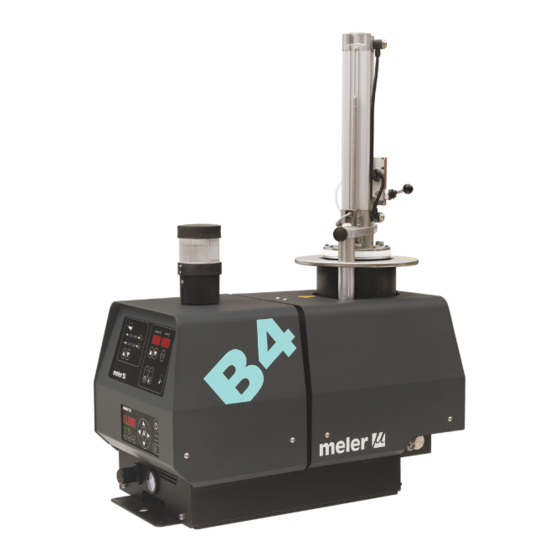
2. INTRODUCTION This manual contains information on installing, using and maintaining the B4 NS adhesive melter from Meler. This equipment is designed to melt 2 kilo blocks of adhesive (Ø128 mm and height 165 mm). It has a 0.45 litre reserve tank. Moreover, in this B4 version with gear pump, speed regulation is possible. -
Page 14: Description
FOCKE MELER GLUING SOLUTIONS INTRODUCTION Description Operating modes The B4 NS melter can be used in the operating modes described below: Operating mode_The melter keeps the hot components at the temperature indicated on the display, which has been preselected as the desired value. The pump-motor unit remains activated while it waits for a consumption request via the opening of one or two application guns. -
Page 15: Melter Identification
INTRODUCTION MA-5081-E B4 NS ADHESIVE MELTER MANUAL adhesive from moisture curing and the block from melting, and stops the already hot air in the melter tank from ascending, possibly inflating the adhesive bag and causing it to expand when the cylinder moves up. Melter identification You will need your melter model and reference when ordering spare parts or requesting support from our Technical Service Centre. -
Page 16: Main Components
FOCKE MELER GLUING SOLUTIONS INTRODUCTION Main components 1. Front control card. 9. Purge valve. 2. Pumping control card. 10. Filter pump. 3. Cylinder air pressure regulator. 11. Hose- applicator hydraulic connection. 4. Cylinder air pressure gauge. 12. Air supply input. -
Page 17: Control Panel
INTRODUCTION MA-5081-E B4 NS ADHESIVE MELTER MANUAL Control panel 1. Tank indicator led. 7. Standby function. 2. Hose indicator led. 8. Temperatures ok led. 3. Applicator indicator led. 9. Timer programming. 4. Temperature set point. 10. Up/Down arrows for element selection. 5. -
Page 18: Pumping Control Card Components
FOCKE MELER GLUING SOLUTIONS INTRODUCTION Pumping control card components 1. Main switch ON/OFF. 2. External start-stop LED. 3. External speed control LED. 4. Pumping permission LED. 5. Up/down arrow keys for selecting values. 6. Left/right arrow keys for selecting options. -
Page 19: Installation
INSTALLATION MA-5081-E B4 NS ADHESIVE MELTER MANUAL 3. INSTALLATION Warning: The melters are equipment with current technology and with certain foreseeable risks. Therefore, only allow qualified personnel with sufficient training and experience to use, install or repair this equipment. Introduction The B4 NS melter is supplied with all the components required for its installation. -
Page 20: Electrical Consumption
FOCKE MELER GLUING SOLUTIONS INSTALLATION Electrical consumption When installing a B4 NS melter, the installation’s total consumption must be taken into account, including the consumption of the installed hose and applicator. Before connecting the melter, make sure that the voltage to which it is to be connected is the same as that indicated on the equipment’s nameplate. -
Page 21: Unpacking
B4 NS ADHESIVE MELTER MANUAL Unpacking Before installing the melter, it should be removed from the pallet and inspected to detect any possible breakage or damage. Notify your Meler Representative or the Main Office of any defect, even to the outer packaging. Contents The B4 NS melter packing materials may contain accessories requested in the same order. -
Page 22: Pneumatic Connection
Hose and applicator connection The B4 NS melter can use standard Meler components. The entire range of Meler hoses and applicators may be connected to this equipment. The B4 NS melter has two outputs for connecting the hose-applicator for only one installed pump. -
Page 23: Programming Parameters
INSTALLATION MA-5081-E B4 NS ADHESIVE MELTER MANUAL Programming parameters Once the melter and its components have been installed, the correct working parameters must be programmed for the specific application to be performed. The B4 NS melter simplifies this task as much as possible, allowing the operator to change only those parameters which are necessarily variable for each application. -
Page 24: Keeping A Component On Display
FOCKE MELER GLUING SOLUTIONS INSTALLATION 3. Use the up-down arrows on the right of the front card to select the desired value. - - - The value displayed corresponds to the increase in real temperature over the set point temperature permitted without activating the alarm message (between 10 and 25). -
Page 25: Temperature Ok
INSTALLATION MA-5081-E B4 NS ADHESIVE MELTER MANUAL • Motor start up_for each pump installed, the motor start up may be controlled by closing an external non-voltage contact. • Motor speed set point_for each pump installed, the rotational speed of the motor (and therefore, the pump) may be controlled by means of a 0 to 10V DC external signal. -
Page 26: Starting Up The Motor (Ok Ext)
FOCKE MELER GLUING SOLUTIONS INSTALLATION 2. Remove the six screws fastening the connection support plate and power switch, on the left side of the equipment. Pass the signal cable (Ø4-8 mm) through the bushing Pg9 and attach to the internal fitting, ensuring that the cable reaches the control board connector at the point where it is to be installed (CN4). -
Page 27: Motor Speed Set Point Reference (Ref Ext)
INSTALLATION MA-5081-E B4 NS ADHESIVE MELTER MANUAL Motor speed set point reference (ref ext) 1. If this is the only signal being connected, use 0.5 mm two-wire cable. Install an electrical wall bushing Pg9 on the equipment base plate next to the electrical supply input. - Page 28 FOCKE MELER GLUING SOLUTIONS INSTALLATION 5. Check that the cable is correctly connected and that its passage through the electric cabinet presents no risk of jamming, being cut or any other accidental damage. Warning: It must be connected to 24 AC or DC voltage with a maximum current of 1A.
-
Page 29: Melter Operation
MELTER OPERATION MA-5081-E B4 NS ADHESIVE MELTER MANUAL 4. MELTER OPERATION This section explains how to operate the melter. Although the equipment is very easy to operate, it should not be used by untrained personnel. Warning: Improper use may cause damage to the equipment itself or the person using it and can even result in death. -
Page 30: Loading The Adhesive Into The Cylindrical Hopper
FOCKE MELER GLUING SOLUTIONS MELTER OPERATION Loading the adhesive into the cylindrical hopper The equipment is equipped with a sensor in the pneumatic cylinder which warns when the block is completely melted (optional system). In this case, the warning light will display an alert to change the block (white light). -
Page 31: Starting Up The Melter
MELTER OPERATION MA-5081-E B4 NS ADHESIVE MELTER MANUAL The B4 NS melter has a tank capacity of 0.45 litres. Starting up the melter Before starting up the equipment, check that the unit is correctly installed and that all the input/output and accessory connections have been established. Also check that the equipment has been filled with the adhesive to be used and that the working parameters have been programmed. -
Page 32: Melter Displays
FOCKE MELER GLUING SOLUTIONS MELTER OPERATION Melter displays The control panel on the B4 NS melters have two displays, each with three sets of 7 segments to display the temperature values (set point and actual temperature), the programmable parameters and alarms. -
Page 33: Temperature Display For Each Component
MELTER OPERATION MA-5081-E B4 NS ADHESIVE MELTER MANUAL Temperature display for each component The temperature of each component (tank and each hose and applicator) can be displayed by selecting the component using the cursors. Press the component selection up/down arrow until the desired component is displayed. -
Page 34: Display And Adjustment Of The Cylinder Working Temperature
FOCKE MELER GLUING SOLUTIONS MELTER OPERATION Display and adjustment of the cylinder working temperature In this equipment, the air pressure with which the pusher cylinder pneumatic control device operates is shown on the pressure gauge located on the base of the melter. The pressure must be adjusted to the requirements of the application. -
Page 35: Programming The Melter Parameters
MELTER OPERATION MA-5081-E B4 NS ADHESIVE MELTER MANUAL Programming the melter parameters 1. Simultaneously press the buttons with the clock symbol and down arrow to enter the special menu. The choice of temperature display units (°C or °F) appear on the display. -
Page 36: Setting The Clock
FOCKE MELER GLUING SOLUTIONS MELTER OPERATION Setting the clock The B4 NS melter has a weekly programmable system to control the connection and disconnection of the equipment and activate and deactivate the standby function. Before programming these functions, the day and time the system will use to execute these programs must be entered into the control panel. -
Page 37: Programming Equipment Activation/Deactivation
MELTER OPERATION MA-5081-E B4 NS ADHESIVE MELTER MANUAL Programming equipment activation/deactivation An activation and deactivation time can be set for each day of the week, from Monday (1) to Sunday (7). Time is expressed in increments of 15 minutes, starting with 10.0 (10 hours 0 minutes), then 10.1 (10 hours 15 minutes), 10.2 (10 hours 30 minutes) and 10.3 (10 hours 45 minutes). -
Page 38: Disabling The Equipment Activation/Deactivation Program
FOCKE MELER GLUING SOLUTIONS MELTER OPERATION Disabling the equipment activation/deactivation program The programmed equipment activation/deactivation can be disabled without having to cancel the daily programming. In this way the programmed data is saved but the programming has no effect on the equipment. -
Page 39: Disabling The Equipment Standby Function Program
MELTER OPERATION MA-5081-E B4 NS ADHESIVE MELTER MANUAL 3. Use the up-down button under the display to select the value for the desired day of the week, Monday (1) to Sunday (7). 4. Press the button with the clock symbol again. 0 7 . -
Page 40: Special Function Buttons
FOCKE MELER GLUING SOLUTIONS MELTER OPERATION O F F O F F 3. Use the up-down arrow under the display to skip past the selection for the last day of the week (7). ‘ON/OFF’ will be displayed depending on the current status. -
Page 41: Pump Start-Up
MELTER OPERATION MA-5081-E B4 NS ADHESIVE MELTER MANUAL If the period of inactivity is more than 1 hour but less than 2 hours, use the standby function. If the period of inactivity is more than 2 hours, turn off the equipment. However, take into consideration that PUR adhesive undergoes moisture curing and deteriorates easily at high temperatures and therefore the more time the equipment is left on without pumping, regardless of whether it is left... -
Page 42: Pumping Safety Measures
FOCKE MELER GLUING SOLUTIONS MELTER OPERATION Pumping safety measures To prevent the equipment from starting up unexpectedly, the control panel features by default a safety option that prevents pumping from commencing until enabled by pressing the ON-OFF button on the control card. This function may be disabled in the ‘User configuration menu’. -
Page 43: Led Indicators
MELTER OPERATION MA-5081-E B4 NS ADHESIVE MELTER MANUAL menu’, on pressing any key (except the control card ON/OFF and pumping ON/OFF buttons) a password will be required. When the password is entered correctly, the control card can be left operational by setting it to ‘0’. When using this method to access the control card security configuration options, i.e., when the password has been entered, the buttons on the control card are temporarily unprotected until one minute has elapsed during which no... -
Page 44: Modes Of Operation
FOCKE MELER GLUING SOLUTIONS MELTER OPERATION 5. Ext on LED: when the equipment is operating in external start-stop (OK) mode, and the external permission contact is closed, this LED will be illuminated; if the external contact is open, this LED is turned off. This LED is green in colour. -
Page 45: Mode Of Operation With Internal Pumping Control And External Speed Control
MELTER OPERATION MA-5081-E B4 NS ADHESIVE MELTER MANUAL The pump will stop whenever: • The control card is disabled with its ON/OFF button. • The pumping ON-OFF button is pressed (red LED is illuminated). • When a variator error signal is activated (E5). •... -
Page 46: Mode Of Operation With External Pumping Control And Internal Speed Control
FOCKE MELER GLUING SOLUTIONS MELTER OPERATION 3. Modify the speed ramp (see section ‘Configuring speed ramp’). Keeping the ‘Vin’ key pressed will show the voltage sent by the main machine. The pump will stop whenever: • The control card is disabled with its ON/OFF button. -
Page 47: Mode Of Operation With External Pumping Control And External Speed Control
MELTER OPERATION MA-5081-E B4 NS ADHESIVE MELTER MANUAL 3. Using the up/down arrows, select the rotation speed and/or wait for pumping permission to be enabled (red LED is turned off). At this moment, the pump will start to rotate at the speed indicated on the display. - Page 48 ‘User configuration menu’, ‘1. MAXIMUM RPM’. The pump control card is designed with certain parameters programmed at Meler that can be modified if necessary to meet your requirements. Modifications may be made through the user configuration and programming speed ramp menus.
-
Page 49: User Configuration Menu
MELTER OPERATION MA-5081-E B4 NS ADHESIVE MELTER MANUAL User configuration menu To open this menu, press simultaneously the left arrow key, the right arrow key, and ON/OFF button of the pump control card. If the security password is enabled, the security password must be entered to access this menu. -
Page 50: Minimum Rpm Alarm
FOCKE MELER GLUING SOLUTIONS MELTER OPERATION Minimum rpm alarm This alarm will be triggered when the motor rotates at a speed that is below the MINIMUM RPM ALARM for the period established in the MINIMUM RPM ALARM TIME field. • When this alarm is triggered, an ‘E.L.’ error is shown on the control card. -
Page 51: Programming Speed Ramp
MELTER OPERATION MA-5081-E B4 NS ADHESIVE MELTER MANUAL • The value for voltage must always be shown to one decimal place. • Point 1 is the starting point for the speed ramp, and therefore the voltage will always be 0, while the value for output RPM is editable. •... -
Page 52: Current Vin Voltage Display
FOCKE MELER GLUING SOLUTIONS MELTER OPERATION The IN LED to the position ON and the OUT LED to the position OFF, 3 XXX, which means that the input voltage value is being programmed for point 3; with the up/down arrow keys the value may be modified, within a range from 00.0 to 10.0 (to one decimal place);... -
Page 53: Adjusting The Manual Valve
MELTER OPERATION MA-5081-E B4 NS ADHESIVE MELTER MANUAL For safety reasons, this pressure must be discharged when the circuit exceeds the working value -normally with the circuit closed and the pump activated- which requires the use of a discharge or bypass valve. This valve may be a manual adjustment valve, using a threaded allen head screw, or with pneumatic control, using a pressure regulator and a pressure gauge. - Page 54 FOCKE MELER GLUING SOLUTIONS MELTER OPERATION This page is intentionally left blank. 4-26...
-
Page 55: Maintenance
Equipment change - Equipment change or repair Dettaching equipment from base If the equipment does not work or works incorrectly, called to your Meler Technical Assistance Service or to the Main Office. External cleaning To continue to take advantage of the melters benefits and to ensure the perfect mobility of its components, it is necessary to keep all its parts clean, especially the ventilation grates on the of the machine. -
Page 56: System Depressurisation
FOCKE MELER GLUING SOLUTIONS MAINTENANCE Removing the rear covers from the melter cylinder: 1. Disconnect the melter using the circuit breaker. 2. Remove the six screws fastening the cover to the melter unit. 3. Remove the cover, sliding it outwards in the direction shown in the figure. -
Page 57: Cleaning The Tank
MAINTENANCE MA-5081-E B4 NS ADHESIVE MELTER MANUAL Before disconnecting any hydraulic component or opening any distributor outlet, the following steps must be performed: 1. Disconnect the equipment’s power switch located on the side, next to the power supply input. 2. Manually purge (or using the corresponding programmer control) the applicator used. -
Page 58: Emptying The Tank
FOCKE MELER GLUING SOLUTIONS MAINTENANCE 2. Clean the adhesive remains and carbon deposit from the inside. Do not use sharp objects which could damage the interior. Warning: Use the appropriate protective equipment for high temperatures. 3. Add the new block of adhesive and wait for it to melt. -
Page 59: Filter Maintenance
MAINTENANCE MA-5081-E B4 NS ADHESIVE MELTER MANUAL 2. To accelerate the fusion of the pellets, rise the melt temperature. 3. Once the pellets are melted, pumping the adhesive through the cleaning circuit. Warning: Use the appropriate protective equipment for high temperatures. 4. -
Page 60: Pump Maintenance
Replace the gasket system in the shaft or the gaskets in the seating pump and reassemble. However, before making any changes and in case of doubt should check with the Technical Assistance Service of Meler. Warning: Always wear protective gloves and safety glasses. Risk of burns. Gear motor maintenance Cleaning the motor fan Regularly check the condition of the motor fan and its vent grid. -
Page 61: Recommended Lubricant
MAINTENANCE MA-5081-E B4 NS ADHESIVE MELTER MANUAL Only use lubricants recommended by the manufacturer. Other types of lubricants may cause premature wear or damage the gear. Approximately 0.10 kg of lubricating grease fits into the gear model used. Recommended lubricant Grasa Kluber, Staburags NBU 12/300. - Page 62 FOCKE MELER GLUING SOLUTIONS MAINTENANCE This page is intentionally left blank.
-
Page 63: Technical Characteristics
TECHNICAL CHARACTERISTICS MA-5081-E B4 NS ADHESIVE MELTER MANUAL 6. TECHNICAL CHARACTERISTICS General Format and type of adhesive EVA/PUR block 2 Kg-Ø128 mm - height 165 mm Maximum viscosity of adhesive up to 45,000 cps Maximum pump flow rate (*) between 1,2 and 15,6 Kg/hr with 2 cc/rev pump Maximum melting rate (*) 5 Kg/h Pressure applied on the block... -
Page 64: Dimensions
FOCKE MELER GLUING SOLUTIONS TECHNICAL CHARACTERISTICS Dimensions Melting unit Base plate * For ML-240-ST series replacement. Accessories Level control system The adhesive level is controlled using an inductive sensor which triggers an alarm signal via a warning light. -
Page 65: Electrical Drawings
ELECTRICAL DRAWINGS MA-5081-E B4 NS ADHESIVE MELTER MANUAL 7. ELECTRICAL DRAWINGS... - Page 66 FOCKE MELER GLUING SOLUTIONS ELECTRICAL DRAWINGS This page is intentionally left blank.
-
Page 67: Pneumatic Drawings
PNEUMATIC DRAWINGS MA-5081-E B4 NS ADHESIVE MELTER MANUAL 8. PNEUMATIC DRAWINGS Components list Pneumatic cylinder control system Inlet filter (filtering disk). Pressure regulator. Pressure gauge. Pneumatic valve 5/2. Pneumatic cylinder. Exhaust port filter. -
Page 68: Pneumatic By-Pass Valve Control System (Optional)
FOCKE MELER GLUING SOLUTIONS PNEUMATIC DRAWINGS Pneumatic by-pass valve control system (optional) Pressure regulator 1-10 bar Pressure gauge 0-10 bar Pneumatic limit control valve AIR INPUT... -
Page 69: Spare Part List
SPARE PART LIST MA-5081-E B4 NS ADHESIVE MELTER MANUAL 9. SPARE PART LIST The most common spare parts list of the B4 NS adhesive melters is shown in this chapter to give you a quick and sure guideline to choose them. The spare parts are listed by groups in a natural order as they are located on the units. - Page 70 FOCKE MELER GLUING SOLUTIONS SPARE PART LIST This page is intentionally left blank.
-
Page 71: Tank Group
SPARE PART LIST MA-5081-E B4 NS ADHESIVE MELTER MANUAL A. TANK GROUP Nº Ref. Description 150113740 Cylinder ISO-VDMA 24562 150113750 O-ring for empty tank cover 150113760 Cylinder-tank o-ring 150113770 Manual valve 150113780 300W tank heating element 150113820 750W tank heatin element 10030007 Current connection strip 150028100... -
Page 72: Distributor Unit
FOCKE MELER GLUING SOLUTIONS SPARE PART LIST B. DISTRIBUTOR UNIT Nº Ref. Descriptionn 150113810 Relief valve assembly 12330087 Relief valve assembly o-ring 150112820 Relief valve spring 150026060 Relief valve closing needle 150090390 Relief valve seeger ring 150090360 Tank-distributor seating o-ring... -
Page 73: Motor- Pump Unit
SPARE PART LIST MA-5081-E B4 NS ADHESIVE MELTER MANUAL C. MOTOR- PUMP UNIT Nº Ref. Description 150026110 2cc/rev gear pump 150090410 Pump seating o-rings R0007984 Gasket system in the shaft 150026090 Motor coupling 150026080 Geared motor ratio 43,39:1 150026100 Geared motor support 1.1 1.2... -
Page 74: Electric Panel And Auxiliary Components
FOCKE MELER GLUING SOLUTIONS SPARE PART LIST D. ELECTRIC PANEL AND AUXILIARY COMPONENTS Nº Ref. Description 10000204 Control card 150112410 Fuse 6,3A 5x20 ultra fast 150115650 Fuse 10A 6x32 ultra fast 150117100 Pumping control card 10110031 Pressure regulator 150113840 Pressure gauge... -
Page 75: Warning Light Unit (Optional)
SPARE PART LIST MA-5081-E B4 NS ADHESIVE MELTER MANUAL E. WARNING LIGHT UNIT (OPTIONAL) Nº Ref. Description 150110170 Inductive detector 150113710 Colourless warning light R0006220 Lamp 24V 150090430 24V AC 2- contact relay... - Page 76 FOCKE MELER GLUING SOLUTIONS SPARE PART LIST This page is intentionally left blank.
-
Page 77: Ec Declaration Of Conformity
EC DECLARATION OF CONFORMITY Original Declaration The manufacturer, Focke Meler Gluing Solutions, S.A. Pol. Arazuri-Orkoien, c/B, nº3 A E-31170 Arazuri - Navarra - Spain — A Focke Group Company — declaring that the machinery, Type: Model: Serial Number: fulfils all the relevant provisions of the Directive 2006/42/EC on machinery,... - Page 78 For more information speak with your Focke Meler representative: Focke Meler Gluing Solutions, S.A. Pol. Arazuri-Orkoien, c/B, nº3 A E-31170 Arazuri - Navarra - Spain Phone: +34 948 351 110 info@meler.eu - www.meler.eu A Focke Group Company...
Need help?
Do you have a question about the B4 NON-STOP and is the answer not in the manual?
Questions and answers