
Related Manuals for Meler PS200


Summary of Contents for Meler PS200
- Page 1 GLUING SOLUTIONS ADHESIVE INSTRUCTIONS MANUAL MELTER PS200 DRUM UNLOADER MA-5066-ENG 250220...
- Page 2 The specifications and information contained in this manual may be modified without prior notice. This manual is a translation of the original that was written by Focke Meler Gluing Solutions, S. A in english language. If there is any discrepancy between the different versions of this manual, the original written in the english language shall prevail.
-
Page 3: Table Of Contents
TABLE OF CONTENTS MA-5066-ENG PS200 DRUM MELTER MANUAL TABLE OF CONTENTS 1. SAFETY GUIDELINES General Symbols Mechanical components Electrical components Hydraulic components Pneumatic components Thermal components Materials Noise emission declaration Intended use Limited use 2. INTRODUCTION Description Intended use Limited use... - Page 4 FOCKE MELER GLUING SOLUTIONS TABLE OF CONTENTS 3. INSTALLATION Introduction Installation requirements Free space Electrical Consumption Compressed air Other factors Unpacking Contents Equipment placement Electrical power connection Pneumatic connection Hoses and applicators connection Parameter Programming Programming working temperatures Selecting the overheating value...
- Page 5 TABLE OF CONTENTS MA-5066-ENG PS200 DRUM MELTER MANUAL Displaying the temperature for each component Alarm displays Display and adjustment of the working speed Temperature adjustment Programming the applicator parameters Timer to switch between ON - Standby - OFF modes 4-10...
- Page 6 FOCKE MELER GLUING SOLUTIONS TABLE OF CONTENTS Variator alarm 4-26 Configuring speed ramp 4-27 Programming speed ramp 4-28 Current Vin voltage display 4-29 By-pass valve regulation 4-29 Pneumatic valve adjustment 4-29 Placing a new drum 4-30 Removing the empty drum...
- Page 7 TABLE OF CONTENTS MA-5066-ENG PS200 DRUM MELTER MANUAL 8. PNEUMATIC DIAGRAMS Pneumatic drawing with manual aereation system Pneumatic drawing with automatic aereation system 9. SPARE PARTS LIST A. STRUCTURE A. STRUCTURE B. PLATEN ENSEMBLE B. PLATEN ENSEMBLE C. SIMPLE MANIFOLD ENSEMBLE C.
- Page 8 FOCKE MELER GLUING SOLUTIONS TABLE OF CONTENTS This page is intentionally left blank.
-
Page 9: Safety Guidelines
SAFETY GUIDELINES MA-5066-ENG PS200 DRUM MELTER MANUAL 1. SAFETY GUIDELINES General The information contained in this section applies not only to everyday equipment operation, but also to any procedure carried out on it, whether for preventive maintenance or in the case of repairs and the replacement of worn out parts. -
Page 10: Mechanical Components
FOCKE MELER GLUING SOLUTIONS SAFETY GUIDELINES Mechanical components The hot-melt installation, which is installed to this device, requires moving parts that can cause damage. Use the equipment correctly, and do not remove the safety guards while the equipment is in operation; prevent the risk of possible entrapment due to moving mechanical parts. -
Page 11: Thermal Components
Safety Information Sheet of the adhesive. Materials Meler systems are designed for use with hot-melt adhesives. They should not be used with any other type of material, and especially not with solvents, which may cause personal injury or damage to internal system components. -
Page 12: Intended Use
Note: Do not modify the equipment or use components that were not supplied by Meler. For any modification of a component of the equipment or part of the installation, you must firstly consult the After-Sales Service... -
Page 13: Introduction
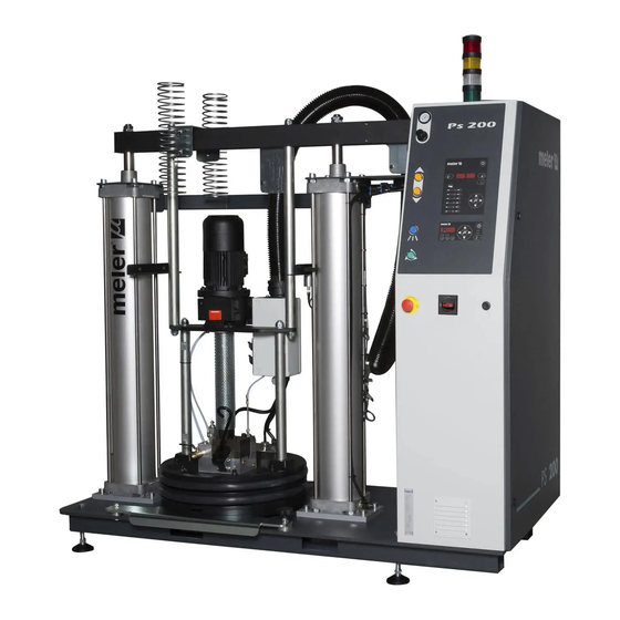
PS200 DRUM MELTER MANUAL 2. INTRODUCTION Description Meler PS200 drum melters are melting and pumping systems for thermoplastic materials that directly use their drum containers (with straight sides) for capacities of up to 200 L. They are designed to be used for applications that require high flow levels and speed in supplying the material to the substrate. -
Page 14: Intended Use
External connection for the ‘temperatures ok’ and ‘empty drum’ signals. PS200 drum melters are designed to be used with Meler hoses and applicators in hot-melt adhesive applications. Their diverse variations - line, coating or swirl-spray - cover a wide range of applications, and are very versatile within all the markets where they are used. -
Page 15: Limited Use
MA-5066-ENG PS200 DRUM MELTER MANUAL Limited use PS200 drum melters must be used in the manner in which they are intended, and never under the following conditions: • Used with materials that may represent safety or health hazards when heated. -
Page 16: Identifying The Melting Equipment
FOCKE MELER GLUING SOLUTIONS, S.A. INTRODUCTION Identifying the melting equipment When ordering replacement parts or requesting assistance from our technical support department, you must know your melting equipment’s model and reference numbers. This and other technical information may be found on the identification plate, located on the frontal side of the electrical cabinet. -
Page 17: Control Panel
INTRODUCTION MA-5066-ENG PS200 DRUM MELTER MANUAL Control panel 1. ‘Platen up’ illuminated pushbutton. 2. ‘Platen down’ illuminated pushbutton. 3. Emergency stop button. 4. Drum aeration pushbutton (‘Air in’). 5. Green ‘Start pump’ pushbutton. 6. Platen down bimanual pushbutton. 7. Main power switch. -
Page 18: Platen Up-Down Pushbuttons
FOCKE MELER GLUING SOLUTIONS, S.A. INTRODUCTION Platen up-down pushbuttons Down BLINKING LIGHT motion allowed motion allowed LIGHT ON actual sense of motion actual sense of motion extreme position reached extreme position reached, but blinks due to empty LIGHT OFF drum signal Four colors light tower RED: Alarms. -
Page 19: Control Card Components
INTRODUCTION MA-5066-ENG PS200 DRUM MELTER MANUAL Control card components 1. Melting platen indicator LED. 2. Applicator indicator LED. 3. Temperature set point. 4. Real temperature. 5. ON/OFF switch. 6. Standby function. 7. Temperature OK LED. 8. Time scheduling. 9. Left/right button - channel selection. -
Page 20: Pumping Control Card Components
FOCKE MELER GLUING SOLUTIONS, S.A. INTRODUCTION Pumping control card components 1. Main switch ON/OFF. 2. External start-stop LED. 3. External speed control LED. 4. Pumping permission LED. 5. Up/down arrow keys for selecting values. 6. Left/right arrow keys for selecting options. -
Page 21: Pneumatic Control
INTRODUCTION MA-5066-ENG PS200 DRUM MELTER MANUAL Pneumatic control The pneumatic control includes solenoid valve for up-down platen movement and drum aeration system. 1. Intake filter. 2. Pneumatic cylinder pressure regulator. 3. Pneumatic cylinder pressure gauge. 4. Bypass valve pressure regulator. -
Page 22: Optional Equipment
FOCKE MELER GLUING SOLUTIONS, S.A. INTRODUCTION Drum aeration pressure regulator adjusts air pressure to refill the empty drum while the platen is been raised up. It is very important to adjust this pressure with the necessary value: a pressure greater than needed may pressurize the drum and cause a certain explosion when the platen goes outside the drum;... -
Page 23: Installation
Introduction PS200 drum melters are delivered with all the materials necessary for their installation. However, some components must be provided by the user himself, according to the location and connections in each particular installation: •... -
Page 24: Electrical Consumption
Compressed air In order to install PS200 drum melters, it is necessary to have a dry, non- lubricated compressed air supply at a maximum pressure of 6 bar. The air intake connection is installed for a pipe with an outside diameter of 12... -
Page 25: Other Factors
Before beginning to install the drum melter, it must be removed from its position on the pallet and inspected in order to detect any possible deterioration or damage. Inform your Meler agent or the Head Office of any defect, including that to the outside packing materials. -
Page 26: Electrical Power Connection
FOCKE MELER GLUING SOLUTIONS, S.A. INSTALLATION Electrical power connection PS200 drum melters are delivered ready to be connected to a 3-phase, 400 VAC 50Hz electrical power supply with a neutral connection, according to its power consumption. A good ground connection is always essential. -
Page 27: Hoses And Applicators Connection
PS200 has a hydraulic manifold with 3 available connections. If you connect only one hose do it in order to facilitate the installation and the connection of the hose. -
Page 28: Selecting The Overheating Value
FOCKE MELER GLUING SOLUTIONS, S.A. INSTALLATION • 160 °C (320 °F) for the melting platen. • 150 °C (302 °F) for hoses and 160 ºC (320 °F) for applicators. The general process for modifying set up temperature values for any component is described below. -
Page 29: Keeping A Component On Display
INSTALLATION MA-5066-ENG PS200 DRUM MELTER MANUAL Keeping a component on display By default, the main display shows the melting platen temperatures. However, it is possible to display indefinitely the temperatures of any component for analysis or tracking. 1. Select the component you wish to see permanently with the left-right arrow. -
Page 30: Temperature Ok
FOCKE MELER GLUING SOLUTIONS, S.A. INSTALLATION - Drum melter ready (temperatures OK-green). - Motor running (pump rotation -amber). - Half empty drum (blinking white). - Empty drum (fixed white). - Alarms (red). Also it is possible to connect this signals to the main machine through non- voltage external contacts. -
Page 31: Output Inhibitor
INSTALLATION MA-5066-ENG PS200 DRUM MELTER MANUAL contact NO contact NO 4. Reconnect the card connector. 5. Make sure that the cable is well connected and that its path through the electrical cabinet presents no risks of snagging, being cut or any other accidental deterioration. -
Page 32: Starting Up The Motor (Ok Ext)
FOCKE MELER GLUING SOLUTIONS, S.A. INSTALLATION Starting up the motor (ok ext) 1. If this is the only signal being connected, use 0.5 mm two-wire cable. 2. Thread the power cord (max. Ø12.5mm) through the electrical wall bushing Pg16 and fasten it to the inside anchor, making sure that the cord reaches the power card connector. -
Page 33: Light Tower Signals
INSTALLATION MA-5066-ENG PS200 DRUM MELTER MANUAL 2. Thread the power cord (max. Ø12.5mm) through the electrical wall bushing Pg16 and fasten it to the inside anchor, making sure that the cord reaches the power card connector. 3. Connect the two wires from the start-up signal to the terminals XE11 and XE12. - Page 34 FOCKE MELER GLUING SOLUTIONS, S.A. INSTALLATION This page is intentionally left blank. 3-12...
-
Page 35: Melter Operation
MELTER OPERATION MA-5066-ENG PS200 DRUM MELTER MANUAL 4. MELTER OPERATION In this section we will introduce the method for using the melter. Although its operation is very simple, it should not be used by untrained personnel. Warning: Improper use may cause damage to the machine or injury and even death to the person using it. -
Page 36: Starting Up The Melter Equipment
FOCKE MELER GLUING SOLUTIONS, S.A. MELTER OPERATION Starting up the melter equipment Before starting up the melter equipment, it is necessary to check to see if the unit has been correctly installed and all its input/output and accessory connections are correctly established. -
Page 37: Melter Equipment Displays
MA-5066-ENG PS200 DRUM MELTER MANUAL Melter equipment displays PS200 drum melters have two displays built into their control panel, with three sets of 7 segments each for displaying the temperature values (set point and real temperature), programmable parameters and alarms. -
Page 38: Displaying The Temperature For Each Component
FOCKE MELER GLUING SOLUTIONS, S.A. MELTER OPERATION Displaying the temperature for each component The temperature may be displayed for each component (platen, each hose and applicator) by selecting the component with the cursor. Press the left-right arrow until the desired component is displayed. -
Page 39: Display And Adjustment Of The Working Speed
MELTER OPERATION MA-5066-ENG PS200 DRUM MELTER MANUAL Code Source Actions Heating Pump Main machine signal platen broken sensor only platen off hose1 broken sensor only hose1 off applicator1 broken sensor only applicator1 off hose2 broken sensor only hose2 off applicator2 broken sensor... -
Page 40: Programming The Applicator Parameters
FOCKE MELER GLUING SOLUTIONS, S.A. MELTER OPERATION • Overheating value: 25°C. • Standby value: 40%. • Delay time: 10 min. • Timetable programs: OFF. The general process for adjusting the temperatures of each components is described below. 1. Select the component whose value you wish to modify using the left- right arrow. - Page 41 MELTER OPERATION MA-5066-ENG PS200 DRUM MELTER MANUAL Modify value To select the function to be programmed, press the right arrow to advance through the various functions. Once selected, the buttons up and down modify the value. Pressing the arrow right again the data is stored and passed to the...
- Page 42 FOCKE MELER GLUING SOLUTIONS, S.A. MELTER OPERATION 9. Use the right arrow to advance to the next screen, where the level detector activation/deactivation is found. 10. Use the up-down arrow to select the desired value (ON/OFF). When OFF is selected, neither the on-screen display nor the external signal activation will be operational.
- Page 43 MELTER OPERATION MA-5066-ENG PS200 DRUM MELTER MANUAL 18. Use the right arrow to go to the next display. 19. Use the up-down arrow to select the desired value (see ‘Counter that warns of the need to change the adhesive agent filter’).
-
Page 44: Timer To Switch Between On - Standby - Off Modes
FOCKE MELER GLUING SOLUTIONS, S.A. MELTER OPERATION Timer to switch between ON - Standby - OFF modes This function is used to program automatic switching from the ON mode to Standby mode after an inactive period of time (S-1) and from STANDBY mode to OFF mode after another waiting period (S-2) during which activity has not been resumed. -
Page 45: Password To Access Parameter Programming
MELTER OPERATION MA-5066-ENG PS200 DRUM MELTER MANUAL Password to access parameter programming A Password can be programmed to protect access to certain equipment pro- gramming functions by unauthorised users. The special menu can be used to program a value between 000 (disabled) and 999. -
Page 46: Counter That Warns Of The Need To Change The Adhesive Agent Filter
FOCKE MELER GLUING SOLUTIONS, S.A. MELTER OPERATION Counter that warns of the need to change the adhesive agent filter This function is a partial countdown counter that registers the hours of equi- pment operation, that is, with service temperature OK activated, from tP1000 hours to tP0000 hours. -
Page 47: Setting The Clock
MA-5066-ENG PS200 DRUM MELTER MANUAL Setting the clock PS200 drum melters are equipped with a weekly programmable system controlling equipment connection and disconnection and activating and deactivating the standby function. Before programming these functions, it is necessary to introduce into the control unit data corresponding to the day and hour used to execute these programs. -
Page 48: Programming Equipment Activation/Deactivation
FOCKE MELER GLUING SOLUTIONS, S.A. MELTER OPERATION Programming equipment activation/deactivation You may program an activation and a deactivation time for every day of the week, from Monday (1) to Sunday (7). Time is expressed in 15 minute increments, so we cycle from 10.0 (10 hours and 0 minutes) to 10.1 (10 hours and 15 minutes) to 10.2 (10 hours and 30... -
Page 49: Disabling The Equipment Activation/Deactivation Program
MELTER OPERATION MA-5066-ENG PS200 DRUM MELTER MANUAL Disabling the equipment activation/deactivation program It is possible to disable the equipment activation/deactivation programming without canceling the daily programming. This way the programmed data is saved, but the programming will have no effect on the equipment. -
Page 50: Disabling The Equipment Standby Function Programming
FOCKE MELER GLUING SOLUTIONS, S.A. MELTER OPERATION 4. Press the button with the clock symbol once again. Two times will appear, one in each display. The left display shows the start time, while the right display shows the finish time. -
Page 51: Special Function Buttons
Special function buttons The simplicity of programming PS200 drum melters reduces the use of the special function buttons to only the standby function. This manual function allows you to alternate between the operational mode and the standby mode. -
Page 52: Pumping Control
FOCKE MELER GLUING SOLUTIONS, S.A. MELTER OPERATION Pumping control Starting up the pump control card The pump control card (hereingafter also control card), features an ON-OFF button that allows us to turn off the displays and LEDs (leaving on only the 24... -
Page 53: Password Security
MELTER OPERATION MA-5066-ENG PS200 DRUM MELTER MANUAL When pumping safety is disabled: • In the event of loss of 24 Vdc power supply or the control is turned off with the control card ON-OFF button, on recovering the power supply or... -
Page 54: Led Indicators
FOCKE MELER GLUING SOLUTIONS, S.A. MELTER OPERATION LED indicators Described below are the LED indicators on the pump control card to identify the status of the equipment: 1. Control card ON/OFF LED: when the external 24 Vdc power supply is present, this LED will always be illuminated;... -
Page 55: Modes Of Operation
MELTER OPERATION MA-5066-ENG PS200 DRUM MELTER MANUAL Modes of operation First of all, we must bear in mind that when password security is enabled and the control card is not manipulated during one minute, it is blocked and you need to enter the password. To prevent this from happening, password security may be disabled following the steps in the section ‘Password security’. -
Page 56: Mode Of Operation With Internal Pumping Control And External Speed Control
FOCKE MELER GLUING SOLUTIONS, S.A. MELTER OPERATION Mode of operation with internal pumping control and external speed control In this operating mode, pumping is controlled from the equipment and speed is controlled by a 0-10 V external signal from the main machine. -
Page 57: Mode Of Operation With External Pumping Control And Internal Speed Control
MELTER OPERATION MA-5066-ENG PS200 DRUM MELTER MANUAL Mode of operation with external pumping control and internal speed control In this operating mode, pumping is controlled from the main machine while speed is controlled from the equipment. Follow the steps below to use this operating mode: 1. -
Page 58: Mode Of Operation With External Pumping Control And External Speed Control
FOCKE MELER GLUING SOLUTIONS, S.A. MELTER OPERATION Mode of operation with external pumping control and external speed control In this working mode, both pumping and speed are controlled from the main machine. Follow the steps below to use this operating mode: 1. -
Page 59: User Configuration Menu
‘User configuration menu’, ‘1. MAXIMUM RPM’. The pump control card is designed with certain parameters programmed at Meler that can be modified if necessary to meet your requirements. Modifications may be made through the ‘User configuration menu’ and programming speed ramp menus. -
Page 60: Displaying Alarms And Reset Function
FOCKE MELER GLUING SOLUTIONS, S.A. MELTER OPERATION Displaying alarms and reset function Maximum rpm alarm This alarm will be triggered when the motor rotates at a speed exceeding the MAXIMUM RPM ALARM value for the period established in the MAXIMUM RPM ALARM TIME field. -
Page 61: Configuring Speed Ramp
MELTER OPERATION MA-5066-ENG PS200 DRUM MELTER MANUAL Configuring speed ramp For equipment operating in external reference, the display will show the current pump rotation set point (input reference conversion as per the full scale and the conversion table). The conversion table may be programmed with up to 5 points (input voltage (V) and output speed (RPM)). -
Page 62: Programming Speed Ramp
FOCKE MELER GLUING SOLUTIONS, S.A. MELTER OPERATION Programming speed ramp To access this menu and program the different points corresponding to the voltage-speed ratio, you must select external reference (‘ref ext’ LED is illuminated) and press the right arrow key. Then the following message is... -
Page 63: Current Vin Voltage Display
MELTER OPERATION MA-5066-ENG PS200 DRUM MELTER MANUAL Current Vin voltage display Whenever the Vin key is held pressed, the three digits on the right will show the input voltage reading to one decimal point. If the values for any point in the speed ramp table is being edited, and the Vin key is held pressed for 3 seconds, the voltage value which is operating at this time it will be copied to that value on the table. -
Page 64: Placing A New Drum
FOCKE MELER GLUING SOLUTIONS, S.A. MELTER OPERATION After this point, the system moves down automatically without the need to keep pushing the bimanual control. The buzzer stops sounding: the risk dosen’t exist already. Whenever the plate is moving down into the drum, it is necessary to open the manual purge valve to prevent the drum from being pressurized. -
Page 65: Removing The Empty Drum
MELTER OPERATION MA-5066-ENG PS200 DRUM MELTER MANUAL Put the PTFE-coated collection pan in place. Slowly lower the melting platen using the bimanual control, until the seal is inserted inside the drum. From this point on, the platen will move down automatically. Wait until the adhesive comes out of the purge hole. - Page 66 FOCKE MELER GLUING SOLUTIONS, S.A. MELTER OPERATION Place in the rod with the air supply connection. To do so, place the rod and turn it 1/2 turn to the left or right (1). Now, the rod will down a level and will be in the protection zone.
-
Page 67: Removing The Drum With Automatic Aeration (Optional)
MELTER OPERATION MA-5066-ENG PS200 DRUM MELTER MANUAL If the system is not going to be used for several hours, clean any remaining adhesive stuck to the platen with an absorbent cloth. Removing the drum with automatic aeration (optional) The system inserts automatically compressed air into the drum while the platen is moving up after the operator pushes the amber button ‘Platen up’. - Page 68 FOCKE MELER GLUING SOLUTIONS, S.A. MELTER OPERATION 4-34...
-
Page 69: Maintenance
Air dryer Air filter maintenance - Clean the filter (at least twice a year) If the equipment does not work or works incorrectly, called to your Meler Representative or to the Main Office. Equipment cleaning To continue to take advantage of the melter/applicator’s benefits and to ensure the perfect mobility of its components, it is necessary to keep all its parts clean, especially the ventilation grate on the upper part of the machine. -
Page 70: Platen Maintenance
FOCKE MELER GLUING SOLUTIONS, S.A. MAINTENANCE Depressurizing the system Warning: System pressurized at a high temperature. Before any procedure, disconnect the hoses and applicators, completely depressurizing the system. Failure to follow these precautions may lead to serious personal injury. 1. Disconnect the equipment switch located on the front. -
Page 71: Motor-Gear Maintenance
MAINTENANCE MA-5066-ENG PS200 DRUM MELTER MANUAL Occasionally, as a result of the system’s heating-cooling cycles, it may be necessary to retighten the screws. Warning: Always wear protective gloves and goggles. Risk of burns. Motor-gear maintenance Cleaning the motor fan Periodically inspect the condition of the motor fan and its vent screen. -
Page 72: Safety Thermostat
FOCKE MELER GLUING SOLUTIONS, S.A. MAINTENANCE Safety Thermostat If the thermostat is deactivated, remove the plate placed in the fuser plate, as shown in the image, and press its corresponding button to reset it (see figure). Air filter maintenance The air regulator-filter is used at the equipment’s air intake to clean the air of any impurities, remove condensation humidity and regulate the maximum working pressure. -
Page 73: Technical Characteristics
TECHNICAL CHARACTERISTICS MA-5066-ENG PS200 DRUM MELTER MANUAL 6. TECHNICAL CHARACTERISTICS General Drum capacity 200 liters Drum dimensions Ø571 (inside) x 950 mm (max.) Ø571 (inside) x 950 mm (max.) Melting type Platen with embedded resistors Platen with embedded resistors Platen options... -
Page 74: Dimensions
FOCKE MELER GLUING SOLUTIONS, S.A. TECHNICAL CHARACTERISTICS Dimensions 1795 Accessories Light tower system Four colors light tower system (red, amber, white and green) for alarm signals of ‘alarms’, and ‘motor running’, ‘empty drum or half empty drum’ and ‘drum melter ready’. -
Page 75: Electrical Drawings
ELECTRICAL DRAWINGS MA-5066-ENG PS200 DRUM MELTER MANUAL 7. ELECTRICAL DRAWINGS... - Page 76 FOCKE MELER GLUING SOLUTIONS, S.A. ELECTRICAL DRAWINGS This page is intentionally left blank.
-
Page 77: Pneumatic Diagrams
PNEUMATIC DIAGRAMS MA-5066-ENG PS200 DRUM MELTER MANUAL 8. PNEUMATIC DIAGRAMS Pneumatic drawing with manual aereation system Drum aeration valve system Intake filter Drum aeration control 3/2 solenoid valve Drum aeration pressure regulator Drum aeration pressure gauge Drum aeration pressure relief valve... - Page 78 FOCKE MELER GLUING SOLUTIONS, S.A. PNEUMATIC DIAGRAMS...
- Page 79 PNEUMATIC DIAGRAMS MA-5066-ENG PS200 DRUM MELTER MANUAL...
- Page 80 FOCKE MELER GLUING SOLUTIONS, S.A. PNEUMATIC DIAGRAMS This page is intentionally left blank.
-
Page 81: Spare Parts List
SPARE PARTS LIST MA-5066-ENG PS200 DRUM MELTER MANUAL 9. SPARE PARTS LIST A list of the most common replacement parts used for 200L drum melter equipment appears in this chapter to provide a quick, reliable guide for their selection. The spare parts are listed by groups in a natural order as they are located on the units. -
Page 82: Structure
FOCKE MELER GLUING SOLUTIONS SPARE PARTS LIST A. STRUCTURE... -
Page 83: Structure
SPARE PARTS LIST MA-5066-ENG PS200 DRUM MELTER MANUAL A. STRUCTURE Nº Ref. Description 150024360 Flow regulator G3/8 150023780 M5 PNP inductive sensor 150118220 0.375kW gear-motor with fan 150118230 0.55kW gear-motor with fan 150118240 0.75kW gear-motor with fan 150118250 1.1kW gear-motor with fan... -
Page 84: Platen Ensemble
FOCKE MELER GLUING SOLUTIONS SPARE PARTS LIST B. PLATEN ENSEMBLE... -
Page 85: Platen Ensemble
SPARE PARTS LIST MA-5066-ENG PS200 DRUM MELTER MANUAL B. PLATEN ENSEMBLE Nº Ref. Description 150111800 Embedded resistor drum melting platen 150110810 Smooth melting disk 150110820 Axial melting disk 150110830 Parallel melting disk 150021220 High temperature platen seal R0005031 Pt100 sensor (encapsulated Ø4,8 mm) -
Page 86: Simple Manifold Ensemble
FOCKE MELER GLUING SOLUTIONS SPARE PARTS LIST C. SIMPLE MANIFOLD ENSEMBLE... -
Page 87: Simple Manifold Ensemble
SPARE PARTS LIST MA-5066-ENG PS200 DRUM MELTER MANUAL C. SIMPLE MANIFOLD ENSEMBLE Nº Ref. Description 150044040 Resistance 250W 230V Ø12.61x71 150028050 Simple pump seat o-rings print 12x88 10100082 9/16’ pump plug 10100083 Pump plug o-ring 150110840 O-ring Ø35x2 150090360 O-ring Ø37x2... -
Page 88: Double Manifold Ensemble
FOCKE MELER GLUING SOLUTIONS SPARE PARTS LIST C. DOUBLE MANIFOLD ENSEMBLE 10 11... -
Page 89: Double Manifold Ensemble
SPARE PARTS LIST MA-5066-ENG PS200 DRUM MELTER MANUAL D. DOUBLE MANIFOLD ENSEMBLE Nº Ref. Description 150111890 Simple pump seat o-rings print 94x80 10100082 9/16’ pump plug 10100083 Pump plug o-ring 150110840 O-ring Ø35x2 150111820 O-ring Ø20x1.5 150110860 Drain collecting bucket... -
Page 90: Pump Ensemble
FOCKE MELER GLUING SOLUTIONS SPARE PARTS LIST E. PUMP ENSEMBLE Nº Ref. Description 150110870 Single gear pump 30cc/rev print 120x88 150026030 Single gear pump 20cc/rev print 120x88 150026020 Single gear pump 15cc/rev print 120x88 150025970 Single gear pump 8cc/rev print Ø79 150025930 Single gear pump 4cc/rev print Ø79... -
Page 91: Pressure Relief Valve Ensemble
SPARE PARTS LIST MA-5066-ENG PS200 DRUM MELTER MANUAL F. PRESSURE RELIEF VALVE ENSEMBLE Nº Ref. Description 150026270 Pressure relief valve complete ensemble 150026300 Pressure relief valve o-rings 150026060 Pressure relief valve closing tip 9-11... -
Page 92: Drum Aeration Automatic Valve (Optional)
FOCKE MELER GLUING SOLUTIONS SPARE PARTS LIST G. DRUM AERATION AUTOMATIC VALVE (OPTIONAL) Nº Ref. Description 150110890 Drum aeration automatic valve 150110950 (*) O-ring Ø14x2 150023950 (*) O-ring Ø24x2 150118990 Drum aeration o-rings set (*) The same o-ring is used in the drum melter without this option (blind cap). -
Page 93: Pneumatic Cabinet
SPARE PARTS LIST MA-5066-ENG PS200 DRUM MELTER MANUAL H. PNEUMATIC CABINET Nº Ref. Description 150110730 6 bar 1/8 pressure limiting valve 150023730 0.3-7 bar G1/4 pressure regulator 10110030 Pressure gauge 150110780 0.3-3.5 bar G1/4 pressure gauge 150110770 0-4 bar pressure gauge... -
Page 94: Electrical Cabinet Components
FOCKE MELER GLUING SOLUTIONS SPARE PARTS LIST I. ELECTRICAL CABINET COMPONENTS 9-14... -
Page 95: Electrical Cabinet Components
SPARE PARTS LIST MA-5066-ENG PS200 DRUM MELTER MANUAL I. ELECTRICAL CABINET COMPONENTS Nº Ref. Description 150118450 100A 4P 24VDC contactor 150024450 Residual current switch 63A 4-pole 150024440 Circuit breaker 63A 4-pole 150091620 5A power supply 150091370 Motor inverter 0,55kW 150091580... -
Page 96: Control Panel Components
FOCKE MELER GLUING SOLUTIONS SPARE PARTS LIST J. CONTROL PANEL COMPONENTS 9-16... -
Page 97: Control Panel Components
SPARE PARTS LIST MA-5066-ENG PS200 DRUM MELTER MANUAL J. CONTROL PANEL COMPONENTS Nº Ref. Description 150115830 Illuminated amber pushbutton 150118190 Blue pushbutton 150118200 Illuminated green pushbutton 150115840 Black pushbutton 150118180 Emergency stop 150113660 Control board 150117100 Pumping control card 150022490... - Page 98 FOCKE MELER GLUING SOLUTIONS SPARE PARTS LIST This page is intentionally left blank. 9-18...
-
Page 99: Ec Declaration Of Conformity
EC DECLARATION OF CONFORMITY Original Declaration The manufacturer, Focke Meler Gluing Solutions, S.A. Pol. Arazuri-Orkoien, c/B, nº3 A E-31170 Arazuri - Navarra - Spain — A Focke Group Company — declaring that the machinery, Type: Model: Serial Number: fulfils all the relevant provisions of the Directive 2006/42/EC on machinery,... - Page 100 For more information speak with your Focke Meler representative: Focke Meler Gluing Solutions, S.A. Pol. Arazuri-Orkoien, c/B, nº3 A E-31170 Arazuri - Navarra - Spain Phone: +34 948 351 110 info@meler.eu - www.meler.eu A Focke Group Company...
Need help?
Do you have a question about the PS200 and is the answer not in the manual?
Questions and answers