
Related Manuals for protech SA-5701


Summary of Contents for protech SA-5701
- Page 1 USER MANUAL SA-5701 Desktop CPU Book-Sized PC Powered by Intel 7th/6th Gen. Core ® With 2DVI, 4COM and 2LAN SA-5701 M1...
- Page 2 SA-5701 Desktop CPU Book-Sized PC ® with Intel 7th/6th Gen. Core COPYRIGHT NOTICE & TRADEMARK All trademarks and registered trademarks mentioned herein are the property of their respective owners. This manual is copyrighted in October 2018. You may not reproduce or transmit in any form or by any means, electronic, or mechanical, including photocopying and recording.
- Page 3 FCC NOTICE This equipment has been tested and found to comply with the limits for a Class A digital device, pursuant to part 15 of the FCC Rules. These limits are designed to provide reasonable protection against harmful interference when the equipment is operated in a commercial environment.
-
Page 4: Table Of Contents
Contents Revision History ..................... vi Introduction ..................1-1 About This Manual ..............1-2 Getting Started ..................2-1 Package List ................2-2 System Overview ............... 2-3 2.2.1 Front View ................2-3 2.2.2 Rear View ................2-3 2.2.3 Top View ................2-4 2.2.4 Bottom View ................ - Page 5 3.5.1 COM1, COM2, COM4 Port Pin9 Definition Selection Guide ....................3-8 3.5.2 COM Ports ................3-9 3.5.3 COM1 RS-232/422/485 Selection ........3-12 3.5.4 COM1 RS-485 Auto Flow Selection ........3-13 3.5.5 LAN and Dual USB 3.0 Ports ..........3-14 3.5.6 PS/2 Keyboard Connector and 2 x 1 USB 2.0 Connectors ..
- Page 6 3.5.28 Clear CMOS Data Selection ..........3-37 Software Utilities ................. 4-1 Introduction................. 4-2 ® Installing Intel Chipset Software Installation Utility ....4-4 4.2.1 Introduction ................. 4-4 ® 4.2.2 Intel Chipset Software Installation Utility ......4-4 ® Intel Management Engine Components Installer Installation ... 4-5 ®...
- Page 7 Boot – CSM Configuration ..........5-42 Save & Exit ................5-44 Appendix A System Diagrams ............ A-1 SA-5701 System Exploded Diagram ............A-2 SA-5701 CPU Heat Sink Exploded Diagram ..........A-4 SA-5701 SATA HDD Exploded Diagram ..........A-5 Appendix B Technical Summary ..........B-1 System Block Diagram ................B-2 Interrupt Map ....................B-3...
- Page 8 Configuring WatchDog Timer ..............B-19 Flash BIOS Update .................B-21 List of Figures Figure 3-1. BM-2505 Main Board Component Location (Top View) .. 3-4 Figure 3-2. BM-2505 Main Board Component Location (Bottom View) ..................3-5 Figure 5-1. Extensible Firmware Interface Diagram ......5-2 Figure 5-2.
-
Page 9: Revision History
Revision History The revision history of SA-5701 User Manual is described below: Version No. Revision History Page No. Date Initial Release 2017/10/19... -
Page 10: Introduction
Introduction This chapter provides the introduction for the SA-5701 system as well as the framework of the user manual. The following topic is included: • About This Manual SA-5701 SERIES USER MANUAL Page: 1-1... -
Page 11: About This Manual
Chapter 1 Introduction 1.1 About This Manual Thank you for purchasing our SA-5701 system. The SA-5701 is an updated system designed to be comparable with the highest performance of IBM AT personal computers. The SA-5701 provides faster processing speed, greater expandability and can handle more tasks than before. -
Page 12: Getting Started
Getting Started This chapter provides the information for the SA-5701 system. It describes how to set up the system quickly and outlines the system specifications. The following topics are included: • Package List • System Overview • System Diagrams • System Specification •... -
Page 13: Package List
If you discover any of the items listed below are damaged or lost, please contact your local distributor immediately. Item Q’ty SA-5701 Manual / Driver DVD Quick Guide Mini Jumper (2 mm) AC Power Cord SA-5701 SERIES USER MANUAL Page: 2-2... -
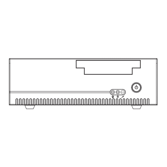
Page 14: System Overview
Chapter 2 Getting Started 2.2 System Overview Unit: mm 2.2.1 Front View 2.2.2 Rear View COM3 COM5 COM4 COM6 COM2 DVI-D COM1 DVI-D SA-5701 SERIES USER MANUAL Page: 2-3... -
Page 15: Top View
Chapter 2 Getting Started 2.2.3 Top View 300.2 2.2.4 Bottom View SA-5701 SERIES USER MANUAL Page: 2-4... -
Page 16: Side View
Chapter 2 Getting Started 2.2.5 Side View 2.2.6 Quarter View SA-5701 SERIES USER MANUAL Page: 2-5... -
Page 17: System Specifications
1 x parallel port (optional) Parallel Port 1 x PS/2 (only keyboard signals) PS/2 Environment Operating Temperature HDD: 0°C ~ 40°C (32°F~ 104°F) Storage Temperature -20°C ~ 80°C (-4°F~ 176°F) Humidity 20%~ 90% SA-5701 SERIES USER MANUAL Page: 2-6... -
Page 18: Safety Precautions
Avoid direct sunlight exposure for a long period of time (for example, in a closed car in summer time. Also avoid the system from any heating device.). Or do not use SA-5701 when it has been left outdoors in a cold winter day. •... -
Page 19: System Configuration
The following topics are included: • External I/O Ports Diagram • Main Board Jumper Settings and Component Locations • How to Set Jumpers • Setting Main Board Connectors and Jumpers SA-5701 SERIES USER MANUAL Page: 3-1... -
Page 20: External I/O Ports Diagram
Rear I/O Ports Diagram LAN1 LAN2 PS/2 Keyboard Connector COM4 COM6 COM3 COM5 COM5 COM3 COM6 COM4 COM2 DVI-D COM1 DVI-D COM2 Line In COM1 DVI-D USB 3.0 Line Out Mic In USB 2.0 SA-5701 SERIES USER MANUAL Page: 3-2... -
Page 21: Jumper & Connector Quick Reference Table
(Optional) Display Connector HD Audio Connector AUDIO1 (Optional) Printer Port (LPT) LPT1 Connector Front Panel Connector CPU Fan Connector CPU_FAN1 System Fan Connector SYS_FAN1 Half-Sized Mini PCI Express Slots M_PCIE1 PCI Express Slots (PCIe (x16)) PCI_E1 SA-5701 SERIES USER MANUAL Page: 3-2... - Page 22 Chapter 3 System Configuration CONNECTOR Description NAME SATA 3.0 Connectors SATA1, SATA2 ATX Power Input Connectors ATX_PWR1, ATX_PWR2 SPI Connector Low Pin Count (LPC) Connector JP12 DDR4 SO-DIMM memory socket SO-DIMM1 DDR4 SO-DIMM memory socket SO-DIMM2 SA-5701 SERIES USER MANUAL Page: 3-3...
-
Page 23: Component Locations
Make sure both the system and peripheral devices are turned OFF as sudden surge of power could damage sensitive components. Make sure SA-5701 is properly grounded. CAUTION: Observe precautions while handling electrostatic sensitive components. Make sure to ground yourself to prevent static charge while you are working on the connectors and jumpers. -
Page 24: Bottom View Of Bm-2505 Main Board
Take special cares while you are holding electronic circuit boards by the edges only. Do not touch the main board components. 3.3.2 Bottom View of BM-2505 Main Board Figure 3-2 BM-2505 Main Board Component Location (Bottom View) SA-5701 SERIES USER MANUAL Page: 3-5... -
Page 25: Setting Jumpers
2 to create one setting and shorting. You can also select to connect pins 2 and 3 to create another setting. The format of the jumper picture will be illustrated throughout this manual. The figure below shows different types of jumpers and jumper settings. SA-5701 SERIES USER MANUAL Page: 3-6... - Page 26 Chapter 3 System Configuration Jumper diagrams Jumper settings SA-5701 SERIES USER MANUAL Page: 3-7...
-
Page 27: Setting Main Board Connectors And Jumpers
Jumper Location: JP_COM1 & JP_COM2 & JP_COM4 Description: COM1, COM2 and COM4 Port Pin9 RI/+5V/+12V Selection JUMPER ILLUSTRATION JUMPER SELECTION SETTING JP_COM1 JP_COM2 JP_COM4 (Default Setting) JP_COM2 JP_COM4 JP_COM1 JP_COM2 JP_COM4 JP_COM1 JP_COM2 JP_COM4 JP_COM1 SA-5701 SERIES USER MANUAL Page: 3-8... -
Page 28: Com Ports
DTR# COM2 Note: COM2 Pin 9 is selectable for RI, +5V or +12V by jumper setting. Default setting is RI. Please see “COM1, COM2, COM4 Port Pin9 Definition Selection Guide” section for selection details. SA-5701 SERIES USER MANUAL Page: 3-9... - Page 29 COM4 Pin 9 is selectable for RI, +5V or +12V by jumper setting. Default setting is RI. Please see “COM1, COM2, COM4 Port Pin9 Definition Selection Guide” section for selection details. COM3(RS-232), COM4(RS-232) Connector Pin Header Pin Assignment: ASSIGNMENT ASSIGNMENT DCD# DSR# RTS# CTS# DTR# COM3/ COM4 Pin Header SA-5701 SERIES USER MANUAL Page: 3-10...
- Page 30 (Optional) COM5(RS-232), COM6 (RS-232) Connector Pin Assignment: ASSIGNMENT ASSIGNMENT DCD# DSR# RTS# CTS# COM5/ DTR# COM6 COM5(RS-232),COM6 (RS-232) Connector Pin Header Pin Assignment: ASSIGNMENT ASSIGNMENT DCD# DSR# RTS# CTS# DTR# COM5/ COM6 Pin Header SA-5701 SERIES USER MANUAL Page: 3-11...
-
Page 31: Com1 Rs-232/422/485 Selection
Chapter 3 System Configuration 3.5.3 COM1 RS-232/422/485 Selection Jumper Location: JP6 Description: COM1 RS-232/422/485 Selection SELECTION JUMPER SETTINGS JUMPER ILLUSTRATION Open RS-232 (Default Setting) 1-2, RS-422 3-4, 9-10 1-2, RS-485 5-6, SA-5701 SERIES USER MANUAL Page: 3-12... -
Page 32: Com1 Rs-485 Auto Flow Selection
Chapter 3 System Configuration 3.5.4 COM1 RS-485 Auto Flow Selection Jumper Location: JP11 Description: COM1 RS-485 Auto Flow Selection SELECTION JUMPER SETTINGS JUMPER ILLUSTRATION Disable JP11 Enable (Default Setting) JP11 SA-5701 SERIES USER MANUAL Page: 3-13... -
Page 33: Lan And Dual Usb 3.0 Ports
No LAN switch/hub connected Right Side LED Yellow Color Blinking LAN Message Active LAN1_USB1 No LAN Message Active USB 3.0 signals: ASSIGNMENT ASSIGNMENT VCC5 VCC5 USBP1N USBP2N USBP1P USBP2P RX1_DN RX2_DN RX1_DP RX2_DP TX1_DN TX2_DN TX1_DP TX2_DP SA-5701 SERIES USER MANUAL Page: 3-14... - Page 34 No LAN switch/hub connected Right Side LED Yellow Color Blinking LAN Message Active No LAN Message Active LAN2_USB2/ USB 3.0 signals: ASSIGNMENT ASSIGNMENT VCC5 VCC5 USBP3N USBP4N USBP3P USBP4P RX3_DN RX4_DN RX3_DP RX4_DP TX3_DN TX4_DN TX3_DP TX4_DP SA-5701 SERIES USER MANUAL Page: 3-15...
-
Page 35: Ps/2 Keyboard Connector And 2 X 1 Usb 2.0 Connectors
PS/2 Keyboard Connector and 2 x 1 USB 2.0 Connectors Port Name: JPS2_USB1 (rear I/O) Description: PS/2 Keyboard Connector and 2 x USB 2.0 Connectors JPS2_USB1 Keyboard signals: ASSIGNMENT ASSIGNMENT DATA USB 2.0 signals: ASSIGNMENT ASSIGNMENT VCC5 VCC5 USB_P6_DN USB_P5_DN USB_P6_DP USB_P5_DP SA-5701 SERIES USER MANUAL Page: 3-16... -
Page 36: Keyboard / Mouse Mode Selection
Chapter 3 System Configuration 3.5.7 Keyboard / Mouse Mode Selection Jumper Location: JP13 Description: Keyboard / Mouse Mode Selection SELECTION JUMPER SETTINGS JUMPER ILLUSTRATION Keyboard 1-3, 2-4 Mode (Default Setting) JP13 Mouse Mode 3-5, 4-6 JP13 SA-5701 SERIES USER MANUAL Page: 3-17... -
Page 37: Internal Usb 2.0 Connector
Chapter 3 System Configuration 3.5.8 Internal USB 2.0 Connector Connector Location: USB3 Description: Internal USB 2.0 Connector USB 2.0 connector signals: ASSIGNMENT ASSIGNMENT USB_5_VCC5 USB_5_VCC5 USB2_P9_DN_R USB2_P7_DN USB2_P9_DP_R USB2_P7_DP USB3 SA-5701 SERIES USER MANUAL Page: 3-18... -
Page 38: Dual Dvi-D Ports
Description: 2 x DVI (Digital Visual Interface) Integrated Connectors (Supports only DVI-D signals) DVI1 DVI1 connector signals (A): ASSIGNMENT ASSIGNMENT DP_Data2- DP_Data2+ +5V Power Ground Ground HOT Plug Detect DP_Data0- DP_Ctrl_Clock DP_Data0+ DP_Ctrl_ Data Ground CRT_VSYNC DP_Data1- DP_Data1+ Ground Ground DP_Clock+ DP_Clock- SA-5701 SERIES USER MANUAL Page: 3-19... - Page 39 Chapter 3 System Configuration DVI1 connector signals (B): ASSIGNMENT ASSIGNMENT DP_Data2- DP_Data2+ +5V Power Ground Ground HOT Plug Detect DP_Data0- DP_Ctrl_Clock DP_Data0+ DP_Ctrl_ Data Ground CRT_VSYNC DP_Data1- DP_Data1+ Ground Ground DP_Clock+ DP_Clock- SA-5701 SERIES USER MANUAL Page: 3-20...
-
Page 40: Displayport Connector (Optional)
Chapter 3 System Configuration 3.5.10 DisplayPort Connector (Optional) Connector Location: DP1 Description: DisplayPort Connector DP1 (optional) ASSIGNMENT ASSIGNMENT DP_C_DATA0+ DP_C_DATA0- DP_C_DATA1+ DP_C_DATA1- DP_C_DATA2+ DP_C_DATA2- DP_C_DATA3+ DP_C_DATA3- DP_C_AUX_ENJ DP_C_AUX+ DP_C_HPD DP_C_AUX- DP_VCC3_3 DP_VCC5 DP_VCC3_3 SA-5701 SERIES USER MANUAL Page: 3-21... -
Page 41: Hd Audio Connector
Chapter 3 System Configuration 3.5.11 HD Audio Connector Connector Location: AUDIO1 Description: HD Audio Connector for Line In/Line Out/Mic In. Line In: ASSIGNMENT HD_LINE-IN-L HD_LINE-IN-R Line Out: ASSIGNMENT LINE-OUT-L LINE-OUT-R Mic In: AUDIO1 ASSIGNMENT HD_MIC1-L_L HD_MIC1-R_L SA-5701 SERIES USER MANUAL Page: 3-22... -
Page 42: Printer Port Connector (Optional)
Chapter 3 System Configuration 3.5.12 Printer Port Connector (Optional) Connector Location: LPT1 Description: Printer Port Connector LPT1 (optional) Printer Port (LPT1) signals: ASSIGNMENT ASSIGNMENT STRB# ERR# INIT SLIN ACK# BUSY SLCT SA-5701 SERIES USER MANUAL Page: 3-23... -
Page 43: Front Panel Connector
Chapter 3 System Configuration 3.5.13 Front Panel Connector Connector Location: FP1 Description: Front Panel Connector ASSIGNMENT ASSIGNMENT HDD+ PWR+ HDD- PWR- Power Button Reset Button SA-5701 SERIES USER MANUAL Page: 3-24... -
Page 44: Cpu Fan Connector
2. Default BIOS setting is “Auto Duty-Cycle Mode”. Please see Chapter 5 for more details. 3.5.15 System Fan Connector Connector Location: SYS_FAN1 Description: System Fan Connector System Fan Connector (SYS_FAN1) signals: ASSIGNMENT VCC12 SYS_FAN1 SA-5701 SERIES USER MANUAL Page: 3-25... -
Page 45: Half-Sized Mini Pci Express Slots
Mini PCI Express is the successor of the Mini PCI card and provides an increased data throughput. The cards have a detached network interface and are equipped with one lane. They are used in particular in embedded designs or compact box PCs. SA-5701 SERIES USER MANUAL Page: 3-26... -
Page 46: Pci Express Slots
PRSNT#2 HSIN3 HSOP4 RSVD RSVD HSON4 HSIP4 HSOP5 HSIN4 HSON5 HSIP5 HSOP6 HSIN5 HSON6 HSIP6 HSOP7 HSIN6 HSON7 HSIP7 PRSNT#2 HSIN7 HSOP8 HSON8 RSVD HSIP8 HSIN8 HSOP9 HSON9 HSIP9 HSIN9 HSOP10 HSON10 HSIP10 HSIN10 SA-5701 SERIES USER MANUAL Page: 3-27... - Page 47 Chapter 3 System Configuration ASSIGNMENT ASSIGNMENT ASSIGNMENT ASSIGNMENT HSOP11 HSON11 HSIP11 HSIN11 HSOP12 HSON12 HSIP12 HSIN12 HSOP13 HSON13 HSIP13 HSIN13 HSOP14 HSIN14 HSIP14 HSIN14 HSIP15 HSIN15 PRSNT#2 HSIP15 HSIN15 RSVD SA-5701 SERIES USER MANUAL Page: 3-28...
-
Page 48: Sata 3.0 Connectors
Description: Serial ATA (SATA) 6GB/s Connector SATA1 Serial ATA 6GB/s Connector (SATA1) signals: ASSIGNMENT TXPC TXNC RXNC RXPC Connector Location: SATA2 Description: Serial ATA (SATA) 6GB/s Connector SATA2 Serial ATA 6GB/s Connector (SATA2) signals: ASSIGNMENT TXPC TXNC RXNC RXPC SA-5701 SERIES USER MANUAL Page: 3-29... -
Page 49: Atx Power Connectors
ATX_PWR1 ATX Power Connector signals: ASSIGNMENT ASSIGNMENT +3.3V +3.3V +3.3V PSON PWROK 5VSB +12V +12V +3.3V ATX_PWR1 Connector Location: ATX_PWR2 Description: DC Power Input Connector ATX_PWR2 DC Power Input Connector signals: ASSIGNMENT ASSIGNMENT +12V +12V ATX_PWR2 SA-5701 SERIES USER MANUAL Page: 3-30... -
Page 50: At / Atx Mode Selection
Jumper Location: JP2 Description: AT / ATX Mode Selection SELECTION JUMPTER SETTING JUMPER ILLUSTRATION (Default Setting) Jumper Location: JP3 Description: AT / ATX Mode Selection SELECTION JUMPTER SETTING JUMPER ILLUSTRATION Close Open (Default Setting) SA-5701 SERIES USER MANUAL Page: 3-31... -
Page 51: Spi Connector
Description: SPI (Serial Peripheral Interface Bus) Connector ASSIGNMENT ASSIGNMENT 3.3V MISO MOSI 3.5.22 SPI Override Protection Selection Jumper Location: JP9 Description: SPI Override Protection Selection SELECTION JUMPER SETTING JUMPER ILLUSTRATION Open Enable (Default Setting) Disable Close SA-5701 SERIES USER MANUAL Page: 3-32... -
Page 52: Intruder Detection Selection
Chapter 3 System Configuration 3.5.23 Intruder Detection Selection Jumper Location: JP4 Description: Intruder Detection Selection SELECTION JUMPER SETTING JUMPER ILLUSTRATION Enable Close Open Disable (Default Setting) SA-5701 SERIES USER MANUAL Page: 3-33... -
Page 53: Low Pin Count (Lpc) Connector
LPC_AD0 LPC_AD3 LPC_AD2 3.3V LPC_AD1 JP12 3.5.25 Clear RTC Data Selection Jumper Location: JRTC1 Description: Clear RTC Data Selection SELECTION JUMPER SETTINGS JUMPER ILLUSTRATION Open Normal (Default Setting) JRTC1 Clear RTC Close Data JRTC1 SA-5701 SERIES USER MANUAL Page: 3-34... -
Page 54: Vccio Voltage Selection
Chapter 3 System Configuration 3.5.26 VCCIO Voltage Selection Jumper Location: JP1 Description: VCCIO Voltage Selection SELECTION JUMPER SETTING JUMPER ILLUSTRATION 0.95V (Default Setting) 1.0V SA-5701 SERIES USER MANUAL Page: 3-35... -
Page 55: Bios Recovery Mode Selection
Chapter 3 System Configuration 3.5.27 BIOS Recovery Mode Selection Jumper Location: JP5 Description: BIOS Recovery Mode Selection SELECTION JUMPER SETTING JUMPER ILLUSTRATION Normal (Default Setting) Configure Recovery Open SA-5701 SERIES USER MANUAL Page: 3-36... -
Page 56: Clear Cmos Data Selection
Step 4. Power on the PC and the PC will then auto-reboot for once in order to set SoC’s register. Step 5. Done! SELECTION JUMPER SETTINGS JUMPER ILLUSTRATION Open Normal (Default Setting) JCMOS1 Clear CMOS Close Data JCMOS1 Note: Please make sure the main power is off before you clear CMOS. SA-5701 SERIES USER MANUAL Page: 3-37... -
Page 57: Software Utilities
• Installing Intel ® Chipset Software Installation Utility • Installing Intel ® Management Engine Components Installer • Installing USB 3.0 eXtensible Host Controller Utility • Installing Graphics Driver Utility • Installing LAN Driver Utility • Installing Sound Driver Utility SA-5701 SERIES USER MANUAL Page: 4-1... -
Page 58: Introduction
Chapter 4 Software Utilities 4.1 Introduction Enclosed with the SA-5701 Series package is our driver utilities contained in a DVD-ROM disk. Refer to the following table for driver locations: Filename (Assume that Purpose DVD- ROM drive is D :) Shell Win7 Win8.1 Win10 ... - Page 59 Audio System Software Intel(R) Management D:\Driver\Platform\ME\ Engine Components Win10(64-bit) installer D:\Driver\Platform\KMDF\ Kernel-Mode Driver Win7(32-bit) Framework X : Not support : Support Note: Install the driver utilities immediately after the OS installation is completed. SA-5701 SERIES USER MANUAL Page: 4-3...
-
Page 60: Installing Intel ® Chipset Software Installation Utility
OS installation is finished. Please follow the steps below: Connect the USB DVD-ROM device to SA-5701 and insert the driver disk. Enter the Main Chip folder where the Chipset driver is located. -
Page 61: Intel Management Engine Components Installer Installation
® Installation Instructions for Intel Management Engine Components Installer Connect the USB DVD-ROM device to SA-5701 and insert the driver disk. Enter the ME Installation Driver folder where the driver is located. Select Windows 7 (32/64-bit) / Windows 8.1 (64-bit) / Windows 10 (64-bit) for your OS platform. -
Page 62: Intel ® Usb 3.0 Extensible Host Controller Utility
Chapter 4 Software Utilities Once the installation is completed, shut down the system and restart SA-5701 for the changes to take effect. ® 4.4 Intel USB 3.0 eXtensible Host Controller Utility ® Intel USB 3.0 eXtensible Host Controller Driver supports the ®... -
Page 63: Installing Graphics Driver Utility
Chapter 4 Software Utilities 4.6 Installing Graphics Driver Utility The graphics interface embedded in SA-5701 can support a wide range of display types. You can have dual displays via DVI-D ports and make the system work simultaneously. To install the Graphics driver utility, follow the steps below: Connect the USB DVD-ROM device to SA-5701 and insert the driver disk. -
Page 64: Installing Lan Driver Utility
4.7 Installing LAN Driver Utility Enhanced with LAN function, SA-5701 supports various network adapters. To install the LAN Driver, follow the steps below: Connect the USB DVD-ROM device to SA-5701 and insert the driver disk. Enter the LAN folder where the driver is located. -
Page 65: Installing Sound Driver Utility
Windows 7/8.1/10 series. To install the Sound Driver, follow the steps below: Connect the USB DVD-ROM device to SA-5701 and insert the driver disk. Open the Sound folder where the driver is located. Select Windows 7 (32/64-bit) / Windows 8.1 (64-bit) / Windows 10 (64-bit) for your OS platform. -
Page 66: Bios Setup
The BIOS Setup Utilities consist of the following menu items: Accessing Setup Utilities • Main Menu • Advanced Menu • Chipset Menu • Security Menu • Boot Menu • Save & Exit Menu • SA-5701 SERIES USER MANUAL Page: 5-1... -
Page 67: Introduction
Chapter 5 BIOS Setup 5.1 Introduction The SA-5701 System uses an AMI (American Megatrends Incorporated) Aptio BIOS that is stored in the Serial Peripheral Interface Flash Memory (SPI Flash) and can be updated. The SPI Flash contains the built-in BIOS setup program, Power-On Self-Test (POST), PCI auto-configuration utility, LAN EEPROM information, and Plug and Play support. - Page 68 BIOS setup menu by pressing <Del> or <Esc> immediately while the POST message is running before the operating system is loading. All the menu settings are described in details in this chapter. SA-5701 SERIES USER MANUAL Page: 5-3...
-
Page 69: Accessing Setup Utility
Self-Test (POST) routines and the POST message will be displayed: Figure 5-2. POST Screen with AMI Logo Press <Del> or <Esc> to access the Setup Utility program and the Main menu of the Aptio Setup Utility will appear on the screen as shown: SA-5701 SERIES USER MANUAL Page: 5-4... - Page 70 Select a different menu screen (move the cursor from the selected menu to the left or right). <↑> and <↓> Select a different item (move the cursor from the selected item upwards or downwards) SA-5701 SERIES USER MANUAL Page: 5-5...
- Page 71 Load the previous configuration values. <F3> Load the default configuration values. <F4> Save the current values and exit the BIOS setup menu. <Esc> Close the sub-menu. Trigger the confirmation to exit BIOS setup menu. SA-5701 SERIES USER MANUAL Page: 5-6...
-
Page 72: Main
Month, day, year Sets the system date. The format is [Day Month/ Date/ Year]. Users can directly enter values or use <+> or <-> arrow keys to increase/decrease it. The “Day” is automatically changed. SA-5701 SERIES USER MANUAL Page: 5-7... - Page 73 BIOS Setting Options Description/Purpose System Time Hour, minute, second Sets the system time. The format is [Hour: Minute: Second]. Users can directly enter values or use <+> or <-> arrow keys to increase/decrease it. SA-5701 SERIES USER MANUAL Page: 5-8...
-
Page 74: Advanced
F81866 Super IO Sub-Menu System Super I/O Chip Parameters. Configuration Hardware Monitor Sub-Menu Monitor hardware status. F81866 Watchdog Sub-Menu F81866 Watchdog Parameters. Network Stack Sub-Menu Network Stack Settings. Configuration USB Configuration Sub-Menu USB Configuration Parameters. SA-5701 SERIES USER MANUAL Page: 5-9... -
Page 75: Advanced - Cpu Configuration
No changeable options Displays L4 Cache size. No changeable options Supports Intel VMX Technology. SMX/TXT No changeable options Reports if Intel Secure Mode Extensions Technology (SMX) /Trusted Execution Technology (TXT) is supported by the processor. SA-5701 SERIES USER MANUAL Page: 5-10... - Page 76 Enabling this function will improve parallelization of computation performed on PC microprocessor. For each processor core that is physically present, the operating system addresses two virtual processors, and shares the workload between them when possible. SA-5701 SERIES USER MANUAL Page: 5-11...
-
Page 77: Advanced - Sata Configuration
Port 1 - 2 - Disabled Enables or Disables SATA Port Device. - Enabled Hot Plug - Disabled Enables or Disables SATA Port Device - Enabled Hot Plug function to designate a SATA port device as hot-pluggable. SA-5701 SERIES USER MANUAL Page: 5-12... -
Page 78: Advanced - Pch-Fw Configuration
Description/Purpose ME Firmware Version No changeable options Displays the ME Firmware Version. ME Firmware Mode No changeable options Displays the ME Firmware Mode. ME Firmware SKU No changeable options Displays the ME Firmware SKU. SA-5701 SERIES USER MANUAL Page: 5-13... -
Page 79: Advanced - Acpi Settings
SUSPEND button is pressed. Lock Legacy - Disabled Enables or Disables Lock of Legacy Resources - Enabled Resources. - Disabled Enables or Disables S3 Video Repost. S3 Video Repost - Enabled SA-5701 SERIES USER MANUAL Page: 5-14... -
Page 80: Advanced - F81866 Super Io Configuration
Serial Port 5 Configuration Sub-Menu Sets the parameters of Serial Port 5 (COME). Serial Port 6 Configuration Sub-Menu Sets the parameters of Serial Port 6 (COMF). Parallel Port Sub-Menu Sets the parameters of Parallel Port (LPT). SA-5701 SERIES USER MANUAL Page: 5-15... - Page 81 Serial Port 1. Change Settings - Auto Allows you to select specific - IO=3F8h; IRQ=4 I/O address and IRQ for - IO=3F8h; IRQ=3,4,5,6,7,10,11 Serial Port 1. - IO=2F8h; IRQ=3,4,5,6,7,10,11 - IO=3E8h; IRQ=3,4,5,6,7,10,11 - IO=2E8h; IRQ=3,4,5,6,7,10,11 SA-5701 SERIES USER MANUAL Page: 5-16...
- Page 82 Serial Port 2. Change Settings - Auto Allows you to select specific - IO=2F8h; IRQ=3 I/O address and IRQ for - IO=3F8h; IRQ=3,4,5,6,7,10,11 Serial Port 2. - IO=2F8h; IRQ=3,4,5,6,7,10,11 - IO=3E8h; IRQ=3,4,5,6,7,10,11 - IO=2E8h; IRQ=3,4,5,6,7,10,11 SA-5701 SERIES USER MANUAL Page: 5-17...
- Page 83 Serial Port 3. Change Settings - Auto Allows you to select specific - IO=3E8h; IRQ=7 I/O address and IRQ for - IO=3E8h; IRQ=3,4,5,6,7,10,11 Serial Port 3. - IO=2E8h; IRQ=3,4,5,6,7,10,11 - IO=2F0h; IRQ=3,4,5,6,7,10,11 - IO=2E0h; IRQ=3,4,5,6,7,10,11 SA-5701 SERIES USER MANUAL Page: 5-18...
- Page 84 Serial Port 4. Change Settings - Auto Allows you to select specific - IO=2E8h; IRQ=10 I/O address and IRQ for - IO=3E8h; IRQ=3,4,5,6,7,10,11 Serial Port 4. - IO=2E8h; IRQ=3,4,5,6,7,10,11 - IO=2F0h; IRQ=3,4,5,6,7,10,11 - IO=2E0h; IRQ=3,4,5,6,7,10,11 SA-5701 SERIES USER MANUAL Page: 5-19...
- Page 85 Serial Port 5. Change Settings - Auto Allows you to select specific - IO=2F0h; IRQ=6 I/O address and IRQ for - IO=3E8h; IRQ=3,4,5,6,7,10,11 Serial Port 5. - IO=2E8h; IRQ=3,4,5,6,7,10,11 - IO=2F0h; IRQ=3,4,5,6,7,10,11 - IO=2E0h; IRQ=3,4,5,6,7,10,11 SA-5701 SERIES USER MANUAL Page: 5-20...
- Page 86 Serial Port 6. Change Settings - Auto Allows you to select specific - IO=2E0h; IRQ=11 I/O address and IRQ for - IO=3E8h; IRQ=3,4,5,6,7,10,11 Serial Port 6. - IO=2E8h; IRQ=3,4,5,6,7,10,11 - IO=2F0h; IRQ=3,4,5,6,7,10,11 - IO=2E0h; IRQ=3,4,5,6,7,10,11 SA-5701 SERIES USER MANUAL Page: 5-21...
- Page 87 DMA resource. - EPP-1.7 and SPP Mode After Mode is changed, reset - ECP Mode the system to reflect actual - ECP and EPP 1.9 Mode device settings. - ECP and EPP 1.7 Mode SA-5701 SERIES USER MANUAL Page: 5-22...
-
Page 88: Advanced - Hardware Monitor
No changeable options the VCC5V in supply. Detects and displays voltage level of VCC12 No changeable options the VCC12 in supply. Detects and displays voltage level of VCC3V No changeable options the VCC3V in supply. SA-5701 SERIES USER MANUAL Page: 5-23... -
Page 89: Advanced - Hardware Monitor - Smart Fan Mode
Smart Fan Mode selection for CPU Control - Auto Duty-Cycle Mode Fan. Manual Duty Mode Numeric (from 1 to 100) Manual mode fan control. Users can write expected duty cycle from 1-100 (PWM fan type). SA-5701 SERIES USER MANUAL Page: 5-24... -
Page 90: Advanced - F81866 Watchdog Configuration
Selects 1s (second) or 60s (minute) as Watchdog timer unit - 60s the time unit of Watchdog timer. Count for Timer Numeric Sets the timeout for Watchdog timer. (Seconds) (from 1 to 255) (Max. value: 255 seconds or minutes) SA-5701 SERIES USER MANUAL Page: 5-25... -
Page 91: Advanced - Network Stack Configuration
IPv6 PXE boot option will not be created. PXE boot wait Number of seconds to wait for PXE boot Numeric (from 0 to 5) time to abort after the Esc key is pressed. SA-5701 SERIES USER MANUAL Page: 5-26... -
Page 92: Advanced - Usb Configuration
The USB Configuration allows users to enable/disable USB mass storage driver support. USB Configuration Screen BIOS Setting Options Description/Purpose USB Mass Storage - Enabled Enables or Disables USB mass storage Driver Support - Disabled driver support. SA-5701 SERIES USER MANUAL Page: 5-27... -
Page 93: Chipset
This menu allows users to configure advanced Chipset settings such as System Agent (SA) and PCH-IO configuration parameters. Chipset Screen BIOS Setting Options Description/Purpose System Agent (SA) Sub-Menu System Agent (SA) parameters. Configuration PCH-IO Configuration Sub-Menu PCH parameters. SA-5701 SERIES USER MANUAL Page: 5-28... -
Page 94: Chipset - System Agent (Sa) Configuration
I/O devices in virtualized environment. Memory Sub-Menu Displays the DRAM information on the Configuration platform. SA-5701 SERIES USER MANUAL Page: 5-29... -
Page 95: Chipset - Sa Configuration - Memory Configuration
No changeable options Displays the Frequency of Memory. Memory Timings No changeable options Displays the Memory (RAM) timings (tCL-tRCD-tRP-tRAS) and latency. • CAS Latency (tCL) - This is the most important memory timing. CAS stands SA-5701 SERIES USER MANUAL Page: 5-30... - Page 96 (tRAS = tCL + tRCD + tRP). Displays if SO-DIMM#1 socket is SO-DIMM#1 No changeable options populated/enabled or not. Displays if SO-DIMM#2 socket is SO-DIMM#2 No changeable options populated/enabled or not. Size No changeable options Displays the total memory size. SA-5701 SERIES USER MANUAL Page: 5-31...
-
Page 97: Chipset - System Agent (Sa) Configuration - Graphics
Selects which of IGFX/PEG Graphics Primary Display - IGFX device should be Primary Display. - PEG - Auto Keeps IGFX enabled based on the setup Internal Graphics - Disabled options. - Enabled LCD Control Sub-Menu LCD Control sub-menu. SA-5701 SERIES USER MANUAL Page: 5-32... - Page 98 - VBIOS default Selects Primary Display Device. Boot Display - DVI-D 1 - DVI-D 2 - DisplayPort Secondary IGFX - Disabled Selects Secondary Display Device. Boot Display - DVI-D 1 - DVI-D 2 - DisplayPort SA-5701 SERIES USER MANUAL Page: 5-33...
-
Page 99: Chipset -System Agent (Sa) Configuration - Peg Port
Enables or Disables the Root Port. - Enabled - Auto Max Link Speed - Auto Configures PCI-E1 maximum speed. - Gen1 - Gen2 - Gen3 Detect - Disabled Detects Non-Compliance PCI Express Non-Compliance - Enabled Device in PEG. Device SA-5701 SERIES USER MANUAL Page: 5-34... -
Page 100: Chipset - Pch-Io Configuration
Default: Enabled. State After G3 - Power On Specifies the Power On/Off state that the - Power Off system will go into when the power is re-applied following a power failure (G3 state). SA-5701 SERIES USER MANUAL Page: 5-35... -
Page 101: Chipset - Pch-Io Configuration - Pci Express
PCI Express Configuration Screen BIOS Setting Options Description/Purpose PCIE Port No changeable options Displays the LAN assigned PCIE Port. assigned to LAN Mini PCI Express Configures Mini PCI Express Port Sub-Menu Port settings. SA-5701 SERIES USER MANUAL Page: 5-36... -
Page 102: Configuration
- L1.2 - L1.1 & L1.2 Hot Plug - Disabled Enables or Disables PCI Express Hot - Enabled Plug. PCIe Speed - Auto Selects PCI Express Port Speed. - Gen1 - Gen2 - Gen3 SA-5701 SERIES USER MANUAL Page: 5-37... -
Page 103: Security
An administrator has much more privileges over the settings in the Setup utility than a user. Heed that a user password does not provide access to most of the features in the Setup utility. Security Screen SA-5701 SERIES USER MANUAL Page: 5-38... - Page 104 <Enter>, and the password dialog entry box appears. Select the configured Administrator Password or User Password that you want to delete. Leave the dialog box blank and press <Enter>. Press <Enter> again when the password confirmation box appears. SA-5701 SERIES USER MANUAL Page: 5-39...
-
Page 105: Boot
Selects the NumLock sate after the system NumLock State - Off is powered on. • On: Enables the NumLock function automatically after the system is powered on. • Off: Disables the NumLock function after the system is powered on. SA-5701 SERIES USER MANUAL Page: 5-40... - Page 106 Note that in the menu displayed, you will only see the device with the highest priority for a specific boot device type. Sub-Menu CSM configuration: Enable/Disable, Configuration Option ROM execution settings, etc. SA-5701 SERIES USER MANUAL Page: 5-41...
-
Page 107: Boot - Csm Configuration
Boot option filter - UEFI and Legacy This option controls Legacy/UEFI ROMs - UEFI only priority. Network - Do not launch Controls the execution of UEFI and Legacy PXE OpROM. - UEFI - Legacy SA-5701 SERIES USER MANUAL Page: 5-42... - Page 108 - Do not launch - UEFI Legacy Video OpROM. - Legacy Other PCI Determines OpROM execution policy for - Do not launch devices devices other than Network, Storage or - UEFI - Legacy Video. SA-5701 SERIES USER MANUAL Page: 5-43...
-
Page 109: Save & Exit
Discard Changes and Reset to discard any changes you have made and restore the factory BIOS defaults. Load User Defaults You may simply press F3 at any time to load the Optimized Values which resets all BIOS settings to the factory defaults. Save & Exit Screen SA-5701 SERIES USER MANUAL Page: 5-44... - Page 110 Saves the changes done so far as User No changeable options Defaults Defaults. Restore User Restores the User Defaults to all the BIOS No changeable options Defaults settings. Boot Override - [Drive(s)] Forces to boot from selected [drive(s)]. SA-5701 SERIES USER MANUAL Page: 5-45...
-
Page 111: Appendix A System Diagrams
This appendix includes the exploded diagrams of the system and the parts list as well as the part numbers of the SA-5701 system. • SA-5701 System Exploded Diagram • SA-5701 CPU Heat Sink Exploded Diagram • SA-5701 SATA HDD Exploded Diagram SA-5701 SERIES USER MANUAL Page: A-1... - Page 112 Appendix A System Diagrams SA-5701 System Exploded Diagram 6 8X 18 8X 4X 7 SA-5701 SERIES USER MANUAL Page: A-2...
- Page 113 Appendix A System Diagrams Component Name Part No. Q’ty SA-5701 INNER CHASSIS ASM 80-015-03001445 BM-2505_MAIN_PCB_ASSY_EXP See Page A-4 DRIVER_BAY_KIT_ASM See Page A-5 ST-1808 FRONT PANEL STD TYPE C(Black) 30-003-28210006 ST-1082/SA-5082 COM PORT CABLE(9M to 27-024-23702031 10F)L=95mm HEX CU BOSS UNC No.4-40,L=4.8,H=7mm 22-692-40048051 FLAT HEAD SCREW M3x0.5Px6mm(Black)
-
Page 114: Sa-5701 Cpu Heat Sink Exploded Diagram
Appendix A System Diagrams SA-5701 CPU Heat Sink Exploded Diagram Component Name Part No. Q’ty BM_2505 MAINBOARD CPU HEAT SINK(ψ90x13) & FAN 21-003-09595001 (95x95x16.8mm) L=300mm SA-5701 SERIES USER MANUAL Page: A-4... -
Page 115: Sa-5701 Sata Hdd Exploded Diagram
Appendix A System Diagrams SA-5701 SATA HDD Exploded Diagram Component Name Part No. Q’ty PMB-531LF DRIVE BAY FOR 2.5” HDD 20-004-03001082 2.5”_HDD_SATA FILLISTER HEAD SCREW #2 / M3x0.5Px5mm 22-272-30049015 SA-5701 SERIES USER MANUAL Page: A-5... -
Page 116: Appendix B Technical Summary
The following topics are included: • System Block Diagram • Interrupt Map • I/O Map • DMA Channels Map • Memory Map • Configuring WatchDog Timer • Flash BIOS Update SA-5701 SERIES USER MANUAL Page: B-1... -
Page 117: System Block Diagram
High Definition Codec SPI Flash ROM LOW PIN COUNT 80 PORT for Debug COM1 RS 232/422/485 Connector COM2/3/4/5/6 RS232 FINTEK CPU FAN*1, SYSTEM FAN*1 LPC SIO COM1/2/4 support 5V/12V HW monitor F81866AD-I LPT Port [Wafer 25pins] SA-5701 SERIES USER MANUAL Page: B-2... -
Page 118: Interrupt Map
IRQ 72 Microsoft ACPI-Compliant System IRQ 73 Microsoft ACPI-Compliant System IRQ 74 Microsoft ACPI-Compliant System IRQ 75 Microsoft ACPI-Compliant System IRQ 76 Microsoft ACPI-Compliant System IRQ 77 Microsoft ACPI-Compliant System IRQ 78 Microsoft ACPI-Compliant System SA-5701 SERIES USER MANUAL Page: B-3... - Page 119 IRQ 111 Microsoft ACPI-Compliant System IRQ 112 Microsoft ACPI-Compliant System IRQ 113 Microsoft ACPI-Compliant System IRQ 114 Microsoft ACPI-Compliant System IRQ 115 Microsoft ACPI-Compliant System IRQ 116 Microsoft ACPI-Compliant System IRQ 117 Microsoft ACPI-Compliant System SA-5701 SERIES USER MANUAL Page: B-4...
- Page 120 IRQ 150 Microsoft ACPI-Compliant System IRQ 151 Microsoft ACPI-Compliant System IRQ 152 Microsoft ACPI-Compliant System IRQ 153 Microsoft ACPI-Compliant System IRQ 154 Microsoft ACPI-Compliant System IRQ 155 Microsoft ACPI-Compliant System IRQ 156 Microsoft ACPI-Compliant System SA-5701 SERIES USER MANUAL Page: B-5...
- Page 121 IRQ 189 Microsoft ACPI-Compliant System IRQ 190 Microsoft ACPI-Compliant System IRQ 191 Microsoft ACPI-Compliant System IRQ 192 Microsoft ACPI-Compliant System IRQ 193 Microsoft ACPI-Compliant System IRQ 194 Microsoft ACPI-Compliant System IRQ 195 Microsoft ACPI-Compliant System SA-5701 SERIES USER MANUAL Page: B-6...
- Page 122 IRQ 279 Microsoft ACPI-Compliant System IRQ 280 Microsoft ACPI-Compliant System IRQ 281 Microsoft ACPI-Compliant System IRQ 282 Microsoft ACPI-Compliant System IRQ 283 Microsoft ACPI-Compliant System IRQ 284 Microsoft ACPI-Compliant System IRQ 285 Microsoft ACPI-Compliant System SA-5701 SERIES USER MANUAL Page: B-7...
- Page 123 IRQ 318 Microsoft ACPI-Compliant System IRQ 319 Microsoft ACPI-Compliant System IRQ 320 Microsoft ACPI-Compliant System IRQ 321 Microsoft ACPI-Compliant System IRQ 322 Microsoft ACPI-Compliant System IRQ 323 Microsoft ACPI-Compliant System IRQ 324 Microsoft ACPI-Compliant System SA-5701 SERIES USER MANUAL Page: B-8...
- Page 124 IRQ 357 Microsoft ACPI-Compliant System IRQ 358 Microsoft ACPI-Compliant System IRQ 359 Microsoft ACPI-Compliant System IRQ 360 Microsoft ACPI-Compliant System IRQ 361 Microsoft ACPI-Compliant System IRQ 362 Microsoft ACPI-Compliant System IRQ 363 Microsoft ACPI-Compliant System SA-5701 SERIES USER MANUAL Page: B-9...
- Page 125 IRQ 396 Microsoft ACPI-Compliant System IRQ 397 Microsoft ACPI-Compliant System IRQ 398 Microsoft ACPI-Compliant System IRQ 399 Microsoft ACPI-Compliant System IRQ 400 Microsoft ACPI-Compliant System IRQ 401 Microsoft ACPI-Compliant System IRQ 402 Microsoft ACPI-Compliant System SA-5701 SERIES USER MANUAL Page: B-10...
- Page 126 IRQ 435 Microsoft ACPI-Compliant System IRQ 436 Microsoft ACPI-Compliant System IRQ 437 Microsoft ACPI-Compliant System IRQ 438 Microsoft ACPI-Compliant System IRQ 439 Microsoft ACPI-Compliant System IRQ 440 Microsoft ACPI-Compliant System IRQ 441 Microsoft ACPI-Compliant System SA-5701 SERIES USER MANUAL Page: B-11...
- Page 127 IRQ 474 Microsoft ACPI-Compliant System IRQ 475 Microsoft ACPI-Compliant System IRQ 476 Microsoft ACPI-Compliant System IRQ 477 Microsoft ACPI-Compliant System IRQ 478 Microsoft ACPI-Compliant System IRQ 479 Microsoft ACPI-Compliant System IRQ 480 Microsoft ACPI-Compliant System SA-5701 SERIES USER MANUAL Page: B-12...
- Page 128 Intel(R) I210 Gigabit Network Connection IRQ 4294967287 Intel(R) I210 Gigabit Network Connection IRQ 4294967288 Intel(R) I210 Gigabit Network Connection IRQ 4294967289 Intel(R) I210 Gigabit Network Connection IRQ 4294967290 Intel(R) USB 3.0 eXtensible Host Controller - 1.0 SA-5701 SERIES USER MANUAL Page: B-13...
- Page 129 IRQ 4294967291 Intel(R) HD Graphics 630 IRQ 4294967292 Intel(R) Ethernet Connection (2) I219-V IRQ 4294967293 Standard SATA AHCI Controller IRQ 4294967294 Intel(R) 100 Series/C230 Series Chipset Family PCI Express Root Port #6 - A115 SA-5701 SERIES USER MANUAL Page: B-14...
-
Page 130: I/O Map
Motherboard resources 0x000000B4-0x000000B5 Programmable interrupt controller 0x000000B8-0x000000B9 Programmable interrupt controller 0x000000BC-0x000000BD Programmable interrupt controller 0x000000F0-0x000000F0 Numeric data processor 0x000002E0-0x000002E7 Communications Port (COM6) 0x000002E8-0x000002EF Communications Port (COM4) 0x000002F0-0x000002F7 Communications Port (COM5) 0x000002F8-0x000002FF Communications Port (COM2) SA-5701 SERIES USER MANUAL Page: B-15... -
Page 131: Dma Channels Map
0x0000F080-0x0000F083 Standard SATA AHCI Controller 0x0000F090-0x0000F097 Standard SATA AHCI Controller 0x0000FF00-0x0000FFFE Motherboard resources 0x0000FFFF-0x0000FFFF Motherboard resources 0x0000FFFF-0x0000FFFF Motherboard resources 0x0000FFFF-0x0000FFFF Motherboard resources DMA Channels Map DMA Channels Map Assignment Channel 3 Printer Port (LPT1) SA-5701 SERIES USER MANUAL Page: B-16... -
Page 132: Memory Map
Motherboard resources 0xFE000000-0xFE01FFFF Motherboard resources 0xFE036000-0xFE03BFFF Motherboard resources 0xFE03D000-0xFE3FFFFF Motherboard resources 0xFE410000-0xFE7FFFFF Motherboard resources 0xDF144000-0xDF147FFF Intel(R) 100 Series/C230 Series Chipset Family PMC - A121 0x90000000-0xDFFFFFFF PCI Express Root Complex 0xFE40F000-0xFE40FFFF Intel(R) Management Engine Interface SA-5701 SERIES USER MANUAL Page: B-17... - Page 133 Intel(R) Ethernet Connection (2) I219-V 0xDF14E000-0xDF14EFFF Intel(R) 100 Series/C230 Series Chipset Family Thermal subsystem - A131 0xDF140000-0xDF143FFF High Definition Audio Controller 0xDF120000-0xDF12FFFF High Definition Audio Controller 0xA0000-0xBFFFF Intel(R) HD Graphics 630 0xA0000-0xBFFFF PCI Express Root Complex SA-5701 SERIES USER MANUAL Page: B-18...
-
Page 134: Configuring Watchdog Timer
To exit the Extended Function Mode, writing 0xAA to the EFER is required. Once the chip exits the Extended Function Mode, it is in the normal running mode and is ready to enter the configuration mode. SA-5701 SERIES USER MANUAL Page: B-19... - Page 135 ; -------------------------- Set timeout interval as 30 seconds ---------------------------- 0F6h ;------------------------------- Enable Watch PME-------------------------------------------- 0FAh ;------------------- Set second as counting unit and start counting -------------------- 0F5h 0F7h ;---------------------------- Exit the extended function mode ------------------------------ 0AAh SA-5701 SERIES USER MANUAL Page: B-20...
-
Page 136: Flash Bios Update
(3) The system will go into the BIOS setup menu. (4) Select [Boot] menu and enter into [CSM Configuration] menu. (5) Set [Boot option filter] to [UEFI Only] and press <F4> to save the configuration and restart the system. SA-5701 SERIES USER MANUAL Page: B-21... - Page 137 (6) Press <ESC> or <DEL> to enter BIOS setup menu again. (7) Select [Boot] menu and set [UEFI: Built-in EFI Shell] as the 1st boot device. (8) Press <F4> to save the configuration and restart the system to boot into EFI Shell environment. SA-5701 SERIES USER MANUAL Page: B-22...
- Page 138 BIOS ROM and the system will be unable to boot up next time. After BIOS update procedure is completed, the following messages will be shown: SA-5701 SERIES USER MANUAL Page: B-23...
- Page 139 Restart the system and boot up with the new BIOS configuration. The BIOS Update is completed after the system is restarted. Reboot the system and verify if the BIOS version shown on the initialization screen has been updated. SA-5701 SERIES USER MANUAL Page: B-24...
Need help?
Do you have a question about the SA-5701 and is the answer not in the manual?
Questions and answers