
Subscribe to Our Youtube Channel
Related Manuals for protech SE-8124


Summary of Contents for protech SE-8124
- Page 1 USER’S MANUAL SE-8124 Slim and Fanless Intel E3845 /J1900 ® Processor Embedded PC SE-8124...
- Page 2 Contents SE-8124 ® Slim and Fanless Intel E3845/J1900 Processor Embedded PC with 4COM/2DVI/2LAN/4USB COPYRIGHT NOTICE All trademarks and registered trademarks mentioned herein are the property of their respective owners. This manual is copyrighted in May 2022. You may not reproduce or transmit in any form or by any means, electronic, or mechanical, including photocopying and recording.
- Page 3 Contents FCC NOTICE This equipment has been tested and found to comply with the limits for a Class A digital device, pursuant to part 15 of the FCC Rules. These limits are designed to provide reasonable protection against harmful interference when the equipment is operated in a commercial environment.
-
Page 4: Table Of Contents
Contents TABLE OF CONTENTS CHAPTER 1 INTRODUCTION About This Manual..............System Illustration..............System Specifications..............Safety Precautions..............CHAPTER 2 SYSTEM CONFIGURATION Jumper & Connector Quick Reference Table......Component Locations..............How to Set the Jumpers.............. PWR In Connector……..…………………………....COM Port & Connector……..………………………….... COM Port RI &... - Page 5 Contents VGA Driver Utility..............LAN Driver Utility..............Sound Driver Utility..............3-10 3-10 Card Reader Driver Utility............3-11 CHAPTER 4 SYSTEM INSTALLATION Removing the bottom case............HDD Installation................ SO-DIMM Installation……............Wireless LAN or 3G module Installation…………....4-12 PoE Board Installation…………………………………….…... 4-17 CHAPTER 5 AMI BIOS SETUP Introduction................
- Page 6 Contents...
-
Page 7: Chapter 1 Introduction
CHAPTER INTRODUCTION This chapter gives you the information for SE-8124. It also outlines the System specification. Section includes: About This Manual System Specifications Safety Precautions Experienced users can skip to chapter 2 on page 2-1 for Quick Start. -
Page 8: About This Manual
This chapter indicates you how to set up the BIOS configurations. Appendix A System Assembly This appendix gives you the exploded diagrams and part numbers of the SE-8124. Appendix B Technical Summary This appendix gives you the information about the Block diagram, Technical maps, Watchdog-timer configuration, and Flash BIOS Update. -
Page 9: System Illustration
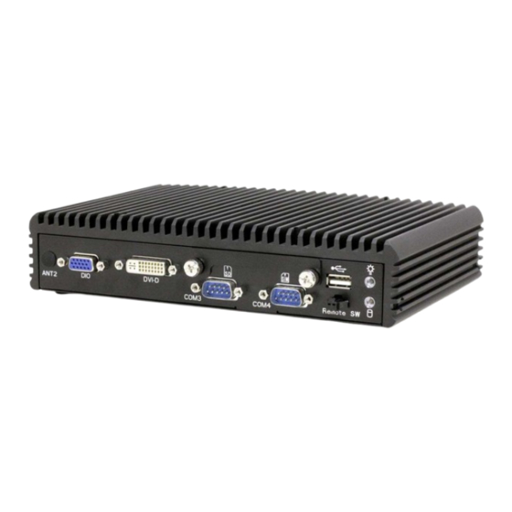
Chapter 1 Introduction 1-2. SYSTEM ILLUSTRATION Front View DVI-D ANT2 COM3 COM4 Remote SW Rear View GND VCC DVI-I Reset LAN2 LAN1 COM2 COM1 ANT1 Top View Quarter View 217.50 ′ Page: 1-3 SE-8124 USER S MANUAL... - Page 10 Chapter 1 Introduction Side View 140.60 ′ Page: 1-4 SE-8124 USER S MANUAL...
-
Page 11: System Specifications
2 x RJ45 connector with PoE support Wake on LAN/ Power ON/OFF 1x power button switch (rear), 1x 2pin connector for remote power button (front) Reset 1x reset (rear) ′ Page: 1-5 SE-8124 USER S MANUAL... - Page 12 -30~60°C (-22~140°F) with wide temp. peripherals w/o PoE (w/o Audio) (E3845 only) -30~55 °C (-22~131°F) with wide temp. peripherals with PoE (w/o Audio) (E3845 only) Storage Temp. -30 ~ 80°C (-22~ 176°F) Humidity Operating: 10 ~ 90%, Storage: 10~95%RH ′ Page: 1-6 SE-8124 USER S MANUAL...
-
Page 13: Safety Precautions
Always disconnect power when the system is not in use. Disconnect power when you change any hardware devices. For instance, when you connect a jumper or install any cards, a surge of power may damage the electronic components or the whole system. ′ Page: 1-7 SE-8124 USER S MANUAL... -
Page 14: Jumper & Connector Quick Reference Table
CHAPTER HARDWARE CONFIGURATION ** QUICK START ** Helpful information describes the jumper & connector settings, and component locations. Section includes: Jumper & Connector Quick Reference Table Component Locations Configuration and Jumper settings Connector’s Pin Assignments Page 2-1... -
Page 15: Pwr In Connector
Backlight Level Selection Connector JP_BLEN1 Clear CMOS Data Selection Panel Resolution Selection JP4, JP5 LVDS VCC Selection DVI-D Enable Selection JP34, JP35 DVI-D HPD Enable Selection JP37 Power Mode Selection JP39 DDV Selection JP13 Page: 2-2 ′ SE-8124 USER S MANUAL... - Page 16 JDIO1 DIMM1 INV1 JPOE1 JP_BLEN1 SLOT2 SLOT1 JP39 LVDS1 SATA_PWR1 JP10 JLPC1 SATA1 COM6 COM5 COM4 COM3 JP35 JP37 JP34 USB3 LED1 BAT1 DIO1 DVI1 SE-8124 Connectors, Jumpers and Components Locations - Front ′ Page: 2-3 SE-8124 USER S MANUAL...
- Page 17 Chapter 2 Hardware Configuration SE-8124 Connectors, Jumpers and Components Locations - Rear Page: 2-4 ′ SE-8124 USER S MANUAL...
- Page 18 PIN1 & PIN2 to create one setting by shorting. You can either connect PIN2 & PIN3 to create another setting. The same jumper diagrams are applied all through this manual. The figure below shows what the manual diagrams look and what they represent. ′ Page: 2-5 SE-8124 USER S MANUAL...
- Page 19 Jumper Block looks like this JUMPER SETTINGS 2 pin Jumper close(enabled) Looks like this 3 pin Jumper 2-3 pin close(enabled) Looks like this Jumper Block 1-2 pin close(enabled) Looks like this Page: 2-6 ′ SE-8124 USER S MANUAL...
- Page 20 The pin assignments are as follows: ASSIGNMENT PWRI(12~24V) CN_POWER1 2-5.COM PORT & CONNECTOR COM1/COM2 : RS-232/422/485, default RS-232 The pin assignments are as follows: COM1/COM2/COM3/ COM4/COM5/COM6 ASSIGNMENT RS-232 RS-422 RS-485 DCD# RS-485- RS-485+ DTR# DSR# RTS# CTS# ′ Page: 2-7 SE-8124 USER S MANUAL...
- Page 21 ASSIGNMENT COM3_DCD_C COM3_DSR_C COM3_RX_C COM3_RTS_C COM3_TX_C COM3_CTS_C COM3_DTR_C COM3_RI_C COM4: ASSIGNMENT PIN ASSIGNMENT COM4_DCD_C COM4_DSR_C COM4_RX_C COM4_RTS_C COM4_TX_C COM4_CTS_C COM4_DTR_C COM4_RI_C COM5: ASSIGNMENT PIN ASSIGNMENT COM5_DCD_C COM5_DSR_C COM5_RX_C COM5_RTS_C COM5_TX_C COM5_CTS_C COM5_DTR_C COM5_RI_C Page: 2-8 ′ SE-8124 USER S MANUAL...
- Page 22 Chapter 2 Hardware Configuration COM6: ASSIGNMENT ASSIGNMENT COM6_DCD_C COM6_DSR_C COM6_RX_C COM6_RTS_C COM6_TX_C COM6_CTS_C COM6_DTR_C COM6_RI_C Note: COM1/2 connectors are selectable for RI, +5V or +12V.For more information, please refer to COM PORT & VOLTAGE SELECTION. ′ Page: 2-9 SE-8124 USER S MANUAL...
- Page 23 (default) JPCOM1 JPCOM2 VCC12 JPCOM1 JPCOM2 VCC5V JPCOM1 JPCOM2 Note: The manufacturing default is RI 2-7.USB Connector USB2: Internal USB Connector The pin assignment is as follows: PIN ASSIGNMENT VCC5V USBC2N USBC2P USB2 Page: 2-10 ′ SE-8124 USER S MANUAL...
- Page 24 USB4: Internal USB Connector The pin assignment is as follows: ASSIGNMENT VCC5V USBC4N USB4 USBC4P USB5: Internal USB3.0 Connector The pin assignment is as follows: ASSIGNMENT VCC5V USBB_DM USBB_DP USB5 U3RXNDN1 U3RXNDP1 U3TXDN1 U3TXDP1 ′ Page: 2-11 SE-8124 USER S MANUAL...
-
Page 25: Lan Port
Left Side LED Green Color Blinking LAN Message Active No LAN Message Active Right Side LED Orange Color On 10/100 LAN Speed Indicator Red Color On Giga LAN Speed Indicator No LAN switch/ hub connected. Page: 2-12 ′ SE-8124 USER S MANUAL... - Page 26 Left Side LED Green Color Blinking LAN Message Active No LAN Message Active Right Side LED Orange Color On 10/100 LAN Speed Indicator Red Color on Giga LAN Speed Indicator No LAN switch/ hub connected. ′ Page: 2-13 SE-8124 USER S MANUAL...
-
Page 27: Dvi Connector
2-9. DVI CONNECTOR C1 C2 DVI2: DVI-I Connector The pin assignment is as follows: ASSIGNMENT C3 C5 C4 DVI_2- DVI2 DVI_2+ DVI_clock DVI_data CRT_VSYNC DVI_1- DVI_1+ DVI_HPD DVI_0- DVI_0+ DVI_Clock+ DVI_Clock- CRT_RED CRT_GREEN CRT_BLUE CRT_HSYNC Page: 2-14 ′ SE-8124 USER S MANUAL... - Page 28 Chapter 2 Hardware Configuration DVI1: DVI-D Connector The pin assignment is as follows: ASSIGNMENT C1 C2 DVI_2- DVI_2+ C3 C5 C4 DVI1 DVI_clock DVI_data DVI_1- DVI_1+ DVI_HPD DVI_0- DVI_0+ DVI_Clock+ DVI_Clock- ′ Page: 2-15 SE-8124 USER S MANUAL...
-
Page 29: Digital I/O Connector
ASSIGNMENT ASSIGNMENT DIN0 DIN1 DIN2 V5_SB DIN3 DOUT0 DOUT1 DOUT2 DOUT3 JDIO1: Digital I/O Connector. The pin assignments are as follows: ASSIGNMENT ASSIGNMENT V5_SB DIN1 DOUT1 DIN2 DOUT2 DIN3 DOUT3 DIN4 DOUT4 JDIO1 Page: 2-16 ′ SE-8124 USER S MANUAL... -
Page 30: Audio Connector
Chapter 2 Hardware Configuration 2-11. AUDIO CONNECTOR JAUDIO1: Audio Connectors The pin assignments are as follows: ASSIGNMENT MIC1L MIC1R JAUDIO1 LINEINL LINEINR LINEOUTL LINEOUTR ′ Page: 2-17 SE-8124 USER S MANUAL... -
Page 31: Sata & Sata Power Connector
Chapter 2 Hardware Configuration 2-12. SATA & SATA POWER CONNECTOR SATA1: Serial ATA Connector The pin assignments are as follows: ASSIGNMENT SATA1 HDD_Power1: Serial ATA Power Connector The pin assignments are as follows: ASSIGNMENT HDD_POWER1 VCC5V Page: 2-18 ′ SE-8124 USER S MANUAL... -
Page 32: Lvds Connector
The pin assignments are as follows: ASSIGNMENT ASSIGNMENT +3.3V/+5V LVDS_CLKBM LVDS_CLKBP LVDS_YBM2 LVDS_YBP2 LVDS_YBM1 LVDS_YBP1 LVDS_YBP3 LVDS_YBM3 LVDS_YBP0 LVDS_YBM0 LVDS_CLKAP LVDS_CLKAM LVDS_YAP2 LVDS_YAM2 LVDS_YAP1 LVDS_YAM1 LVDS_ YAP0 LVDS_YAM0 LVDS_YAP3 LVDS_YAM3 +3.3V/+5V +3.3V/+5V LVDS1 ′ Page: 2-19 SE-8124 USER S MANUAL... -
Page 33: Inverter Connector
Chapter 2 Hardware Configuration 2-14. INVERTER CONNECTOR INV1: Inverter Connector The pin assignments are as follows: ASSIGNMENT ASSIGNMENT V5P0A V5P0A USB_DM VCC12 USB_DN VCC12 VCC12 INV_EN VCC12 VCC12 HDD_LED PWR_LED Backlight PWM VCC5 INV1 Page: 2-20 ′ SE-8124 USER S MANUAL... -
Page 34: Backlight Level Selection Connector
Chapter 2 Hardware Configuration 2-15. Backlight Level Selection Connector JP_BLEN1: Backlight Level Selection Connector The selections are as follows: SELECTION JUMPER SETTING JUMPER ILLUSTRATION 3.3V (Default) JP_BLEN1 JP_BLEN1 Note: Manufacturing default is 3.3V. ′ Page: 2-21 SE-8124 USER S MANUAL... -
Page 35: Clear Cmos Data Selection
Chapter 2 Hardware Configuration 2-16. Clear CMOS DATA SELECTION JP2: Clear CMOS Data Selection Connector The selections are as follows: SELECTION JUMPER SETTINGS JUMPER ILLUSTRATION Normal (default) Clear CMOS Note: Manufacturing Default is normal Page: 2-22 ′ SE-8124 USER S MANUAL... -
Page 36: Panel Resolution Selection
JP4, JP5: Panel Resolution Selection Connectors The selections are as follows: Panel Resolution Jumper Setting JP4: 4-6,3-5 800x600 JP5: 4-6,3-5 JP4: 4-6,3-5 1024x768 JP5: 4-6,1-3 JP4: 4-6,3-5 1024x768 JP5: 2-4,3-5 JP4: 2-4,3-1 1920x1080 JP5: 2-4,3-5 ′ Page: 2-23 SE-8124 USER S MANUAL... -
Page 37: Lvds Vcc Selection
Chapter 2 Hardware Configuration 2-18. LVDS VCC Selection JP6: LVDS VCC Selection The selections are as follows: SELECTION JUMPER SETTING JUMPER ILLUSTRATION 3.3V (Default) Note: Manufacturing default is 3.3V. Page: 2-24 ′ SE-8124 USER S MANUAL... -
Page 38: Dvi-D Enable Selection
Chapter 2 Hardware Configuration 2-19. DVI-D ENABLE SELECTION JP34/JP35: DVI-D Enable Selection The selections are as follows: SELECTION JUMPER SETTING JUMPER ILLUSTRATION DVI-D Enable (Default) JP34/JP35 DVI-D Disable JP34/JP35 Note: Manufacturing Default is DVI-D Enable ′ Page: 2-25 SE-8124 USER S MANUAL... -
Page 39: Dvi-D Hpd Enable Selection
Note: Manufacturing Default is DVI-D HPD Enable 2-21. POWER MODE SELECTION JP39: Power Mode Selection The selections are as follows: SELECTION JUMPER SETTING JUMPER ILLUSTRATION AT Mode JP39 ATX Mode (Default) JP39 Note: Manufacturing default is ATX Mode. Page: 2-26 ′ SE-8124 USER S MANUAL... -
Page 40: Ddc Selection
SELECTION JUMPER SETTING JUMPER ILLUSTRATION VGA DDC JP13 DVI-I DDC JP13 Note: 1. Manufacturing default is DVI-I DDC. 2. Please set JP13 to VGA DDC if connecting VGA & DVI-D as dual display. ′ Page: 2-27 SE-8124 USER S MANUAL... -
Page 41: Chapter 3 Software Utilities
SOFTWARE CHAPTER UTILITIES This chapter comprises the detailed information of VGA driver, LAN driver, Sound driver and Card Reader driver. The following sections are included: Introduction ® Intel Chipset Software Installation Utility Intel ® Trusted Execution Engine Driver installation ... -
Page 42: Introduction
Enclosed with our SE-8124 package, you will find a DVD ROM disk containing all types of drivers we have. As a SE-8124 user, you will only need some of files contained in the DVD ROM disk, please take note of the following chart:... -
Page 43: Intel ® Chipset Software Installation Utility
Click infinst_autol.exe file for utility installation. Follow the instructions on the screen to complete the installation. Once installation is completed, shut down the system and restart in order for the changes to take effect. Page:3-3 ′ SE-8124 USER S MANUAL... -
Page 44: Intel ® Trusted Execution Engine Driver Installation
3-3-2. Installation Instructions for Windows 7/ 8.1 Insert the driver disk into a DVD ROM device. Under Windows system, go to the directory where the driver is located. Run the application with administrative privileges. Page:3-4 ′ SE-8124 USER S MANUAL... -
Page 45: Intel ® Kernel-Mode Driver Framework Driver Installation
To install the utility, simply follow the following steps: Insert the driver disk into a DVD ROM device. Under Windows system, go to the directory where the driver is located. Run the application with administrative privileges. Page:3-5 ′ SE-8124 USER S MANUAL... -
Page 46: Intel ® Mailbox Interface Device Driver
To install the utility, simply follow the following steps: Insert the driver disk into a DVD ROM device. Under Windows system, go to the directory where the driver is located. Run the application with administrative privileges. Page:3-6 ′ SE-8124 USER S MANUAL... - Page 47 To install the utility, simply follow the following steps: Insert the driver disk into a DVD ROM device. Under Windows system, go to the directory where the driver is located. Run the application with administrative privileges. Page:3-7 ′ SE-8124 USER S MANUAL...
-
Page 48: Vga Driver Utility
Chapter 3 Software Utilities 3-7. VGA DRIVER UTILITY The VGA interface is embedded with our SE-8124 system to support CRT display. The following illustration briefly shows you the content of VGA driver in D:\Driver\VGA. Win 7 Series Win 8.1 3-7-1. Installation of VGA Driver Start the computer (Win 7). -
Page 49: Lan Driver Utility
Chapter 3 Software Utilities 3-8 LAN DRIVER UTILITY The SE-8124 is enhanced with LAN function that can support various network adapters. The content of the LAN driver is found as follows: Win 7 Series Win 8.1 For more details on Installation procedure, please refer to Readme.txt file found on LAN DRIVER UTILITY. -
Page 50: Sound Driver Utility
Click on [Next] to continue the procedure. If the Windows popup "Windows can't verify the publisher of this driver software" message, press "Install this driver software anyway" to continue the installation. Finally, select to restart the system and press [Finish] to complete the installation. Page:3-10 ′ SE-8124 USER S MANUAL... -
Page 51: Card Reader Driver Utility
Open the Device/Card Reader folder and click the hotfix driver Windows6.1- KB2732471-v2-x64.msu on Win 7/WES7 64 bit after you restart the system. Note: Execute Windows on-line update after the card reader driver installation is finished on WES7. Page:3-11 ′ SE-8124 USER S MANUAL... -
Page 52: Chapter 4 System Installation
SYSTEM CHAPTER INSTALLATION This chapter shows how to install system for SE-8124. Section includes: Removing the bottom case HDD Installation SO-DIMM Installation Wireless LAN or 3G module Installation PoE Board Installation Page: 4-1... -
Page 53: Removing The Bottom Case
Please make sure the system is powered off and disconnected from the power sources before removing the bottom case to prevent electric shock or system damage. Locate the 6 screws on the bottom case Page:4-2 SE-8124 USER ′ S MANUAL... - Page 54 Chapter 4 System Installation Remove the 6 screws on the bottom case Remove the bottom case Page:4-3 SE-8124 USER ′ S MANUAL...
-
Page 55: Hdd Installation
Chapter 4 System Installation 4.2 HDD Installation Remove the bottom case Remove the 2 screws of HDD drive bay Page:4-4 SE-8124 USER ′ S MANUAL... - Page 56 Chapter 4 System Installation Paste thermal pad on HDD PCB (drive bay side) Put the HDD on the drive bay correctly Page:4-5 SE-8124 USER ′ S MANUAL...
- Page 57 Chapter 4 System Installation Fasten 4 HDD screws to fix HDD on the drive bay Plug SATA & HDD power cables on the mother board Page:4-6 SE-8124 USER ′ S MANUAL...
- Page 58 Chapter 4 System Installation Plug SATA & HDD power cable into HDD and put HDD & drive bay on the chassis Fasten the 2 screws of HDD drive bay Page:4-7 SE-8124 USER ′ S MANUAL...
-
Page 59: So-Dimm Installation
Chapter 4 System Installation 4.3 SO-DIMM Installation Remove the bottom case Remove the 2 screws & SATA/power cables of HDD drive bay Page:4-8 SE-8124 USER ′ S MANUAL... - Page 60 Chapter 4 System Installation Remove SATA/power cables on the mother board Locate the SO-DMM socket SO-DIMM Page:4-9 SE-8124 USER ′ S MANUAL...
- Page 61 Chapter 4 System Installation Prepare SO-DIMM and SO-DIMM heatsinks Paste SO-DIMM heatsinks on the 2 sides of SO-DIMM Page:4-10 SE-8124 USER ′ S MANUAL...
- Page 62 Chapter 4 System Installation Insert the SO-DIMM into the socket at 20~30 degrees angle Gently push the rear of the SO-DIMM down until it’s clipped into place and secure the SO-DIMM in the socket. Page:4-11 SE-8124 USER ′ S MANUAL...
-
Page 63: Wireless Lan Or 3G Module Installation
4.4 Wireless LAN or 3G module Installation A. Full-size mini-PCIe slot 1. If a half-size mini-PCIe module, connect it with half-size to full-size mini-PCIe bracket by 2 screws before installation Locate the full size mini-PCIe slot Page:4-12 SE-8124 USER ′ S MANUAL... - Page 64 Chapter 4 System Installation Insert the mini-PCIe module into the full-size mini-PCIe slot Figure 3a. Half-size mini-PCIe module Figure3b. Full-size mini-PCIe module Page:4-13 SE-8124 USER ′ S MANUAL...
- Page 65 Chapter 4 System Installation Fasten the 2 screws of full-size mini-PCIe slot Figure 4a. Half-size mini-PCIe module Figure 4b. Half-size mini-PCIe module Page:4-14 SE-8124 USER ′ S MANUAL...
- Page 66 Chapter 4 System Installation B. Half-size mini-PCIe slot Locate the half size mini-PCIe slot Insert the mini-PCIe module into the half-size mini-PCIe slot Page:4-15 SE-8124 USER ′ S MANUAL...
- Page 67 Chapter 4 System Installation Fasten the 2 screws of half-size mini-PCIe slot Page:4-16 SE-8124 USER ′ S MANUAL...
-
Page 68: Poe Board Installation
Chapter 4 System Installation 4.5. PoE Board Installation 1. Connect the PoE LED cable on PoE board 2. Put PoE board right on the PoE connector Page:4-17 SE-8124 USER ′ S MANUAL... - Page 69 Chapter 4 System Installation 3. Fasten 2 screws of PoE board Page:4-18 SE-8124 USER ′ S MANUAL...
- Page 70 CHAPTER BIOS SETUP This chapter describes how to set up the AMI BIOS. The following topics are included: Introduction Accessing Setup Main Advanced Chipset Security Boot Save & Exit Page: 5-1...
-
Page 71: Chapter 5 Ami Bios Setup
Chapter 5 AMI BIOS SETUP 5.1 Introduction The board SE-8124 uses an AMI Aptio BIOS that is stored in the Serial Peripheral Interface Flash Memory (SPI Flash) and can be updated. The SPI Flash contains the BIOS Setup program, Power-On Self-Test (POST), the PCI auto-configuration utility, LAN EEPROM information, and Plug and Play support. - Page 72 The BIOS Setup program can be used to view and change the BIOS settings for the computer. The BIOS Setup program is accessed by pressing the <Del> or <ESC> key after the POST memory test begins and before the operating system boot begins. The settings are shown below. ′ Page:5-3 SE-8124 USER S MANUAL...
-
Page 73: Accessing Setup
As long as this message is present on the screen you may press the <Del> key to access the Setup program. In a moment, the main menu of the Aptio Setup Utility will appear on the screen. Page:5-4 ′ SE-8124 USER S MANUAL... - Page 74 Chapter 5 AMI BIOS SETUP The Main menu screens of Bay Trail-D and Bay Trail-I platforms are shown respectively as below: For Bay Trail-D Platform ′ Page:5-5 SE-8124 USER S MANUAL...
- Page 75 You may move the cursor by up/down keys to highlight the individual menu items. As you highlight each item, a brief description of the highlighted selection will appear at the bottom of the screen. Page:5-6 ′ SE-8124 USER S MANUAL...
-
Page 76: Main
No changeable options Displays the current Sec RC version. TXE Firmware Version No changeable options Displays the current TXE Version System Language English BIOS Setup language. System Date month, day, year Specifies the current date. ′ Page:5-7 SE-8124 USER S MANUAL... -
Page 77: Advanced
System Super IO Chip Configuration. Hardware Monitor Sub-Menu Monitor hardware status F81866 MISC Sub-Menu F81866 related functions. CPU Configuration Sub-Menu CPU Configuration. Parameters. PPM Configuration Sub-Menu PPM Configuration. Parameters. IDE Configuration Sub-Menu SATA Configuration Parameters. Page:5-8 ′ SE-8124 USER S MANUAL... - Page 78 Description/Purpose OS Selection Sub-Menu OS selection settings. LPSS & SCC Configuration Sub-Menu LPSS & SCC Configuration Setting Configures Option ROM execution, boot CSM Configuration Sub-Menu options filters, etc. USB Configuration Sub-Menu USB Configuration Parameters. ′ Page:5-9 SE-8124 USER S MANUAL...
- Page 79 OS. ACPI Sleep State - Suspend Disabled Specifies the ACPI sleep state. - S3 Only (Suspend to RAM) Suspend Disabled disables ACPI sleep feature. S3 allows the platform to enter Suspend to RAM mode. Page:5-10 ′ SE-8124 USER S MANUAL...
- Page 80 Serial Port 1 Configuration Sub-menu Sets Parameters for COMA. Serial Port 2 Configuration Sub-menu Sets Parameters for COMB. Serial Port 3 Configuration Sub-menu Sets Parameters for COMC. Serial Port 4 Configuration Sub-menu Sets Parameters for COMD. ′ Page:5-11 SE-8124 USER S MANUAL...
- Page 81 Chapter 5 AMI BIOS SETUP BIOS Setting Options Description/Purpose Serial Port 5 Configuration Sub-menu Set Parameters for COME Serial Port 6 Configuration Sub-menu Set Parameters for COMF Page:5-12 ′ SE-8124 USER S MANUAL...
- Page 82 Displays the current settings of serial port 1. Change Settings - Auto Selects IRQ and I/O resource - IO=3F8h; IRQ=4 settings for the serial port 1. - IO=3F8h; IRQ=3,4,5,6,7,9,10,11,12 - IO=2F8h; IRQ=3,4,5,6,7,9,10,11,12 - IO=3E8h; IRQ=3,4,5,6,7,9,10,11,12 - IO=2E8h; IRQ=3,4,5,6,7,9,10,11,12 ′ Page:5-13 SE-8124 USER S MANUAL...
- Page 83 Displays the current settings of serial port 2. Change Settings - Auto Selects IRQ and I/O resource - IO=2F8h; IRQ=3 settings for the serial port 2. - IO=3F8h; IRQ=3,4,5,6,7,9,10,11,12 - IO=2F8h; IRQ=3,4,5,6,7,9,10,11,12 - IO=3E8h; IRQ=3,4,5,6,7,9,10,11,12 - IO=2E8h; IRQ=3,4,5,6,7,9,10,11,12 Page:5-14 ′ SE-8124 USER S MANUAL...
- Page 84 Displays the current settings of serial port 3. Change Settings - Auto Selects IRQ and I/O resource - IO=3E8h; IRQ=7 settings for the serial port 3. - IO=3F8h; IRQ=3,4,5,6,7,9,10,11,12 - IO=2F8h; IRQ=3,4,5,6,7,9,10,11,12 - IO=3E8h; IRQ=3,4,5,6,7,9,10,11,12 - IO=2E8h; IRQ=3,4,5,6,7,9,10,11,12 ′ Page:5-15 SE-8124 USER S MANUAL...
- Page 85 Displays the current settings of serial port 5. Change Settings - Auto Selects IRQ and I/O resource - IO=2E8h; IRQ=10 settings for the serial port 5. - IO=3F8h; IRQ=3,4,5,6,7,9,10,11,12 - IO=2F8h; IRQ=3,4,5,6,7,9,10,11,12 - IO=3E8h; IRQ=3,4,5,6,7,9,10,11,12 - IO=2E8h; IRQ=3,4,5,6,7,9,10,11,12 Page:5-16 ′ SE-8124 USER S MANUAL...
- Page 86 Displays the current settings of serial port 5. Change Settings - Auto Select IRQ and I/O resource - IO=2E8h; IRQ=5 settings for the serial port 5. - IO=3F8h; IRQ=3,4,5,6,7,9,10,11,12 - IO=2F8h; IRQ=3,4,5,6,7,9,10,11,12 - IO=3E8h; IRQ=3,4,5,6,7,9,10,11,12 - IO=2E8h; IRQ=3,4,5,6,7,9,10,11,12 ′ Page:5-17 SE-8124 USER S MANUAL...
- Page 87 Displays the current settings of serial port 6 Change Settings - Auto Select IRQ and I/O resource - IO=2E8h; IRQ=11 settings for the serial port 6. - IO=3F8h; IRQ=3,4,5,6,7,9,10,11,12 - IO=2F8h; IRQ=3,4,5,6,7,9,10,11,12 - IO=3E8h; IRQ=3,4,5,6,7,9,10,11,12 - IO=2E8h; IRQ=3,4,5,6,7,9,10,11,12 Page:5-18 ′ SE-8124 USER S MANUAL...
- Page 88 Displays the voltage level of the +VCORE in supply. 5VSB No changeable options Displays the voltage level of the +VSB5 in supply. VCC5 No changeable options Displays the voltage level of the + VCC5 in supply. ′ Page:5-19 SE-8124 USER S MANUAL...
- Page 89 Displays the voltage level of the + VCC3 in supply. VSB3V No changeable options Displays the voltage level of the standby VCC3 in supply. VBAT No changeable options Displays the voltage level of the battery in supply. Page:5-20 ′ SE-8124 USER S MANUAL...
- Page 90 - RS232 Select RS232 or RS422 or RS485 for - RS422 the COM1 port. - RS485 COM2 mode Selection - RS232 Select RS232 or RS422 or RS485 for - RS422 the COM2 port. - RS485 ′ Page:5-21 SE-8124 USER S MANUAL...
- Page 91 No changeable options Reports if 64-bit is supported by the processor. Limit CPUID Maximum - Disabled Enables for legacy operating systems to boot - Enabled processors with extended CPUID functions. Set disable for Win XP. Page:5-22 ′ SE-8124 USER S MANUAL...
- Page 92 No changeable options Displays the size of L1 Data Cache. L1 Code Cache No changeable options Displays the size of L1 Code Cache. L2 Cache No changeable options Displays the size of L2 Cache. ′ Page:5-23 SE-8124 USER S MANUAL...
- Page 93 BIOS Setting Options Description/Purpose L3 Cache No changeable options Displays size of L3 Cache. 5.4.6 Advanced – PPM Configuration PPM Configuration Screen BIOS Setting Options Description/Purpose EIST - Disabled Enables/Disables Intel SpeedStep. - Enabled Page:5-24 ′ SE-8124 USER S MANUAL...
- Page 94 Serial-ATA Port 0 - Disabled Enables or disables SATA port 0 - Enabled Device. SATA Port 0 [drive] Displays the drive installed on this SATA port 0. Shows [Empty] if no drive is installed. ′ Page:5-25 SE-8124 USER S MANUAL...
- Page 95 Select Windows 8.x or Windows 7 - Windows 7 Operating System. OS Selection: For Windows 8.x (64Bit), it is recommended to choose GOP VGA driver instead of Legacy BIOS. Please change settings under Advanced\ CSM\ Configuration\ Video\ select UEFI. Page:5-26 ′ SE-8124 USER S MANUAL...
- Page 96 Chapter 5 AMI BIOS SETUP 5.4.9 Advanced – LPSS & SCC Configuration LPSS & SCC Configuration Screen BIOS Setting Options Description/Purpose LPSS & SCC Device Mode - ACPI mode LPSS & SCC Device mode Settings - PCI mode ′ Page:5-27 SE-8124 USER S MANUAL...
- Page 97 Sets the display mode for Option ROM - Keep Current messages. Boot option filter - UEFI and Legacy This option controls what kind of - Legacy only devices system can boot. - UEFI only Page:5-28 ′ SE-8124 USER S MANUAL...
- Page 98 Controls the execution of UEFI and - UEFI Legacy Video. - Legacy Other PCI devices - Do not launch Determines OpROM execution policy - UEFI for devices other than Network, Storage, - Legacy or Video. ′ Page:5-29 SE-8124 USER S MANUAL...
- Page 99 XHCI hand-off support. EHCI Hand-off - Disabled This is a workaround for OSes without - Enabled EHCI hand-off support. USB Mass Storage Driver - Disabled Enable/Disable USB mass storage driver Support. - Enabled support. Page:5-30 ′ SE-8124 USER S MANUAL...
- Page 100 1 to 40 seconds in one second increment. Mass Storage Devices: - Auto Displays the device name and choose the - Floppy device emulation type. - Force FDD - Hard Disk - CD-ROM ′ Page:5-31 SE-8124 USER S MANUAL...
-
Page 101: Chipset
Chapter 5 AMI BIOS SETUP 5.5 Chipset Chipset Screen BIOS Setting Options Description/Purpose North Bridge Sub-menu Sets Parameter for Panther Point (North Bridge) configuration. South Bridge Sub-menu Sets Parameter for Ivy Bridge (South Bridge) configuration. Page:5-32 ′ SE-8124 USER S MANUAL... - Page 102 Intel IGD Configuration Sub-menu Configures Intel IGD Settings. Boot Display Control Sub-menu Boot Display Control. Memory Information No changeable options Displays the DRAM information on platform. Total Memory No changeable options Displays the DRAM size. ′ Page:5-33 SE-8124 USER S MANUAL...
- Page 103 (IGD) when selected as the Primary Video Adaptor. Disabled: Always disable IGD" IGD Turbo Enable - Enabled Enables or disables IGD Turbo - Disabled GFX Boost - Enabled Enables or disables GFX Boost accelerated - Disabled graphics processing Page:5-34 ′ SE-8124 USER S MANUAL...
- Page 104 Chapter 5 AMI BIOS SETUP BIOS Setting Options Description/Purpose DVMT Pre-Allocated - 64M Select DVMT 5.0 Pre-Allocated (Fixed) - 96M Graphics Memory size used by the Internal - 128M Graphics Device. - 256M - 512M ′ Page:5-35 SE-8124 USER S MANUAL...
- Page 105 Selects the Video Device which will be Display - DVI-I activated during POST. - DVI-D - LVDS Secondary IGFX - VBIOS Default Selects the Video Device which will be Boot Display - DVI-I activated during POST. - DVI-D - LVDS Page:5-36 ′ SE-8124 USER S MANUAL...
- Page 106 Power Off keeps the power off till the power button is pressed. Power On makes system power on after restores AC power to the board. Last State brings system back to the last power state before AC remove. ′ Page:5-37 SE-8124 USER S MANUAL...
- Page 107 Enables or Disables USB port 0. - Enabled USB Port 1 - Disabled Enables or Disables USB port 1. - Enabled USB Port 2 - Disabled Enables or Disables USB port 2. - Enabled Page:5-38 ′ SE-8124 USER S MANUAL...
- Page 108 Enables or Disables PCI Express port 0. - Enabled Speed - Auto Selects PCI Express port 0 speed. - Gen1 - Gen2 PCI Express Port 1 - Disabled Enabled or Disabled PCI Express port 1. - Enabled ′ Page:5-39 SE-8124 USER S MANUAL...
-
Page 109: Security
- Gen2 5.6 Security Security Screen BIOS Setting Options Description/Purpose Administrator Password Password can be 3-20 Specifies the administrator password. alphanumeric characters. User Password Password can be 3-20 Specifies the user password. alphanumeric characters. Page:5-40 ′ SE-8124 USER S MANUAL... -
Page 110: Boot
Hard Drive BBS Priorities. Hard Drive BBS Priorities Sub-Menu Allows users to select the boot order of available drive(s) Network Device BBS Priorities Sub-Menu Sets the order of the legacy devices in the group. ′ Page:5-41 SE-8124 USER S MANUAL... - Page 111 Chapter 5 AMI BIOS SETUP Hard Drive BBS Priorities Screen BIOS Setting Options Description/Purpose Boot Option #1 - #n - [Drive(s)] Changes the boot order of available drive(s). - Disabled Page:5-42 ′ SE-8124 USER S MANUAL...
- Page 112 Chapter 5 AMI BIOS SETUP Network Device BBS Priorities Screen BIOS Setting Options Description/Purpose Boot Option #1 - #n - [Drive(s)] Sets the system boot order. - Disabled ′ Page:5-43 SE-8124 USER S MANUAL...
-
Page 113: Save & Exit
Saves the changes in NVRAM and resets. Reset Discard Changes and No changeable options Resets without saving any changes made in Reset BIOS settings. Restore Defaults No changeable options Loads the optimized defaults for BIOS settings. Page:5-44 ′ SE-8124 USER S MANUAL... - Page 114 Chapter 5 AMI BIOS SETUP BIOS Setting Options Description/Purpose Boot Override - [Drive(s)] Forces to boot from selected [drive(s)]. ′ Page:5-45 SE-8124 USER S MANUAL...
- Page 115 APPENDIX SYSTEM ASSEMBLY This appendix contains the exploded diagrams & part numbers of the SE-8124 system. Section includes: Exploded Diagram for Bottom Case Exploded Diagram for HDD Support Board Exploded Diagram for Front & Rear Case Exploded Diagram for Motherboard ...
-
Page 116: Appendix A System Assembly Exploded Diagram For Bottom Case
Appendix A System Assembly EXPLODED DIAGRAM FOR BOTTOM CASE Page: A-2 ′ SE-8124 USER S MANUAL... -
Page 117: Exploded Diagram For Hdd Support Board
Appendix A System Assembly EXPLODED DIAGRAM FOR HDD SUPPORT BOARD ′ Page: A-3 SE-8124 USER S MANUAL... - Page 118 Appendix A System Assembly EXPLODED DIAGRAM FOR FRONT & BACK CASE Page: A-4 ′ SE-8124 USER S MANUAL...
-
Page 119: Exploded Diagram For Motherboard
Appendix A System Assembly EXPLODED DIAGRAM FOR MOTHERBOARD ′ Page: A-5 SE-8124 USER S MANUAL... -
Page 120: Exploded Diagram For Heatsink
Appendix A System Assembly EXPLODED DIAGRAM FOR HEATSINK Page: A-6 ′ SE-8124 USER S MANUAL... - Page 121 APPENDIX TECHNICAL SUMMARY This section introduces you the maps concisely. Section includes: Block Diagram Interrupt Map I/O Map Memory Map Watchdog Timer Configuration Flash BIOS Update Page: B-1...
-
Page 122: Appendix B Technical Summary
Appendix B Technical Summary BLOCK DIAGRAM Page: B-2 ′ SE-8124 USER S MANUAL... -
Page 123: Interrupt Map
Microsoft ACPI-Compliant System (ISA) IRQ 94 Microsoft ACPI-Compliant System (ISA) IRQ 95 Microsoft ACPI-Compliant System (ISA) IRQ 96 Microsoft ACPI-Compliant System (ISA) IRQ 97 Microsoft ACPI-Compliant System (ISA) IRQ 98 Microsoft ACPI-Compliant System ′ Page: B-3 SE-8124 USER S MANUAL... - Page 124 Microsoft ACPI-Compliant System (ISA) IRQ 121 Microsoft ACPI-Compliant System (ISA) IRQ 122 Microsoft ACPI-Compliant System (ISA) IRQ 123 Microsoft ACPI-Compliant System (ISA) IRQ 124 Microsoft ACPI-Compliant System (ISA) IRQ 125 Microsoft ACPI-Compliant System Page: B-4 ′ SE-8124 USER S MANUAL...
- Page 125 Microsoft ACPI-Compliant System (ISA) IRQ 148 Microsoft ACPI-Compliant System (ISA) IRQ 149 Microsoft ACPI-Compliant System (ISA) IRQ 150 Microsoft ACPI-Compliant System (ISA) IRQ 151 Microsoft ACPI-Compliant System (ISA) IRQ 152 Microsoft ACPI-Compliant System ′ Page: B-5 SE-8124 USER S MANUAL...
- Page 126 Microsoft ACPI-Compliant System (ISA) IRQ 175 Microsoft ACPI-Compliant System (ISA) IRQ 176 Microsoft ACPI-Compliant System (ISA) IRQ 177 Microsoft ACPI-Compliant System (ISA) IRQ 178 Microsoft ACPI-Compliant System (ISA) IRQ 179 Microsoft ACPI-Compliant System Page: B-6 ′ SE-8124 USER S MANUAL...
- Page 127 High Definition Audio Controller (PCI) IRQ 23 Standard Enhanced PCI to USB Host Controller Note: The resource information is gathered by Windows 7 (the IRQ could be assigned differently depending on your OS). ′ Page: B-7 SE-8124 USER S MANUAL...
-
Page 128: I/O Map
Motherboard resources 0x00000067-0x00000067 Motherboard resources 0x00000070-0x00000070 Motherboard resources 0x00000070-0x00000070 System CMOS/real time clock 0x00000078-0x00000CF7 PCI bus 0x00000080-0x0000008F Motherboard resources 0x00000092-0x00000092 Motherboard resources 0x000000A0-0x000000A1 Programmable interrupt controller 0x000000A4-0x000000A5 Programmable interrupt controller 0x000000A8-0x000000A9 Programmable interrupt controller Page: B-8 ′ SE-8124 USER S MANUAL... - Page 129 Motherboard resources 0x00000680-0x0000069F Motherboard resources 0x00000A00-0x00000A0F Motherboard resources 0x00000A10-0x00000A1F Motherboard resources 0x00000A20-0x00000A2F Motherboard resources 0x00000D00-0x0000FFFF PCI bus 0x0000D000-0x0000D01F Ethernet Controller 0x0000D000-0x0000DFFF PCI standard PCI-to-PCI bridge 0x0000E000-0x0000E01F Ethernet Controller 0x0000E000-0x0000EFFF PCI standard PCI-to-PCI bridge ′ Page: B-9 SE-8124 USER S MANUAL...
- Page 130 0x0000F040-0x0000F043 Stamdard AHCI 1.0 Serial ATA Controller 0x0000F050-0x0000F057 Stamdard AHCI 1.0 Serial ATA Controller 0x0000F060-0x0000F063 Stamdard AHCI 1.0 Serial ATA Controller 0x0000F070-0x0000F077 Stamdard AHCI 1.0 Serial ATA Controller 0x0000F080-0x0000F087 Video Controller (VGA Compatible) Page: B-10 ′ SE-8124 USER S MANUAL...
-
Page 131: Memory Map
0xD0A17000-0xD0A17FFF SDA Standard Compliant SD Host Controller 0xD0A18000-0xD0A18FFF Motherboard resources 0xE0000000-0xEFFFFFFF High precision event timer Motherboard resources 0xFED00000-0xFED003FF Motherboard resources 0xFED01000-0xFED01FFF Motherboard resources 0xFED03000-0xFED03FFF Motherboard resources 0xFED04000-0xFED04FFF Motherboard resources 0xFED08000-0xFED08FFF 0xFED0C000-0xFED0FFFF Motherboard resources 0xFED1C000-0xFED1CFFF Motherboard resources ′ Page: B-11 SE-8124 USER S MANUAL... - Page 132 Appendix B Technical Summary MEMORY ASSIGNMENT Motherboard resources 0xFEE00000-0xFEEFFFFF Motherboard resources 0xFEF00000-0xFEFFFFFF 0xE0000-0xFFFFF PCI Express Root Complex Page: B-12 ′ SE-8124 USER S MANUAL...
-
Page 133: Watchdog Timer Configuration
To exit the Extended Function Mode, writing 0xAA to the EFER is required. Once the chip exits the Extended Function Mode, it is in the normal running mode and is ready to enter the configuration mode. ′ Page: B-13 SE-8124 USER S MANUAL... - Page 134 ;------ Select Logical Device 8 of watchdog timer -------------------------------------------- ;------ Set second as counting unit -------------------------------------------------------------- 0f5h not 08h ;------ Set timeout interval as 30seconds and start counting --------------------------------- 0f6h ;------ Exit the extended function mode -------------------------------------------------------- 0aah Page: B-14 ′ SE-8124 USER S MANUAL...
-
Page 135: Flash Bios Update
System will go into the BIOS setup menu. Select [Boot] menu. Select [Hard Drive BBS Priorities], set the USB bootable device to be the boot device. Press <F4> key to save configuration and exit the BIOS setup menu. ′ Page: B-15 SE-8124 USER S MANUAL... - Page 136 After BIOS update procedures is complete, the messages should be like the figure shown below. 5. User can restart the system and boot up with new BIOS now. Page: B-16 ′ SE-8124 USER S MANUAL...
- Page 137 Appendix B Technical Summary 6. Update is complete after restart. 7. Verify during following boot that the BIOS version displayed at initialization screen has changed. ′ Page: B-17 SE-8124 USER S MANUAL...
Need help?
Do you have a question about the SE-8124 and is the answer not in the manual?
Questions and answers