
Related Manuals for Samson 3371 Series


Summary of Contents for Samson 3371 Series
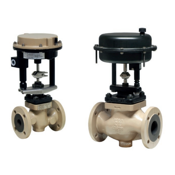
- Page 1 Type 3371 Pneumatic Actuator Actuator area: 120 and 350 cm² Type 3371 with 120 cm² actuator area Type 3371 with 350 cm² actuator area Mounting and Operating Instructions EB 8317 EN Edition November 2016...
- Page 2 Î For the safe and proper use of these instructions, read them carefully and keep them for later reference. Î If you have any questions about these instructions, contact SAMSON‘s After-sales Service Department (aftersalesservice@samson.de). The mounting and operating instructions for the devices are included in the scope of delivery.
-
Page 3: Table Of Contents
Contents Safety instructions and measures ..............5 Notes on possible severe personal injury ............7 Notes on possible personal injury ..............7 Notes on possible property damage ..............8 Markings on the device ................10 Actuator nameplate ..................10 Design and principle of operation ..............12 Direction of action ..................12 Signal pressure routing .................12 Fail-safe action ....................15 3.3.1... - Page 4 Contents 5.3.1 Increasing the actuator thrust ................29 5.3.2 Adapting the travel range ................29 Additional fittings ..................30 Operation ....................31 On/off service .....................31 Reversal of the direction of action ..............31 6.2.1 120 cm² version ..................32 6.2.2 350 cm² version ..................34 Version with travel stop .................36 6.3.1 Bottom travel stop (minimum travel) ...............36 6.3.2...
-
Page 5: Safety Instructions And Measures
SAMSON. SAMSON does not assume any liability for damage resulting from the failure to use the de- vice for its intended purpose or for damage caused by external forces or any other external factors. - Page 6 Î Check with the plant operator for details on further protective equipment. Revisions and other modifications Revisions, conversions or other modifications to the product are not authorized by SAMSON. They are performed at the user's own risk and may lead to safety hazards, for example. Fur- thermore, the product may no longer meet the requirements for its intended use.
-
Page 7: Notes On Possible Severe Personal Injury
The following documents apply in addition to these mounting and operating instructions: − Mounting and operating instructions for the mounted valve e.g. u EB 8111 for SAMSON Type 3321 Valve − Mounting and operating instructions for mounted valve accessories (positioner, solenoid valve etc.) −... -
Page 8: Notes On Possible Property Damage
Î Wear eye protection when working in close proximity to the control valve. Damage to health relating to the REACH regulation. If a SAMSON device contains a substance which is listed as being a substance of very high concern on the candidate list of the REACH regulation, this circumstance is indicat- ed on the SAMSON delivery note. - Page 9 Risk of actuator damage due to the use of unsuitable tools. Certain tools are required to work on the actuator. Î Only use tools approved by SAMSON (u AB 0100). Risk of actuator damage due to the use of unsuitable lubricants. The lubricants to be used depend on the actuator material. Unsuitable lubricants may corrode and damage the valve surface.
-
Page 10: Markings On The Device
9 Date of manufacture (month and year) Nameplate Fig. 1: Location of nameplate SAMSON 3371 Pneumatic Actuator 120 cm² See technical data for ambient temperature Model Var.-ID Serial no. Air supply max. SAMSON AG D-60314 Frankfurt Made in Germany Fig. 2: Example for nameplate EB 8317 EN... - Page 11 EB 8317 EN...
-
Page 12: Design And Principle Of Operation
Design and principle of operation 3 Design and principle of oper- tion on the top diaphragm case. With direc- tion of action "actuator stem extends", the ation compressed air is applied to the signal pres- The Type 3371 Pneumatic Actuators have an sure connection on the bottom diaphragm actuator area of either 120 or 350 cm². - Page 13 Design and principle of operation Mounting with crossbeam Mounting without crossbeam • • • • • • • • • • • • • Vent plug A16 Top diaphragm case Bottom diaphragm case A17 Crossbeam Actuator stem A18 Diaphragm A10 Spring A26 Collar nut A11 Rod A30/...
- Page 14 Design and principle of operation • • • • • • • • • • • • • • • • • • Top diaphragm case A21 Hexagon nut A51 Rod Bottom diaphragm case A25 Washer A54 Rod nut Diaphragm A27 Compressor A60 Plate Diaphragm plate...
-
Page 15: Fail-Safe Action
Design and principle of operation 3.3.2 Version with direction of 350 cm² version (see Fig. 4) action "actuator stem In the "actuator stem extends" version, the signal pressure is routed through the bottom retracts" (FE) signal pressure connection (S) to the bottom When the signal pressure is reduced or the diaphragm chamber and moves the actuator control signal fails, the springs move the ac-... - Page 16 Design and principle of operation Table 1: Mounting types (see Fig. 5 and Fig. 6) Actuator area 120 cm² 350 cm² Travel 15 mm 15 mm 30 mm Type ... Valve Nominal size DN 3321 15 to 50 Form B – – 3321 65 to 100 Form C Form C – 3321 –...
-
Page 17: Versions
Design and principle of operation 3.5 Versions − Version with handwheel The Type 3371 Actuators (120 cm²) can − Standard version of Type 3371 be fitted with an additional handwheel. (120 cm²) The handwheel is mounted on the top di- The housings of Type 3371 Pneumatic aphragm case (A1) and is used to adjust Actuators have an actuator area of the travel manually. - Page 18 Design and principle of operation Table 2: Technical data for Type 3371 Pneumatic Actuator Actuator area 120 cm² 350 cm² Rated travel 15 mm 30 mm Stem Stem Stem Stem Stem Stem Stem Stem Fail-safe action retracts retracts extends extends retracts extends retracts extends (FE) (FE) (FA) (FA) (FE)
-
Page 19: Measures For Preparation
2. Check the shipment for transportation Transport instructions damage. Report any damage to − Protect the actuator against external in- SAMSON and the forwarding agent fluences (e.g. impact). (refer to delivery note). − Do not damage the corrosion protection 4.1 Unpacking (paint, surface coatings). -
Page 20: Storage
− To keep elastomers in shape and to pre- − Avoid long storage times. vent cracking, do not bend them or hang − Contact SAMSON in case of different stor- them up. age conditions or long storage periods. − We recommend a storage temperature of 15 °C for elastomers. -
Page 21: Preparation For Installation
Measures for preparation 4.4 Preparation for installation Proceed as follows: Î Check the actuator for damage. Î Check to make sure that the type desig- nation, material, and temperature range of the actuator match the plant condi- tions. Î Check the pressure gauge installed on valve accessories to make sure it func- tions. -
Page 22: Mounting And Start-Up
Mounting and start-up 5 Mounting and start-up 5.1 Mounting the actuator onto the valve SAMSON control valves are delivered ready for use. In special cases, the valve and actu- ator are delivered separately and must be Note assembled on site. The procedure to mount −... - Page 23 Mounting and start-up Mounting with crossbeam Mounting without crossbeam • • • • • • • • • • • • • Vent plug A16 Top diaphragm case Bottom diaphragm case A17 Crossbeam Actuator stem A18 Diaphragm A10 Spring A26 Collar nut A11 Rod A30/ Stem connector clamps...
-
Page 24: 120 Cm² Version
Mounting and start-up 5.1.1 120 cm² version the plug stem and fasten it to the valve bonnet. Observe tightening torques. Mounting using crossbeam (Form B, see 5. "Stem extends" direction of action: Posi- Fig. 10) tion clamps of the stem connector (A30) and screw them tight. Observe tightening NOTICE torques. - Page 25 Mounting and start-up Mounting using rods (Form C, see Fig. 11) WARNING 1. Remove the stem connector clamps (A31) Crush hazard arising from moving parts. from the actuator. The actuator contains moving parts (actuator 2. Insert the rods (A11) into the bushings stem), which can injure hands or fingers if (A12) and place them in the correspond- inserted into the actuator.
-
Page 26: 350 Cm² Version
Mounting and start-up 5.1.2 350 cm² version screw them tight. Observe tightening torques. Mounting using rods (Form C, see Fig. 12) "Stem retracts" direction of action: ap- 1. Remove the clamps of the stem connector ply enough pressure to the top dia- from the actuator. phragm chamber to make the actuator stem touch the plug stem. -
Page 27: Changing The Mounting Type
Mounting and start-up 5.2 Changing the mounting 5.2.1 Changing the mounting type type to mounting using rods (Form B to Form C) The mounting type of actuators with 120 cm² actuator area can be changed subsequently. Note Note For mounting the rods, a plate (A60) and Table 1 provides an overview of the possible two bushings (A12) are required to adapt it combinations (Form B and Form C). -
Page 28: Changing The Mounting Type To Mounting Using A Crossbeam (Form C To Form B)
− The thrust is increased (only actuators (A17), two serrated lock washers (A28), and with "stem extends") two caps (A70) are required. − In combination with a SAMSON valve: 1. Remove the clamps of the stem connec- the actuator travel range can be adapted tor. -
Page 29: Increasing The Actuator Thrust
Adapting the travel Note range Actuators that have already been preloaded by SAMSON without mounting the valve are In some cases, the valve and actuator have labeled correspondingly. different rated travels. Depending on the di- Additionally, these actuators can be identi-... -
Page 30: Additional Fittings
Mounting and start-up 5.4 Additional fittings At half the valve travel, the operating range is between 1.4 and 1.85 bar. Vent plugs Vent plugs are screwed into the exhaust air ports of pneumatic and electropneumatic de- vices. They ensure that any exhaust air that forms can be vented to the atmosphere (to avoid excess pressure in the device). -
Page 31: Operation
Operation 6 Operation Max. Fail-safe Bench range supply action pressure WARNING 0.4 to 1.4 bar 4.4 bar Crush hazard arising from moving parts Actuator stem 1.4 to 2.3 bar 5.3 bar (actuator stem). retracts 1.5 to 2.1 bar 5.1 bar Do not insert hands or fingers into the yoke while the valve is in operation. -
Page 32: Reversal Of The Direction Of Action
6.2 Reversal of the direction of After reversal, the symbol and configuration ID on the nameplate are no longer valid. action Contact SAMSON to request a new name- The direction of action (and fail-safe action) plate. of pneumatic actuators can be changed. The fail-safe action is indicated on the nameplate 6.2.1... - Page 33 Operation 9. Place the springs (A10) in the bottom di- 4. Pull the actuator stem (A3) together with aphragm case (A2), centering them in the diaphragm plate (A14), diaphragm the intended recesses. (A18), and diaphragm plate (A13) out of the bottom diaphragm case (A2). 10.
-
Page 34: 350 Cm² Version
Operation 14. Mount the actuator on the valve (see sec- 6. Take the compressor (A27), diaphragm tion 5.1). plate (A5), and diaphragm (A4) off the actuator stem (A7) and place them back The actuator springs, which now push on again in the reverse order. against the diaphragm plate from above, cause the actuator stem to extend. - Page 35 Operation 2. Unscrew the nuts (A21) and bolts (A20) 11. Place the springs (A10) in the bottom di- on the diaphragm case. aphragm case (A2), centering them in the intended recesses. 3. Lift off the top diaphragm case (A1). 12. Place on the top diaphragm case (A1). 4.
-
Page 36: Version With Travel Stop
Operation 6.3.1 Bottom travel stop (min- 14. Affix a new nameplate with changed symbol and new configuration ID to the imum travel) actuator. 1. Loosen lock nut (A76) and remove cover 6.3 Version with travel stop (A75). 2. Loosen the lock nuts (A79). The Type 3371 Pneumatic Actuator 3. -
Page 37: Top Travel Stop (Maximum Travel)
(A66) depending on which way the handwheel is turned. This causes the spindle (A62) to either extend or retract. Note If you want to fit a handwheel to an actuator, contact SAMSON's After-sales Service de- partment. EB 8317 EN... -
Page 38: Servicing
Risk of actuator damage due to the use of Actuators are pressurized. Improper opening unsuitable tools. can lead to actuator components bursting. Only use tools approved by SAMSON Before starting any work on the actuator, de- (u AB 0100). pressurize all plant sections concerned and the actuator. -
Page 39: Replacing The Diaphragm
Servicing 7.1 Replacing the diaphragm 7. Place the new diaphragm on the dia- phragm plate (A13). Place on the dia- phragm plate (A14). 7.1.1 120 cm² version 8. Check the sealing element on the collar nut (A26). If necessary, renew it. 9. - Page 40 Servicing Mounting with crossbeam Mounting without crossbeam • • • • • • • • • • • • • Vent plug A16 Top diaphragm case Bottom diaphragm case A17 Crossbeam Actuator stem A18 Diaphragm A10 Spring A26 Collar nut A11 Rod A30/ Stem connector clamps...
-
Page 41: 350 Cm² Version
Servicing 2. Unscrew the nuts (A24) and bolts (A22) 15. Mount the actuator on the valve (see sec- on the diaphragm case. tion 5.1). 3. Lift off the top diaphragm case (A16). 7.1.2 350 cm² version 4. Pull the actuator stem (A3) together with the diaphragm plate (A14), diaphragm (A18), and diaphragm plate (A13) out of the bottom diaphragm case (A2). - Page 42 Servicing • • • • • • • • • • • • • • • • • • Top diaphragm case A20 Hexagon bolt A42 Dry bearing Bottom diaphragm case A21 Hexagon nut A50 Screw for rod (A51) Diaphragm A25 Washer A51 Rod Diaphragm plate...
- Page 43 Servicing 8. Place the compressor (A27) onto the ac- 3. Lift off the top diaphragm case (A1). tuator stem (A7). 4. Pull the actuator stem (A7) together with 9. Check the sealing element on the collar the diaphragm plate (A5) and dia- nut (A15).
-
Page 44: Preparation For Return Shipment
> Contact. 7.3 Ordering spare parts and operating supplies Contact your nearest SAMSON subsidiary or the SAMSON After-sales Service depart- ment for information on spare parts, lubri- cants, and tools. Spare parts See section 10.2 for details on spare parts. -
Page 45: Malfunctions
Depending on the operating conditions, check the actuator at certain intervals to prevent possible failure before it can occur. Operators are responsible for drawing up an inspection plan. SAMSON's After-sales Service department can support you to draw up an inspection plan for your plant. Troubleshooting... -
Page 46: Decommissioning And Disassembly
Decommissioning and disassembly 9 Decommissioning and disas- 9.2 Removing the actuator sembly from the valve 9.2.1 120 cm² version DANGER Risk of bursting in the actuator. For mounting using crossbeam (Form B) Actuators are pressurized. Improper opening can lead to actuator components bursting. 1. -
Page 47: 350 Cm² Version
Decommissioning and disassembly 9.3 Relieving the spring com- For mounting using rods (Form C) pression in the actuator 1. Put the control valve out of operation. See associated valve documentation. 1. Undo the short nuts and bolts on the dia- 2. Remove the clamps of the stem connector phragm cases. -
Page 48: Annex
You can reach the After-sales Service De- partment at aftersalesservice@samson.de. Addresses of SAMSON AG and its subsid- iaries The addresses of SAMSON AG, its subsid- iaries, representatives, and service facilities worldwide can be found on the SAMSON website, in all SAMSON product catalogs or on the back of these Mounting and Operat- ing Instructions. -
Page 49: Spare Parts
Annex 10.2 Spare parts Type 3371 Actuator with 120 cm² actuator area Vent plug Sleeve Bottom diaphragm case Retaining washer Radial shaft seal Protective cap Wiper ring Rod nut (hexagon nut) Dry bearing Spindle Actuator stem Sleeve Stopper 74.1 Dry bearing Label (preloading) 74.2 Radial shaft seal Nameplate... - Page 50 Type 3371 Actuator with Version with hand- 120 cm² actuator area wheel 65 68 7/8/9/10 EB 8317 EN...
- Page 51 Version with travel stop 74.2 74.1 Standard version 20/1 20/1 Mounting without cross- beam Mounting with crossbeam EB 8317 EN...
- Page 52 Annex Type 3371 Actuator with 350 cm² actuator area Top diaphragm case Bottom diaphragm case Diaphragm Diaphragm plate Actuator stem 10/11 Spring Stem connector clamp Stem connector clamp Screw Collar nut Vent plug Hexagon bolt Hexagon nut Hexagon bolt (preloading) Washer Compressor Washer Radial shaft seal Wiper ring...
- Page 53 Type 3371 Actuator with 350 cm² actuator area EB 8317 EN...
- Page 54 EB 8317 EN...
- Page 55 EB 8317 EN...
- Page 56 SAMSON AG · MESS- UND REGELTECHNIK Weismüllerstraße 3 · 60314 Frankfurt am Main, Germany Phone: +49 69 4009-0 · Fax: +49 69 4009-1507 EB 8317 EN samson@samson.de · www.samson.de...
Need help?
Do you have a question about the 3371 Series and is the answer not in the manual?
Questions and answers