Samson 4708 Series Mounting And Operating Instructions
Supply pressure regulators
Hide thumbs
Also See for 4708 Series:
- Mounting and operating instructions (26 pages) ,
- Mounting and operating instructions (36 pages)

Related Manuals for Samson 4708 Series


Summary of Contents for Samson 4708 Series
- Page 1 EB 8546 EN Translation of original instructions Type 4708-53 Type 4708-64 Type 4708-12 Type 4708 Supply Pressure Regulators Edition April 2020...
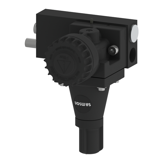
- Page 2 Note on these mounting and operating instructions These mounting and operating instructions assist you in mounting and operating the device safely. The instructions are binding for handling SAMSON devices. The images shown in these instructions are for illustration purposes only. The actual product may vary.
-
Page 3: Table Of Contents
Contents Safety instructions and measures ..............5 Notes on possible personal injury ..............7 Notes on possible property damage ..............7 Markings on the device .................8 Design and principle of operation ..............12 Versions ......................14 Technical data .....................15 Spare parts ....................17 Accessories ....................18 Dimensions in mm ..................19 Measures for preparation ................28 Unpacking ....................28 Storage .......................28... - Page 4 Contents Troubleshooting...................42 Decommissioning and removal ..............43 12.1 Decommissioning ..................43 12.2 Removing the supply pressure regulator ............43 12.3 Disposal ......................43 After-sales service ..................44 EB 8546 EN...
-
Page 5: Safety Instructions And Measures
SAMSON. SAMSON does not assume any liability for damage resulting from the failure to use the device for its intended purpose or for damage caused by external forces or any other external factors. - Page 6 Î Check with the plant operator for details on further protective equipment. Revisions and other modifications Revisions, conversions or other modifications of the product are not authorized by SAMSON. They are performed at the user's own risk and may lead to safety hazards, for example.
-
Page 7: Notes On Possible Personal Injury
Î Do not exceed the maximum permissible torques specified in these mounting and operating instructions. Risk of damage to the supply pressure regulator due to foreign particles entering it. Î Do not remove the protective film until immediately before mounting. Risk of damage to the supply pressure regulator due to improper storage. Î Observe the storage instructions. Contact SAMSON, if need be. EB 8546 EN... -
Page 8: Markings On The Device
Markings on the device 2 Markings on the device Article code Supply Pressure Regulator Type 4708- x Standard version Aluminum mounted parts, plastic body, with filter, without separate filter receptacle Aluminum mounted parts, plastic body, with transparent filter receptacle Completely of aluminum, no plastic parts Stainless steel version Completely of stainless steel, no plastic parts Stainless steel mounted parts, plastic body, with transparent filter... - Page 9 Markings on the device Supply Pressure Regulator Type 4708- x Further versions Manual/automatic switchover Filter for compressed air, aluminum body, transparent plastic filter receptacle Filter for compressed air, aluminum body and filter receptacle Filter for compressed air, stainless steel body, transparent plastic filter receptacle Filter for compressed air, stainless steel body and filter receptacle Connecting thread ISO-228/1-G ¼...
- Page 10 Markings on the device Supply Pressure Regulator Type 4708- x Filter Without in black plastic regulator body in transparent plastic receptacle (cannot be aligned) in aluminum receptacle (cannot be aligned) in stainless steel receptacle (cannot be aligned) Temperature range –25 to +70 °C (standard) –40 to +70 °C –50 to +70 °C Application...
- Page 11 EB 8546 EN...
-
Page 12: Design And Principle Of Operation
Design and principle of operation 3 Design and principle of oper- The compressed air at the inlet flows across the filter through the free cross-section be- ation tween the seat (1.1) and plug (1.2) and The supply pressure regulator is used to leaves the output with a reduced pressure supply pneumatic measuring and control depending on the plug position. - Page 13 Design and principle of operation 11 12.1 11.4 12.1 11.3 Body 11.1 1.1 Seat 1.2 Plug 1.3 Connecting bore 11.2 Plate 2.1 Diaphragm Cover 3.1 Venting bore Centering bushing Set point spring Set point screw Lock nut Filter cartridge 11.1 Screw 11.2 Cap 11.3 Shroud 11.4 Air deflector...
-
Page 14: Versions
Design and principle of operation 3.1 Versions Supply Pressure Regulator Type 4708- Standard version Aluminum filter without filter receptacle with plastic filter receptacle with aluminum filter receptacle Stainless steel version Stainless steel filter with stainless steel filter receptacle with plastic filter receptacle without filter receptacle Connection G ¼... -
Page 15: Technical Data
Design and principle of operation Supply Pressure Regulator Type 4708- Manual/automatic switchover Bypass for positioner Filter without pressure gauge Type 4708- Aluminum body and plastic filter receptacle Aluminum body and aluminum filter receptacle Stainless steel body and plastic filter receptacle Stainless steel body and stainless steel filter receptacle Note For details on the Type 4708-45 Supply Pressure Regulator (with increased air capacity), see EB 8546-1. - Page 16 Design and principle of operation Table 2: Materials Supply Pressure Regulator Type 4708-xx Body Metal parts Aluminum (3.3547, anodized) or stainless steel (1.4404) Plastic parts Polyamide, glass fiber reinforced Cover Polyamide, glass fiber reinforced Polyamide, glass fiber reinforced Plug Polyamide, glass fiber reinforced and polyoxymethylene Diaphragm NBR ·...
-
Page 17: Spare Parts
Design and principle of operation 3.3 Spare parts Î See Fig. 2 on page 13. Articles Order numbers Filter Filter cartridge (11) 20 µm, polyethylene 8504-9027 Filter cartridge (11) 5 µm including seal, polyethylene 8504-9030 Filter cartridge (11) 5 µm, sintered stainless steel 1400-9609 Filter parts Screw (11.1) 8336-0790 Cap (11.2) -
Page 18: Accessories
Design and principle of operation 3.4 Accessories Accessories Order no. Mounting parts for rail mounting according to EN 50022 1400-7341 according to EN 50035 1400-7342 Mounting parts for mounting on bracket for Type 3271 or Type 3277 1402-0157 Actuator Intermediate plate for additional connection with Type 4708-10xx/-11xx/-53xx/-55xx/-62xx Supply Pressure Regulator (not required for Type 4708-54xx) Aluminum with G ¼... -
Page 19: Dimensions In Mm
Design and principle of operation 3.5 Dimensions in mm (specifications in parentheses apply to additional compressed air connection, see page 26) Types 4708-11xx/14xx Types 4708-10xx/-17xx Output or Supply Output or Supply Output or Supply Supply or Output EB 8546 EN... - Page 20 Design and principle of operation Type 4708-54xx mounted onto Type 3725 Positioner Output Supply Type 4708-53xx mounted onto Types 376x and 373x Positioners Output 75 (99) Supply EB 8546 EN...
- Page 21 Design and principle of operation Type 4708-54xx mounted onto Types 376x and 373x Positioners Output Supply Type 4708-55xx mounted onto Type 4763 or 4765 Positioner Output 75 (99) Supply EB 8546 EN...
- Page 22 Design and principle of operation Type 4708-64xx for Type 3277 Pneumatic Actuator and Type 376x or 373x Positioner Type 4708-64xx for Type 3277 Pneumatic Actuator and Type 3725 Positioner EB 8546 EN...
- Page 23 Design and principle of operation Type 4708-55xx mounted onto Type 3725 Positioner Types 4708-12xx/-13xx Supply Pressure Regulators Output Supply EB 8546 EN...
- Page 24 Design and principle of operation Types 4708-83xx/-84xx/-86xx/-87xx Air Filter Rotating filter receptacle Ø38.3 EB 8546 EN...
- Page 25 Design and principle of operation Type 4708-62xx Supply Pressure Regulator for Type 3372 Pneumatic Actuator EB 8546 EN...
- Page 26 Design and principle of operation Intermediate plate for additional compressed air shown here: Type 4708-55xx EB 8546 EN...
- Page 27 Design and principle of operation Type 4708-82 Manual/automatic Switchover with adapter plate Supply Output EB 8546 EN...
-
Page 28: Measures For Preparation
1. Check the scope of delivery. Compare regulator due to improper storage. the shipment received with the delivery Observe the storage instructions. Contact note. SAMSON, if need be. 2. Check the shipment for transportation damage. Report any transportation dam- Storage instructions age. -
Page 29: Mounting The Regulator
Mounting the regulator 5 Mounting the regulator 5.1.1 Direction of flow Î To prevent excessive amounts of con- In the compact supply pressure regulators densed water from collecting, keep the (Types 4708-10xx/-11xx/-14xx and -17xx), the direction of flow can be changed distance between the compressor and supply pressure regulator as short as as follows: possible. -
Page 30: Turning The Supply Pressure Regulator
Measures for preparation 5.1.2 Turning the supply pres- 3. Turn the regulator 180 degrees and rein- sert the gasket. In this way, you keep the sure regulator bore assignment of the gasket for supply The supply pressure regulator can be turned air input and regulator outlet. -
Page 31: Supply Pressure Regulators For Attachment To Positioners And Actuators
Measures for preparation 5.2 Supply pressure regulators Type 4708-54xx has a second output sealed with a stopper. This is intended for reduced for attachment to supply air. It can be used to supply a second positioners and actuators device, if required (e.g. a pilot-operated solenoid valve). - Page 32 Measures for preparation Type 4708-55xx for Types 3725, 4763 and 4765 Positioners 1. Screw the special nuts (5) into the connect- ing holes of the positioner. 2. Insert the gasket (2) into the recess of the adapter plate (1). 3. Slide the special hollow screws (6) for SUPPLY and (7) for OUTPUT into the connecting holes of adapter plate (1).
- Page 33 Measures for preparation Type 4708-62xx for Type 3372 Actuator 3. Insert the O-ring (9). Position the supply pressure regulator and fasten it to the 1. Screw the special nut (5) into the SUPPLY actuator using the special screw. connecting hole of the actuator. 4. Seal the spare connections with stoppers 2.
-
Page 34: Pneumatic Connections
Pneumatic connections 6 Pneumatic connections 6.1 Pressure gauge The air connections are designed either with When attaching the pressure gauge, make G ¼ or ¼-18 NPT threads. On compact sure that a gap of 2 to 3 mm remains be- supply pressure regulators, an arrow on the tween the lock nut (20) and pressure gauge’s adhesive label indicates the direction from square on tightening the lock nut. -
Page 35: Additional Output
Pneumatic connections 6.2 Additional output Î The supply air must be supplied sepa- rately to the pilot control. An additional output for reduced air pres- The reduced supply pressure of the supply sure is required to allow the supply pressure pressure regulator is additionally routed to regulator to supply two pneumatic devices. - Page 36 Pneumatic connections Mounting the intermediate plate 3. Place the intermediate plate onto the connecting or adapter plate in such a 1. Remove the fastening screws and lift the way that their three boreholes (arranged supply pressure regulator (4) together in row) are located over the two 5 mm with the diverting gasket (3) off the boreholes of the adapter plate and the adapter plate (1).
-
Page 37: Manual/Automatic Switchover
Manual/automatic switchover 7 Manual/automatic 7.1 Mounting on positioners switchover The positioner output is routed to the actua- tor over the manual/automatic switchover. In automatic mode, the positioner is in closed- loop operation. In manual mode, the output pressure of any supply pressure regulator is directly applied to the actuator. -
Page 38: Mounting Using An Adapter Plate
Manual/automatic switchover 7.2 Mounting using an adapter Optionally, a Type 4708-53 Supply Pressure Regulator can be mounted upstream of the plate manual/automatic switchover unit (Fig. 14). − Fasten adapter plate, for example to a NAMUR rib using a hexagonal socket screw. − Fit the gasket on the manual/automatic switchover unit. -
Page 39: Operating The Manual/Automatic Switchover Unit
Manual/automatic switchover 7.3 Operating the manual/ 7.4 Filter with filter receptacle automatic switchover unit The Types 4708-83, -84, -86 and -87 Air Filters are designed for universal use. They In normal operation, the manual/automatic have either G ¼ or ¼-18 NPT threaded switchover runs in automatic mode, during connection. which the positioner supplies air to the pneu- matic actuator. -
Page 40: Rotating Supplementary Filter
Rotating supplementary filter 8 Rotating supplementary filter The rotating supplementary filter (Fig. 14) is designed for mounting to Type 4708-53 and Types 4708-55 to -64 Supply Pressure Regulators . It replaces the small integrated filter cartridge. The entire filter housing can be rotated by 360° to ensure that the condensate drain always faces downwards. -
Page 41: Maintenance
Note Defective supply pressure regulators can be The supply pressure regulator was checked returned to SAMSON for repair. by SAMSON before it left the factory. Proceed as follows to return devices to − The product warranty becomes void if SAMSON: service or repair work not described in 1. -
Page 42: Troubleshooting
Troubleshooting 11 Troubleshooting WARNING Risk of injury due to high pressure. Shut off the air line before performing work on the supply pressure regulator. Leakage between supply pressure regulator and adapter plate: Î Check whether the diverting gasket (Fig. 3 and Fig. 4) is installed and the two fastening screws are tightened properly. -
Page 43: Decommissioning And Removal
Decommissioning and removal 12 Decommissioning and 12.3 Disposal removal We are registered with the German national register for WARNING waste electric equipment (stiftung Risk of bursting in pressure equipment. ear) as a producer of electrical and electronic equipment, Control valves, mounting parts and pipelines WEEE reg. -
Page 44: After-Sales Service
You can reach our after-sales service at the following e-mail address: aftersalesservice@samsongroup.com Addresses of SAMSON AG and its subsid- iaries The addresses of SAMSON AG, its subsid- iaries, representatives and service facilities worldwide can be found on our website (www.samsongroup.com) or in all SAMSON product catalogs. - Page 45 BNP Paribas N° compte 0002200215245 • Banque 3000401857 Tél.: +33 (0)4 72 04 75 00 • Fax: +33 (0)4 72 04 75 75 • E-mail: samson@samson.fr • Internet: www.samson.fr IBAN FR7630004018570002200215245 • BIC (code SWIFT) BNPAFRPPVBE Société par actions simpifiée au capital de 10 000 000 € • Siège social : Vaulx-en-Velin Crédit Lyonnais...
- Page 46 EB 8546 EN...
- Page 47 EB 8546 EN...
- Page 48 EB 8546 EN SAMSON AKTIENGESELLSCHAFT Weismüllerstraße 3 · 60314 Frankfurt am Main, Germany Phone: +49 69 4009-0 · Fax: +49 69 4009-1507 samson@samsongroup.com · www.samsongroup.com...
Need help?
Do you have a question about the 4708 Series and is the answer not in the manual?
Questions and answers