Table of Contents
Advertisement
Quick Links
Advertisement
Table of Contents

Related Manuals for Supermicro SUPERSERVER 1028GQ-TXRT


Summary of Contents for Supermicro SUPERSERVER 1028GQ-TXRT
- Page 1 UPER ERVER ® 1028GQ-TXR 1028GQ-TXRT USER’S MANUAL Revision 1.0...
- Page 2 This product, including software and documentation, is the property of Supermicro and/or its licensors, and is supplied only under a license. Any use or reproduction of this product is not allowed, except as expressly permitted by the terms of said license.
- Page 3 If you have any questions, please contact our support team at: support@supermicro.com This manual may be periodically updated without notice. Please check the Supermicro Web site for possible updates to the manual revision level. Warnings Special attention should be given to the following symbols used in this manual.
-
Page 4: Table Of Contents
Hard Drives ..................... 1-5 PCI Expansion Slots ..................1-5 Front Control Panel ..................1-5 Cooling System ....................1-5 Contacting Supermicro ..................1-6 Chapter 2 Server Installation Unpacking the System ..................2-1 Preparing for Setup ..................2-1 Choosing a Setup Location ................2-1 Warnings and Precautions ................ - Page 5 Preface Chapter 3 System Interface Overview ......................3-1 Control Panel Buttons ..................3-2 Power ......................3-2 Unit Identification ..................... 3-2 Control Panel LEDs ..................3-2 NIC2 and NIC1 ....................3-2 Overheating ..................... 3-4 Overheat Temperature Setting ..............3-4 Responses ....................3-4 Drive Carrier LEDs ..................
- Page 6 SUPERSERVER 1028GQ-TXR(T) User's Manual Input/Output Ports ................... 5-7 LAN Ports ......................5-7 Installing Memory .................... 5-8 Memory Support ....................5-9 Processor and Memory Module Population Configuration ......5-9 Motherboard Details ..................5-11 Motherboard Quick Reference ..............5-12 Connector Definitions ..................5-13 Power Connectors ..................
- Page 7 Preface Chapter 7 BIOS Introduction ...................... 7-1 Starting BIOS Setup Utility ................7-1 How To Change the Configuration Data ............7-1 Starting the Setup Utility ................. 7-2 Main Setup ...................... 7-2 Advanced Setup Configurations..............7-4 Event Logs ....................7-38 IPMI ....................... 7-40 Security ......................
- Page 8 SUPERSERVER 1028GQ-TXR(T) User's Manual Notes viii...
-
Page 9: Chapter 1 Introduction
The SuperServer 1028GQ-TXR(T) is a high-end graphics processing unit (GPU) server comprised of two main subsystems: the SC118GQP 1U server chassis and the X10DGQ dual processor motherboard. Refer to the Supermicro web site for information on operating systems that have been certified for use with the system (www.supermicro.com). -
Page 10: Motherboard Features
(See Figure 1-1 for a block diagram of the chipset.) Processors The motherboard supports single or dual Intel E5-2600 v3/v4 Series processors in LGA2011 sockets (Socket R3). Refer to the Supermicro web site for a complete listing of supported processors (www.supermicro.com). Memory The motherboard has 16 sockets that can support up to 512 GB of LRDIMM (Load- Reduced DIMMs) or 1 TB of RDIMM (Registered DIMMs). - Page 11 Chapter 1: Introduction VCCP0 12v VCCP1 12v #2-8 VR12.5 VR12.5 #2-7 #2-6 5 PHASE 5 PHASE #1-8 #2-5 #1-7 #2-4 145W 145W #1-6 #2-3 #2-2 #1-5 #1-4 #2-1 #1-3 #1-2 #1-1 CPU2 DDR4 DDR4 9.6G CPU1 9.6G PCI-E X16 G3 (LANE REVERSED IN RSC-G-6) PCI-E X16 G3 PCI-E X16 G3...
-
Page 12: Gpus And Add-On Module
UPER ERVER 1028GQ-TXR(T) User's Manual GPUs and Add-on Module The system supports four PASCAL SXM2 P100 GPUs installed on the AOM-SXM2 add-on module which is connected to the motherboard by two bridges. A direct connection between GPUs 2 and 3 is provided by a double NVlink connection (40 GB/s);... -
Page 13: Chassis Features
Chapter 1: Introduction Chassis Features The 1028GQ-TXR(T) is built upon the SC118GQP-R2K05P chassis. The following are the main features. System Power The chassis features a redundant 2 KW power supply consisting of two hot-plug power modules. They have 80Plus certification at Titanium Level (96%) high- efficiency. -
Page 14: Contacting Supermicro
Super Micro Computer, Inc. 980 Rock Ave. San Jose, CA 95131 U.S.A. Tel: +1 (408) 503-8000 Fax: +1 (408) 503-8008 Email: marketing@supermicro.com (General Information) support@supermicro.com (Technical Support) Web Site: www.supermicro.com Europe Address: Super Micro Computer B.V. Het Sterrenbeeld 28, 5215 ML... -
Page 15: Chapter 2 Server Installation
Chapter 2: Server Installation Chapter 2 Server Installation This chapter provides a quick setup checklist to get your system up and running. This quick setup assumes that your system has come to you with the processors and memory preinstalled. If your system is not already fully integrated with a serverboard, processors, system memory etc., please turn to the chapter or section noted in each step for details on installing specific components. -
Page 16: Warnings And Precautions
SUPERSERVER 1028GQ-TXR(T) User's Manual Warnings and Precautions Rack Precautions • Ensure that the leveling jacks on the bottom of the rack are fully extended to the floor with the full weight of the rack resting on them. • In single rack installation, stabilizers should be attached to the rack. In multiple rack installations, the racks should be coupled together. -
Page 17: Rack Mounting Considerations
Chapter 2: Server Installation Rack Mounting Considerations Ambient Operating Temperature If installed in a closed or multi-unit rack assembly, the ambient operating temperature of the rack environment may be greater than the ambient temperature of the room. Therefore, consideration should be given to installing the equipment in an environment compatible with the manufacturer’s maximum rated ambient temperature (Tmra). -
Page 18: Rack Mounting Instructions
SUPERSERVER 1028GQ-TXR(T) User's Manual Rack Mounting Instructions This section provides information on installing the chassis into a rack unit with the rails provided. There are a variety of rack units on the market, which may mean that the assembly procedure will differ slightly from the instructions provided. You should also refer to the installation instructions that came with the rack unit you are using. -
Page 19: Releasing The Inner Rail
Chapter 2: Server Installation Releasing the Inner Rail It is necessary to release the inner rail from the middle and outer rails before installing the inner rail on the chassis. Releasing the Inner Rail from the Middle and Outer Rails 1. -
Page 20: Installing The Inner Rails On The Chassis
SUPERSERVER 1028GQ-TXR(T) User's Manual Installing The Inner Rails on the Chassis Installing the Inner Rails 1. Confirm that the left and right inner rails have been correctly identified. 2. Place the inner rail firmly against the side of the chassis, aligning the pins on the side of the chassis with the slotted thru holes in the inner rail. -
Page 21: Installing The Outer Rails On The Rack
Chapter 2: Server Installation Installing the Outer Rails on the Rack Installing the Outer Rails 1. Confirm that the left and right outer rails have been correctly identified. 2. Release the small locking lever on the inside of the middle rail and push the middle rail back into the outer rail. -
Page 22: Installing Into The Rack
SUPERSERVER 1028GQ-TXR(T) User's Manual Installing into the Rack After the rails are installed on the chassis and on the rack, the server can be installed in the rack. Be sure to use sufficient personnel to lift it safely. Installing the Chassis into a Rack 1. -
Page 23: Removing The Chassis From The Rack
Chapter 2: Server Installation Removing the Chassis From the Rack Caution: Be sure to use sufficient personnel to lift it safely. Removing the Chassis 1. Lift the right and left front latches which are just below the LED control panels on the front edges of the chassis. -
Page 24: Removing The Outer Rails From The Rack
Note: A small number of customers may have received a different outer rail than the one pictured. This rail features side release latch on the front of the outer rail., which opens inward to release the outer rail from the rack. Contact Supermicro Technical Support department if you need additional assistance. -
Page 25: Chapter 3 System Interface
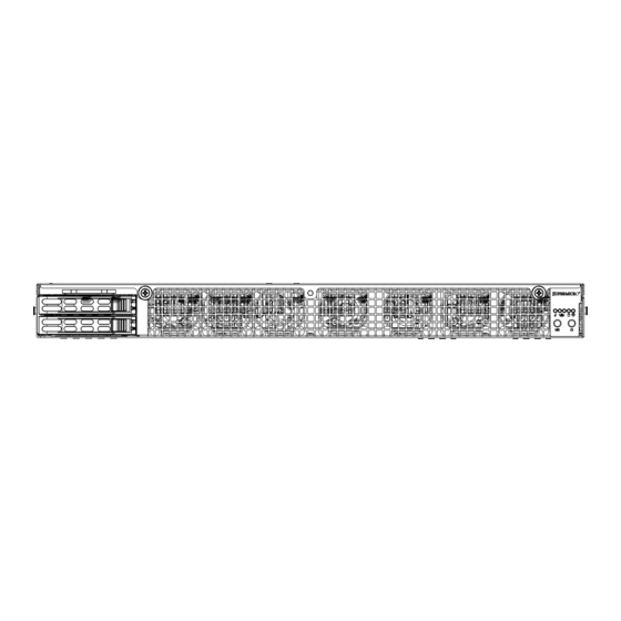
Chapter 3: System Interface Chapter 3 System Interface Overview The server includes a control panel on the front that houses power buttons and status monitoring lights. It also displays status lights on the externally accessible hard drives, and status lights for the power supply visible from the back of the chassis Figure 3-1. -
Page 26: Control Panel Buttons
SuperServer 1028GQ-TXR(T) User's Manual Control Panel Buttons The chassis includes two push-buttons that control power to the system. Power The main power switch is used to apply or remove power from the power supply to the server system. Turning off system power with this button removes the main power but keeps standby power supplied to the system. - Page 27 Chapter 3: System Interface Indicates activity on the hard drive when flashing. Information LED Alerts operator of several states, as noted in the table below. Information LED Status Description An overheat condition has occured. Continuously on and red (This may be caused by cable congestion.) Blinking red (1Hz) Fan failure, check for an inoperative fan.
-
Page 28: Overheating
Some backplanes allow the overheat temperature to be set at 45, 50, or 55 by changing a jumper setting. For more information, consult the backplane user manual at www.supermicro.com. (Click Support, then the Manuals link.) Responses If the server overheats: 1. -
Page 29: Power Supply Leds
Chapter 3: System Interface Power Supply LEDs On the rear of the power supply module, an LED displays the status. • Solid Green: When illuminated, indicates that the power supply is on. • Solid Amber: When illuminated, indicates the power supply is plugged in and turned off, or the system is off but in an abnormal state. - Page 30 SuperServer 1028GQ-TXR(T) User's Manual Notes...
-
Page 31: Chapter 4 Standardized Warning Statements For Ac Systems
Only certified technicians should attempt to install or configure components. Read this chapter in its entirety before installing or configuring components in the Supermicro chassis. Some warnings may not apply for your system. These warnings may also be found on our web site at www.supermicro.com/about/ policies/safety_information.cfm. - Page 32 SUPERSERVER 1028GQ-TXR(T) User's Manual Warnung WICHTIGE SICHERHEITSHINWEISE Dieses Warnsymbol bedeutet Gefahr. Sie befinden sich in einer Situation, die zu Verletzungen führen kann. Machen Sie sich vor der Arbeit mit Geräten mit den Gefahren elektrischer Schaltungen und den üblichen Verfahren zur Vorbeugung vor Unfällen vertraut.
- Page 33 Chapter 4: Warning Statements for AC Systems جسذٌة اصابة ًتتسبب ف حالة ٌوكي أى ًاًك ف خطز ًٌٌع هذا الزهز !تحذٌز الذوائز بالوخاطز الٌاجوة عي ي على علن ، ك هعذات تعول على أي قبل أى الكهزبائٍة حىادث أي وقىع وٌع...
-
Page 34: Installation Instructions
SUPERSERVER 1028GQ-TXR(T) User's Manual Installation Instructions Warning! Read the installation instructions before connecting the system to the power source. 設置手順書 システムを電源に接続する前に、 設置手順書をお読み下さい。 警告 将此系统连接电源前,请先阅读安装说明。 警告 將系統與電源連接前,請先閱讀安裝說明。 Warnung Vor dem Anschließen des Systems an die Stromquelle die Installationsanweisungen lesen. ¡Advertencia! Lea las instrucciones de instalación antes de conectar el sistema a la red de alimentación. -
Page 35: Circuit Breaker
Chapter 4: Warning Statements for AC Systems Circuit Breaker Warning! This product relies on the building's installation for short-circuit (overcurrent) protection. Ensure that the protective device is rated not greater than: 250 V, 20 A. サーキッ ト ・ ブレーカー この製品は、 短絡 (過電流) 保護装置がある建物での設置を前提としています。 保護装置の定格が250 V、... -
Page 36: Power Disconnection Warning
SUPERSERVER 1028GQ-TXR(T) User's Manual 경고! 이 제품은 전원의 단락(과전류)방지에 대해서 전적으로 건물의 관련 설비에 의존합니다. 보호장치의 정격이 반드시 250V(볼트), 20A(암페어)를 초과하지 않도록 해야 합니다. Waarschuwing Dit product is afhankelijk van de kortsluitbeveiliging (overspanning) van uw electrische installatie. Controleer of het beveiligde aparaat niet groter gedimensioneerd is dan 220V, 20A. - Page 37 Chapter 4: Warning Statements for AC Systems ¡Advertencia! El sistema debe ser disconnected de todas las fuentes de energía y del cable eléctrico quitado de los módulos de fuente de alimentación antes de tener acceso el interior del chasis para instalar o para quitar componentes de sistema. Attention Le système doit être débranché...
-
Page 38: Equipment Installation
SUPERSERVER 1028GQ-TXR(T) User's Manual Equipment Installation Warning! Only trained and qualified personnel should be allowed to install, replace, or service this equipment. 機器の設置 トレーニングを受け認定された人だけがこの装置の設置、 交換、 またはサービスを許可 されています。 警告 只有经过培训且具有资格的人员才能进行此设备的安装、更换和维修。 警告 只有經過受訓且具資格人員才可安裝、更換與維修此設備。 Warnung Das Installieren, Ersetzen oder Bedienen dieser Ausrüstung sollte nur geschultem, qualifiziertem Personal gestattet werden. -
Page 39: Restricted Area
Chapter 4: Warning Statements for AC Systems Waarschuwing Deze apparatuur mag alleen worden geïnstalleerd, vervangen of hersteld door geschoold en gekwalificeerd personeel. Restricted Area Warning! This unit is intended for installation in restricted access areas. A restricted access area can be accessed only through the use of a special tool, lock and key, or other means of security. -
Page 40: Battery Handling
SUPERSERVER 1028GQ-TXR(T) User's Manual אזור עם גישה מוגבלת !אזהרה יש להתקין את היחידה באזורים שיש בהם הגבלת גישה. הגישה ניתנת בעזרת .)'כלי אבטחה בלבד (מפתח, מנעול וכד محظورة مناطق ٍنتركُبها ف هذه انىحذة تخصيص تم ،أداة خاصت من خالل استخذاو فقط... - Page 41 Chapter 4: Warning Statements for AC Systems Warnung Bei Einsetzen einer falschen Batterie besteht Explosionsgefahr. Ersetzen Sie die Batterie nur durch den gleichen oder vom Hersteller empfohlenen Batterietyp. Entsorgen Sie die benutzten Batterien nach den Anweisungen des Herstellers. Attention Danger d'explosion si la pile n'est pas remplacée correctement. Ne la remplacer que par une pile de type semblable ou équivalent, recommandée par le fabricant.
-
Page 42: Redundant Power Supplies (If Applicable To Your System)
SUPERSERVER 1028GQ-TXR(T) User's Manual Redundant Power Supplies (if applicable to your system) Warning! This unit might have more than one power supply connection. All connections must be removed to de-energize the unit. 冗長電源装置 このユニッ トは複数の電源装置が接続されている場合があります。 ユニッ トの電源を切るためには、 すべての接続を取り外さなければなりません。 警告 此部件连接的电源可能不止一个,必须将所有电源断开才能停止给该部件供电。 警告... -
Page 43: Backplane Voltage (If Applicable To Your System)
Chapter 4: Warning Statements for AC Systems امداد الطاقة بوحدات عدة اتصاالت جهاز ال يكون لهذا قد الكهرباء عن وحدة ال لعسل كافة االتصاالت يجب إزالة 경고! 이 장치에는 한 개 이상의 전원 공급 단자가 연결되어 있을 수 있습니다. 이 장치에... -
Page 44: Comply With Local And National Electrical Codes
SUPERSERVER 1028GQ-TXR(T) User's Manual מתח בפנל האחורי !הרה אז קיימת סכנת מתח בפנל האחורי בזמן תפעול המערכת. יש להיזהר במהלך .העבודה اللىحة أوالطاقة المىجىدة على التيار الكهزبائي مه خطز هناك هذا الجهاس خدمة كه حذرا عند يعمل النظام عندما يكىن 경고! 시스템이... -
Page 45: Product Disposal
Chapter 4: Warning Statements for AC Systems Attention L'équipement doit être installé conformément aux normes électriques nationales et locales. תיאום חוקי החשמל הארצי !אזהרה הציוד חייבת להיות תואמת לחוקי החשמל המקומיים והארציים התקנת المتعلقة المحلية والىطىية قىاويه يجب أن يمتثل لل الكهربائية... -
Page 46: Hot Swap Fan Warning
SUPERSERVER 1028GQ-TXR(T) User's Manual ¡Advertencia! Al deshacerse por completo de este producto debe seguir todas las leyes y reglamentos nacionales. Attention La mise au rebut ou le recyclage de ce produit sont généralement soumis à des lois et/ou directives de respect de l'environnement. Renseignez-vous auprès de l'organisme compétent. - Page 47 Chapter 4: Warning Statements for AC Systems 警告 危險的可移動性零件。請務必與轉動的風扇葉片保持距離。 當您從機架移除風扇裝 置,風扇可能仍在轉動。小心不要將手指、螺絲起子和其他物品太靠近風扇。 Warnung Gefährlich Bewegende Teile. Von den bewegenden Lüfterblätter fern halten. Die Lüfter drehen sich u. U. noch, wenn die Lüfterbaugruppe aus dem Chassis genommen wird. Halten Sie Finger, Schraubendreher und andere Gegenstände von den Öffnungen des Lüftergehäuses entfernt.
-
Page 48: Power Cable And Ac Adapter
Electrical Appliance and Material Safety Law prohibits the use of UL or CSA -certified cables (that have UL/CSA shown on the code) for any other electrical devices than products designated by Supermicro only. 電源コードとACアダプター 製品を設置する場合、 提供または指定された接続ケーブル、 電源コードとACアダプター... - Page 49 Appareils électroménagers et de loi sur la sécurité Matériel interdit l'utilisation de UL ou CSA câbles certifiés qui ont UL ou CSA indiqué sur le code pour tous les autres appareils électriques que les produits désignés par Supermicro seulement.
- Page 50 SUPERSERVER 1028GQ-TXR(T) User's Manual Notes 4-20...
-
Page 51: Chapter 5 Advanced Motherboard Setup
Chapter 5: Advanced Serverboard Setup Chapter 5 Advanced Motherboard Setup This chapter covers the steps required to install processors and heatsinks to the X10DGQ motherboard, connect the data and power cables and work with the GPU add-on module board. Jumpers and connectors are described and a layout is included in this chapter. -
Page 52: Installing The Processor And Heatsink
• Install the processor into the CPU socket before installing the heatsink. • Refer to the Supermicro web site for updates on CPU support. Installing an LGA 2011 Processor Installing a CPU 1. There are two levers on the LGA 2011 socket. - Page 53 Chapter 5: Advanced Serverboard Setup 3. W ith the sec ond lever f ully Open the load plate. retracted, gently push down on the "Open 1st" lever to loosen the load plate. Lift the load plate with your fingers to open it completely. 4.
- Page 54 UPER ERVER 1028GQ-TXR(T) User's Manual Gently close the load plate. 7. With the "Close 1st" lever fully retracted, gently close the load plate. Push down and lock the lever labeled "Close 1st". 8. Make sure the locking mechanism on the "Close 1st" lever catches the lip of the load plate.
-
Page 55: Installing A Cpu Heatsink
Chapter 5: Advanced Serverboard Setup Installing a CPU Heatsink Installing a Heatsink 1. Place the heatsink on top of the CPU so that the four mounting holes are aligned with those on the retention mechanism. 2. Screw in two diagonal screws (#1 and #2) until just snug—do not over-tighten and damage the CPU. -
Page 56: Connecting Cables
UPER ERVER 1028GQ-TXR(T) User's Manual Connecting Cables Now that the processors are installed, the next step is to connect the cables to the motherboard. These include the data (ribbon) cables for the peripherals and control panel and the power cables. Connecting Data Cables The cables used to transfer data from the peripheral devices have been carefully routed in preconfigured systems to prevent them from blocking the flow of cooling... -
Page 57: Input/Output Ports
Chapter 5: Advanced Serverboard Setup Input/Output Ports The rear panel I/O ports are connected to the motherboard by means of the add- on module. Figure 5-2. Rear Panel I/O Ports Rear Panel I/O Ports 1. USB 3.0 Port 2. USB 3.0 Port 3. -
Page 58: Installing Memory
For best performance, install memory modules of the same type and same speed in the slots as indicated in the tables on the following page. Note: Check the Supermicro web site for recommended memory modules. CAUTION Exercise extreme care when installing or removing DIMM modules to prevent any possible damage. -
Page 59: Memory Support
The server features 16 DIMM slots that can support Load Reduction (LRDIMM) or Registered (RDIMM)/Non-volatile (NV-DIMM) ECC DDR4-2400/2133/1866/1600 MHz memory. Memory speed support depends on the processors installed in the system. For the latest memory updates, refer to the Supermicro website at www. supermicro.com/products/motherboard. - Page 60 UPER ERVER 1028GQ-TXR(T) User's Manual Populating RDIMM/LRDIMM DDR4 Memory Modules Speed (MT/s); Voltage (V); Slots per Channel (SPC) and DIMMs per Channel (DPC) Ranks DIMM Capacity 2 Slots per Channel Per DIMM (GB) Type 1 DPC 2 DPC and Data Width E5-2600 V3 E5-2600 V4...
-
Page 61: Motherboard Details
Chapter 5: Advanced Serverboard Setup Motherboard Details BIOS JSLOT6 JPME2 BIOS LICENSE JBT1 JPW1 JPW2 JPW4 JPW5 X10DGQ Rev. 1.00 CPU2 CPU1 FAN_PWR1 JPW3 IPMI CODE BATTERY BAR CODE JITP1 FAN5 JPW6 Figure 5-4. X10DGQ Layout Notes • " " indicates the location of "Pin 1". •... -
Page 62: Motherboard Quick Reference
Proprietary 50-pin power connectors 1/2 JSTBY1 Standby power header SATA1-6 SATA connectors 1-6 supported by Intel PCH (SATA5/6: support Supermicro SuperDOM with power pins built-in) (CPU1) Slot3/4 PCI-E 3.0 x16 slots 3/4 (CPU2) Slot1/2 PCI-E 3.0 x16 slots 1/2 (CPU0/1) Slot5 PCI-E 3.0 x8/x8 slot 5... -
Page 63: Connector Definitions
Chapter 5: Advanced Serverboard Setup Connector Definitions Power Connectors Two 50-pin proprietary power connectors (JPW1/JPW2) are used to provide main power to your system. Four 8-pin power connectors, located at JPW3/JPW4/ JPW5/JPW6, provide power to GPUs. In addition, two 4-pin power connectors (HDD_PWR1/HDD_PWR2) are used for onboard HDDs, while another 4-pin power connector (FAN_PWR1) powers the fan board AOM-QG-FAN. - Page 64 UPER ERVER 1028GQ-TXR(T) User's Manual NMI Button NMI Button Pin Definitions (JF1) The non-maskable interrupt button Pin# Definition header is located on pins 19 and 20 Control of JF1. Refer to the table on the right Ground for pin definitions. Power LED Power LED Pin Definitions (JF1)
- Page 65 Chapter 5: Advanced Serverboard Setup Overheat (OH)/Fan Fail/PWR Fail/ OH/Fan Fail/ PWR Fail/Blue_ UID LED UID LED Pin Definitions (JF1) Pin# Definition Connect an LED cable to pins 7 and 8 of Front Control Panel to use the Blue_UID LED Overheat/Fan Fail/Power Fail and OH/Fan Fail/Power Fail UID LED connections.
-
Page 66: Other Connectors
JSD1 and JSD2. These Ground connectors are used with Supermciro Ground SuperDOMs to provide backward- compatible power support to non- Supermicro SATADOMs that require external power supply. TPM Header/Port 80 TPM/Port 80 Header Pin Definitions A Trusted Platform Module/Port 80... - Page 67 Chapter 5: Advanced Serverboard Setup Standby Power Header Standby PWR Pin Definitions The onboard standby power header Pin# Definition i s l o c a t e d a t J S T B Y 1 o n t h e +5V Standby motherboard.
- Page 68 UPER ERVER 1028GQ-TXR(T) User's Manual SIO Slot JSLOT6 is the slot for the rear I/O add-on module. PCI Slot • Two PCIe 3.0 x16 slots connected to PLX by four OCuLink cable • One PCIe 3.0 x16 slot and one PCIe x8 slot from CPU1 5-18...
-
Page 69: Jumper Settings
Chapter 5: Advanced Serverboard Setup Jumper Settings Explanation of Jumpers To modify the operation of the motherboard, jumpers can be used Connector to choose between optional settings. Pins Jumpers create shorts between two pins to change the function of the Jumper connector. - Page 70 UPER ERVER 1028GQ-TXR(T) User's Manual VGA Enable/Disable VGA Enable/Disable Jumper Settings JPG1 allows you to enable or disable Jumper Setting Definition the onboard VGA port. The default Pins 1-2 Enabled position is on pins 1 and 2 to enable Pins 2-3 Disabled VGA.
-
Page 71: Onboard Indicators
Chapter 5: Advanced Serverboard Setup Onboard Indicators LAN 1/2 LAN1/2 Port LEDs Link LED Activity LED The Ethernet ports on the rear I/O panel have two indicators. On each LAN Link Indicator port, the LED on the right indicates LED Settings activity by blinking amber. -
Page 72: 5-10 Sata Ports
5-10 SATA Ports Six Serial ATA ports (SATA1-SATA6), supported by the Intel PCH, are located on the motherboard. SATA5/6, colored in yellow, are used with Supermicro SuperDOM (Disk-on-Module) connectors with power pins built in. Supermicro SuperDOM connectors are backward-compatible with regular SATA HDDs and SATA DOMs that require power cables. -
Page 73: Gpu Mounting Board (Aom-Sxm2)
Chapter 5: Advanced Serverboard Setup 5-11 GPU Mounting Board (AOM-SXM2) The system supports four PASCAL SXM2 P100 GPUs installed on the AOM-SXM2 add-on module. It is connected to the motherboard by two bridges and four power cables. It can be connected to network expansion cards using up to four OCuLink cables. -
Page 74: 5-12 Installing Software
UPER ERVER 1028GQ-TXR(T) User's Manual 5-12 Installing Software The Supermicro ftp site contains drivers and utilities for your system at ftp://ftp. supermicro.com. Some of these must be installed, such as the chipset driver. After accessing the ftp site, go into the CDR_Images directory and locate the ISO file for your motherboard. -
Page 75: Superdoctor ® 5
Chapter 5: Advanced Serverboard Setup SuperDoctor ® The Supermicro SuperDoctor 5 is a hardware and operating system services monitoring program that functions in a command-line or web-based interface in Windows and Linux operating systems. The program monitors system health information such as CPU temperature, system voltages, system power consumption, fan speed, and provides alerts via email or Simple Network Management Protocol (SNMP). -
Page 76: 5-13 Onboard Battery
Figure 5-9. SuperDoctor 5 Interface Display Screen (Remote Control) Note: The SuperDoctor 5 program and User’s Manual can be downloaded from the Supermicro web site at http://www.supermicro.com/products/nfo/sms_sd5.cfm. For Linux, we recommend that you use the SuperDoctor II application instead. 5-13 Onboard Battery Please handle used batteries carefully. -
Page 77: Chapter 6 Advanced Chassis Setup
Chapter 6: Advanced Chassis Setup Chapter 6 Advanced Chassis Setup This chapter covers the steps required to install components and perform maintenance on the SC118GQP-R2K05P chassis. The only tool required is a Phillips screwdriver. Review the warnings and precautions before setting up or servicing components. These include information in Chapter 4: Warning Statements for AC Systems. -
Page 78: Static-Sensitive Devices
UPER ERVER 1028GQ-TXR(T) User's Manual Static-Sensitive Devices Electrostatic Discharge (ESD) can damage electronic com ponents. To prevent damage to any printed circuit boards (PCBs), it is important to handle them very carefully. The following measures are generally sufficient to protect your equipment from ESD damage. -
Page 79: Removing The Chassis Cover
Chapter 6: Advanced Chassis Setup Removing the Chassis Cover The SC118GQP has a two piece cover. For either the front cover or the rear cover: R E V I S I O N S DESCRIPTION LOCATION DRAWN 1. Unscrew the two thumb screws on the end of the chassis. 2. -
Page 80: Control Panel
Figure 6-4. Drive Bays RANGETOLERANCE X.xx TITLE: SXM_GPU_SYSTEM_ASSY SIZE: PART NO. Note: Enterprise level hard disk drives are recommended for use in Supermicro 0.200 SCALE : SHEET THE 3RD PROJECTION DWG NO. REV. chassis and servers. For information on recommended HDDs, visit the Supermicro Web site at http://www.supermicro.com/products/nfo/files/storage/SAS-CompList. -
Page 81: Externally Accessable Drives
Chapter 6: Advanced Chassis Setup Externally Accessable Drives The two hot-swap drives are mounted in drive carriers to simplify their installation and removal from the chassis. System power may remain on when removing carriers with drives installed. These carriers also help promote proper airflow for the drive bays. - Page 82 UPER ERVER 1028GQ-TXR(T) User's Manual Dummy Drive Drive Carrier Figure 6-6. Removing a Dummy Drive from Carrier Installing a Drive 1. Remove the dummy drive from the carrier by removing four screws. 2. Install a new drive into the carrier with the printed circuit board side facing down so that the mounting holes in the drive align with those in the carrier.
-
Page 83: Internal Drives
Chapter 6: Advanced Chassis Setup 3. Secure the hard drive into the carrier with the screws. 4. Open the drive carrier handle and use it push the carrier assembly into the chassis. 5. Gently close the drive carrier handle to secure the drive and carrier into the chassis drive bay. -
Page 84: Graphic Processor Units
UPER ERVER 1028GQ-TXR(T) User's Manual Graphic Processor Units The system supports four PASCAL SXM2 P100 GPUs installed on the AOM-SXM2 add-on module in the front of the chassis behind the fans. The GPU positions are identified in the operating system as numbers 1 to 4, left to right side of the chassis (viewed from the chassis front). - Page 85 Chapter 6: Advanced Chassis Setup 4. Install the GPU heatsink. Orient it with the smooth air channel on the chassis right side (when viewed from the front). That is the same side as the power supply modules. The arrow on the heatsink should point to the front of the chassis.
-
Page 86: Adding Expansion Cards
Caution: If you use expansion cards with solid brackets (no venting holes), it is recommended that you populate at most two slots with solid brackets to allow adequate cooling. Please consult Supermicro Tech Support if you plan to populate more than two expansion card slots with solid brackets. - Page 87 Chapter 6: Advanced Chassis Setup Figure 6-12. PCI Expansion Cards (two in chassis left side) RANGETOLERANCE X.xx TITLE: SXM_GPU_SYSTEM_ASSY SIZE: PART NO. 0.200 SCALE : SHEET THE 3RD PROJECTION DWG NO. REV. 6-11...
-
Page 88: Cooling
UPER ERVER 1028GQ-TXR(T) User's Manual Cooling System Fans The chassis contains seven 4-cm counter-rotating, high-performance fans. Fan speed is controlled by system temperature via IPMI. If a fan fails, the remaining fan will ramp up to full speed and the overheat/fan fail LED on the control panel will turn on. -
Page 89: Air Shroud And Block
Chapter 6: Advanced Chassis Setup Air Shroud and Block Cooling is also improved by means of an air block and an air shroud to channel the air flow. The mylar shroud covers the CPUs and memory. Air Block Figure 6-14. Air Block 6-13... -
Page 90: Power Supply
The Power Fail LED will illuminate and remain on until the failed unit has been replaced. Replacement units can be ordered directly from Supermicro. Replace the failed hot-swap unit with another identical power supply unit. The power supply modules can replaced without powering down the system. -
Page 91: Chapter 7 Bios
AMI BIOS setup utility. This setup utility can be accessed by pressing <Delete> at the appropriate time during system boot. Note: For AMI UEFI BIOS Recovery, please refer to the UEFI BIOS Recovery User Guide posted @ http://www.supermicro.com/support/manuals/. -
Page 92: Starting The Setup Utility
SuperServer 1028GQ-TXR(T) User’s Manual Starting the Setup Utility Normally, the only visible Power-On Self-Test (POST) routine is the memory test. As the memory is being tested, press the <Delete> key to enter the main menu of the AMI BIOS setup utility. From the main menu, you can access the other setup screens. - Page 93 The date must be entered in Day MM/DD/YYYY format. The time is entered in HH:MM:SS format. (Note: The time is in the 24-hour format. For example, 5:30 P.M. appears as 17:30:00.). Supermicro X10DGQ BIOS Version This item displays the SMC version of the BIOS ROM used in this system.
-
Page 94: Advanced Setup Configurations
SuperServer 1028GQ-TXR(T) User’s Manual Advanced Setup Configurations Use the arrow keys to select the Advanced tab and press <Enter> to access the submenu items. Caution: Take caution when changing the Advanced settings. An incorrect value, a very high DRAM frequency, or an incorrect DRAM timing setting may make the system unstable. - Page 95 Chapter 7: AMI BIOS AddOn ROM Display Mode Use this item to set the display mode for the Option ROM. Select Keep Current to use the current AddOn ROM Display setting. Select Force BIOS to use the Option ROM display set by the system BIOS. The options are Force BIOS and Keep Current.
- Page 96 SuperServer 1028GQ-TXR(T) User’s Manual Restore on AC Power Loss Use this item to set the power state after a power outage. Select Stay Off for the system power to remain off after a power outage. Select Power On to turn on the system power after a power outage.
- Page 97 Chapter 7: AMI BIOS Cores Enabled Use this item to set the number of CPU cores to be enabled in your system. Enter "0" to enable all cores. The default setting is 0. Execute-Disable Bit (Available if supported by the OS & the CPU) Select Enable for Execute Disable Bit Technology support, which will allow the processor to designate areas in the system memory where an application code can execute and where it cannot, thus preventing a worm or a virus from flooding...
- Page 98 SuperServer 1028GQ-TXR(T) User’s Manual X2 APIC (Advanced Programmable Interrupt Controller) Based on Intel's Hyper-Threading architecture, each logical processor (thread) is assigned 256 APIC IDs (APIDs) in 8-bit bandwidth. When this feature is set to Enable, the APIC ID will expand from 8 bits (X2) to 16 bits to provide 512 APIDs to each thread for CPU performance enhancement.
- Page 99 Chapter 7: AMI BIOS Custom or Energy Efficient) Select Enable for the system to operate at turbo mode with reduced power consumption so that your machine can achieve maximum system performance with the maximum power efficiency possible. The options are Enable and Disable.
- Page 100 SuperServer 1028GQ-TXR(T) User’s Manual CPU C6 Report (Available when Power Technology is set to Custom) Select Enable to allow the BIOS to report the CPU C6 state (ACPI C3) to the operating system. During the CPU C6 state, power to all cache is turned off. The options are Disable and Enable.
- Page 101 Chapter 7: AMI BIOS IOU0 (IIO PCIE Port 2) This feature allows the user to set the bus speed between the IOU0 and the PCI-Exp port specified above. The options are x4x4x4x4, x4x4x8, x8x4x4, x8x8, x16, and Auto. IOU1 (IIO PCIE Port 3) This feature allows the user to set the bus speed between the IOU1 and the PCI-Exp port specified above.
- Page 102 SuperServer 1028GQ-TXR(T) User’s Manual PCI-E Port L1 Exit Latency Use this feature to set the length of time required for the port specified by the user to complete the transition from L1 to L0. The default setting is <1uS, 1uS - 2uS, 2uS - 4uS, 4uS - 8uS, 8uS - 16uS, 16uS - 32uS, 32uS - 64uS, and >64uS.
- Page 103 Chapter 7: AMI BIOS PCI-E Port DeEmphasis Use this item to select the De-Emphasis control setting for a PCI-E port specified by the user. The options are -6.0 dB and -3.5 dB. The following items will display: • PCI-E Port Link Status •...
- Page 104 SuperServer 1028GQ-TXR(T) User’s Manual 2, 3; Enable Phase 1 Only; Enable Phase 0, 1 Only; Advanced; and Enable MMM Offset West. Gen3 (Generation 3) Spec (Specifics) Mode Use this item to set the Specifics mode for PCI-E Generation 3 devices. The options are Auto, 0.70 July, 0.70 Sept and 0.71 Sept.
- Page 105 Chapter 7: AMI BIOS IIO1 Configuration IOU2 (IIO PCIe Port 1) This feature allows the user to set the bus speed between the IOU2 and the PCI-Exp port specified above. The options are x4x4, x8, and Auto. IOU0 (IIO PCIE Port 2) This feature allows the user to set the bus speed between the IOU0 and the PCI-Exp port specified above.
- Page 106 SuperServer 1028GQ-TXR(T) User’s Manual Link Speed Use this item to select the link speed for the PCI-E port specified by the user. The options are Auto, GEN1 (2.5 GT/s), GEN2 (5 GT/s), and GEN3 (8 GT/s). PCI-E Port DeEmphasis Use this item to select the De-Emphasis control setting for a PCI-E port specified by the user.
- Page 107 Chapter 7: AMI BIOS Gen3 (Generation 3) Eq (Equalization) Mode Use this item to set the "Adaptive Equalization" mode for PCI-E Generation 3 devices. The options are Auto; Enable Phase 0, 1, 2, 3; Disable Phase 0, 1, 2, 3; Enable Phase 1 Only; Enable Phase 0, 1 Only; Advanced; and Enable MMM Offset West.
- Page 108 SuperServer 1028GQ-TXR(T) User’s Manual NTB, and NTB to RP. Hide Port? Select Yes to hide the PCI-E port specified from the OS. The options are No and Yes. IOAT Configuration Enable IOAT Select Enable to enable Intel I/OAT (I/O Acceleration Technology), which significantly reduces CPU overhead by leveraging CPU architectural improvements and freeing the system resource for other tasks.
- Page 109 Chapter 7: AMI BIOS QPI (Quick Path Interconnect) Configuration QPI Status The following information will display: • Number of CPU • Number of IIO • Current QPI LInk Speed • Current QPI Link Frequency • QPI Global MMIO Low Base/Limit •...
- Page 110 SuperServer 1028GQ-TXR(T) User’s Manual Memory Frequency Use this item to set the maximum memory frequency for onboard memory modules. The options are Auto, 1333, 1400, 1600, 1800, 1867, 2000, 2133, 2200, 2400, 2600, 2667, 2800, 2993, 3000, 3200, and Reserved. Data Scrambling Select Enabled to enable data scrambling to enhance system performance and data integrity.
- Page 111 Chapter 7: AMI BIOS RAS Mode When Disable is selected, RAS is not supported. When Mirror is selected, the motherboard maintains two identical copies of all data in memory for data backup. When Lockstep is selected, the motherboard uses two areas of memory to run the same set of operations in parallel to boost performance.
- Page 112 SuperServer 1028GQ-TXR(T) User’s Manual USB Configuration • USB Module Version • USB Devices Legacy USB Support Select Enabled to support onboard legacy USB devices. Select Auto to disable legacy support if there are no legacy USB devices present. Select Disable to have all USB devices available for EFI applications only.
- Page 113 Chapter 7: AMI BIOS Configure SATA as Select IDE to configure a SATA drive specified by the user as an IDE drive. Select AHCI to configure a SATA drive specified by the user as an AHCI drive. Select RAID to configure a SATA drive specified by the user as a RAID drive. The options are IDE, AHCI, and RAID.
- Page 114 SuperServer 1028GQ-TXR(T) User’s Manual Serial ATA Port 0-Port 5 This item indicates that a SATA port specified by the user is installed (present) or not. SATA Port 0-Port 5 SATA Device Type (Available when a SATA port is detected) Use this item to specify if the SATA port specified by the user should be connected to a Solid State drive or a Hard Disk Drive.
- Page 115 Chapter 7: AMI BIOS Serial ATA Port 0Port 5 Hot Plug Select Enabled to enable hot-plugging support for a port specified by the user, which will allow the user to replace a SATA disk drive installed on this port without shutting down the system.
- Page 116 SuperServer 1028GQ-TXR(T) User’s Manual • Software Preserve Support sSATA Port 0-Port 3 Select Enabled to enable an sSATA port specified by the user. The options are Disabled and Enabled. sSATA Port 0-Port 3 Hot Plug Select Enabled to enable hot-plugging support for a port specified by the user, which will allow the user to replace a sSATA disk drive installed on this port without shutting down the system.
- Page 117 Chapter 7: AMI BIOS sSATA RAID Option ROM/UEFI Driver Select EFI to load the EFI driver for system boot. Select Legacy to load a legacy driver for system boot. The options are Legacy, EFI, and Disabled. SATA/sSATA RAID Boot Select Select SATA Controller to use a device supported by the SATA connector for system boot.
- Page 118 SuperServer 1028GQ-TXR(T) User’s Manual • ME Firmware Features • ME Firmware Status #1 • ME Firmware Status #2 • Current State • Error Code Altitude This feature indicates the altitude of the platform this machine is located above the sea level. The value is shown in meters. If the value is unknown, enter the number "80000000."...
- Page 119 Chapter 7: AMI BIOS SR-IOV (Available if the system supports Single-Root Virtualization) Select Enabled for Single-Root IO Virtualization support. The options are Disabled and Enabled. Maximum Payload Select Auto for the system BIOS to automatically set the maximum payload value for a PCI-E device to enhance system performance.
- Page 120 SuperServer 1028GQ-TXR(T) User’s Manual Onboard Video Option ROM Use this option to select the type of device installed in the onboard video device used for system boot. The options are Disabled, Legacy, and EFI. VGA Priority Use this item to select the graphics device to be used as the primary video display for system boot.
- Page 121 Chapter 7: AMI BIOS The options for Serial Port 2 are Auto, (IO=2F8h; IRQ=3), (IO=3F8h; IRQ=3, 4, 5, 6, 7, 9, 10, 11, 12), (IO=2F8h; IRQ=3, 4, 5, 6, 7, 9, 10, 11, 12); (IO=3E8h; IRQ=3, 4, 5, 6, 7, 9, 10, 11, 12), and (IO=2E8h; IRQ=3, 4, 5, 6, 7, 9, 10, 11, 12). Device Mode Use this feature to configure SUART clock source settings.
- Page 122 SuperServer 1028GQ-TXR(T) User’s Manual Parity A parity bit can be sent along with regular data bits to detect data transmission errors. Select Even if the parity bit is set to 0, and the number of 1's in data bits is even. Select Odd if the parity bit is set to 0, and the number of 1's in data bits is odd.
- Page 123 Chapter 7: AMI BIOS Redirection After BIOS Post Use this item to enable or disable legacy Console Redirection after BIOS POST. When the option-Bootloader is selected, legacy Console Redirection is disabled before booting the OS. When Always Enable is selected, legacy Console Redirection remains enabled upon OS bootup.
- Page 124 SuperServer 1028GQ-TXR(T) User’s Manual is even. Select Odd if the parity bit is set to 0, and the number of 1's in data bits is odd. Select None if you do not want to send a parity bit with your data bits in transmission.
- Page 125 Chapter 7: AMI BIOS set to Always Enable, legacy Console Redirection remains enabled upon OS boot. The options are Always Enable and Bootloader. Legacy Console Redirection Legacy Console Redirection Settings Legacy Serial Redirection Port Use this feature to select the redirection of legacy OS or OPROM messages. The options are COM1 Console Redirection and COM2/SOL Console Redirection.
- Page 126 SuperServer 1028GQ-TXR(T) User’s Manual Bits Per Second This item sets the transmission speed for a serial port used in Console Redirection. Make sure that the same speed is used in both host computer and the client computer. A lower transmission speed may be required for long and busy lines.
- Page 127 Chapter 7: AMI BIOS Trusted Computing (Available when a TPM device is installed) Configuration Security Device Support If this feature and the TPM jumper on the motherboard are both set to Enabled, onboard security devices will be enabled for TPM (Trusted Platform Module) support to enhance data integrity and network security.
-
Page 128: Event Logs
SuperServer 1028GQ-TXR(T) User’s Manual Event Logs Use this tab page to configure Event Log settings. Change Smbios Event Log Settings Enabling/Disabling Options SMBIOS Event Log Select Enabled to enable SMBIOS (System Management BIOS) Event Logging during system boot. The options are Disabled and Enabled. Runtime Error Logging Support Select Enabled to support Runtime Error Logging. - Page 129 Chapter 7: AMI BIOS When Log is Full Select Erase Immediately to immediately erase all errors in the SMBIOS event log when the event log is full. Select Do Nothing for the system to do nothing when the SMBIOS event log is full. The options are Do Nothing and Erase Immediately. SMBIOS Event Log Standard Settings Log System Boot Event Select Enabled to log system boot events.
-
Page 130: Ipmi
SuperServer 1028GQ-TXR(T) User’s Manual IPMI Select this tab to configure Intelligent Platform Management Interface (IPMI) settings. IPMI Firmware Revision This item indicates the IPMI firmware revision used in your system. Status of BMC (Baseboard Management Controller) This item indicates the status of the BMC installed in your system. System Event Log ... - Page 131 Chapter 7: AMI BIOS Erasing Settings Erase SEL Select Yes, On next reset to erase all system event logs upon next system reboot. Select Yes, On every reset to erase all system event logs upon each system reboot. Select No to keep all system event logs after each system reboot. The options are No;...
- Page 132 SuperServer 1028GQ-TXR(T) User’s Manual Subnet Mask This item displays the sub-network that this computer belongs to. The value of each three-digit number is separated by dots and it should not exceed 255. Station MAC Address This item displays the Station MAC address for this computer. Mac addresses are 6 two-digit hexadecimal numbers.
-
Page 133: Security
Chapter 7: AMI BIOS Security Select this tab to configure security settings. Administrator Password Use this feature to set the administrator password which is required before the user entering the BIOS setup utility. The length of the password should be from 3 characters to 20 characters long. - Page 134 SuperServer 1028GQ-TXR(T) User’s Manual Secure Boot Select Enable for secure boot support to ensure system security at bootup. The options are Disabled and Enabled. Secure Boot Mode This item allows the user to select the desired secure boot mode for the system. The options are Standard and Custom.
- Page 135 Chapter 7: AMI BIOS Delete KEK (Key Exchange Key) Select <Yes> to confirm deletion of the KEK from the NVRAM (Non-Volatile RAM). Set New KEK (Key Exchange Key) Select <Yes> to confirm that a new KEK will be set in the NVRAM (Non-Volatile RAM).
- Page 136 SuperServer 1028GQ-TXR(T) User’s Manual Set New DBT (DataBase Timer) Select <Yes> to confirm that the new database timer will be set in the NVRAM (Non-Volatile RAM). Append DBT (DataBase Timer) Select <Yes> to load the new database timer from the manufacturer defaults. Select <No>...
-
Page 137: Boot
Chapter 7: AMI BIOS Boot Select this tab to configure boot settings. Boot Configuration Boot Mode Select Use this item to select the type of device to be used for system boot. The options are Legacy, UEFI, and Dual. Fixed Boot Order Priorities This option prioritizes the order of bootable devices from which the system will boot. - Page 138 SuperServer 1028GQ-TXR(T) User’s Manual • Boot Option #8 • Boot Option #9 • Boot Option #10 • Boot Option #11 • Boot Option #12 • Boot Option #13 • Boot Option #14 • Boot Option #15 Delete Boot Option Use this item to select a boot device to delete from the boot priority list.
-
Page 139: Save & Exit
Chapter 7: AMI BIOS Save & Exit Select this tab to configure settings for saving and exiting. Discard Changes and Exit Select this option and press <Enter> to quit the BIOS setup without making any permanent changes to the system configuration, and reboot the computer. Save Changes and Reset When you have completed the system configuration changes, select this option and press <Enter>... - Page 140 SuperServer 1028GQ-TXR(T) User’s Manual Restore Optimized Defaults To set this feature, select this option and press <Enter> to reload the manufacturer default settings that are designed for maximum system performance but not for maximum stability. Save as User Defaults To set this feature, select this option and press <Enter> to save current default settings for future use.
-
Page 141: Appendix A Bios Error Beep Codes
Appendix A: BIOS Error Beep Codes Appendix A BIOS Error Beep Codes During the POST (Power-On Self-Test) routines, which are performed at each system boot, errors may occur. Non-fatal errors are those which, in most cases, allow the system to continue to boot. - Page 142 UPER ERVER 1028GQ-TXR(T) User's Manual Notes...
-
Page 143: Appendix B System Specifications
Memory Capacity Sixteen DIMM slots supporting up to 512 GB of LRDIMM. 1 TB of RDIMM ECC DDR4-2400/2133/1866/1600MHz memory. Note: Refer to Section 5-5 for details on installation. Check the Supermicro website (www. supermicro.com) for the latest memory support information. - Page 144 SUPERSERVER 1028GQ-TXR(T) USER'S MANUAL Chassis SC118GQP-R2K05P for (1U rackmount) Dimensions: (WxHxD) 17.2 x 1.7 x 35.2 in. (437 x 43 x 894 mm) Weight Net Weight: 45 lbs (15.9 kg) Gross Weight: 58 lbs (21.8 kg) System Cooling Seven 4-cm fans, one air shroud, two passive CPU heat sinks, four passive GPU heatsinks System Input Requirements AC Input Voltage: 100-240Vac auto-range...
- Page 145 Appendix B: System Specifications Regulatory Compliance Electromagnetic Emissions: FCC part 15 subpart B Class A, EN 55032 Class A, EN 61000-3-2/-3-3, CISPR 32 Class A, VCCI V-3, AS-NZS CISPR 32 Electromagnetic Immunity: EN 55024/CISPR 24, (EN 61000-4-2, EN 61000-4-3, EN 61000-4-4, EN 61000-4-5, EN 61000-4-6, EN 61000-4-8, EN 61000-4-11) Safety: CSA/EN/IEC/UL 60950-1 Compliant, UL or CSA Listed (USA and Canada), CE Marking (Europe) California Best Management Practices Regulations for Perchlorate Materials:...
- Page 146 SUPERSERVER 1028GQ-TXR(T) USER'S MANUAL (continued from front) The products sold by Supermicro are not intended for and will not be used in life support systems, medical equipment, nuclear facilities or systems, aircraft, aircraft devices, aircraft/emergency communication devices or other critical systems whose failure to perform be reasonably expected to result in significant injury or loss of life or catastrophic property damage.
Need help?
Do you have a question about the SUPERSERVER 1028GQ-TXRT and is the answer not in the manual?
Questions and answers