Table of Contents
Advertisement
Quick Links
Advertisement
Table of Contents

Related Manuals for Supermicro SUPERSERVER 1028R-MCT


Summary of Contents for Supermicro SUPERSERVER 1028R-MCT
- Page 1 UPER ERVER 1028R-MCT 1028R-MCTR USER’S MANUAL 1.0a...
- Page 2 This manual is written for professional system integrators and PC technicians. It pro- mentation, is the property of Supermicro and/or its licensors, and is supplied only under a license. Any use or reproduction of this product is not allowed, except as expressly permitted by the terms vides information for the installation and use of the SuperServer 1028R-MCT/MCTR.
- Page 3 Preface UPER ERVER 1028R-MCT/MCTR User's Manual Notes Chapter 5: Advanced Serverboard Setup Chapter 5 provides detailed information on the X10DRL-CT serverboard, including the locations and functions of connections, headers and jumpers. Refer to this chapter when adding or removing processors or main memory and when reconfig- uring the serverboard.
-
Page 4: Table Of Contents
Circuit Breaker ....................4-5 Control Panel ....................1-3 Power Disconnection Warning ................ 4-6 Cooling System ....................1-3 Equipment Installation ..................4-8 Contacting Supermicro ..................1-5 Restricted Area ....................4-9 Chapter 2 Server Installation Battery Handling .................... 4-10 Overview ......................2-1 Redundant Power Supplies ................ - Page 5 UPER ERVER 1028R-MCT/MCTR User's Manual Connector Definitions ................... 5-13 Jumper Settings .................... 5-20 5-10 Onboard Indicators ..................5-23 5-11 SAS/SATA Ports .................... 5-24 5-12 Installing Software ..................5-25 SuperDoctor® 5 .................... 5-26 5-13 Onboard Battery .................... 5-27 Chapter 6 Advanced Chassis Setup Static-Sensitive Devices ..................
-
Page 6: Overview
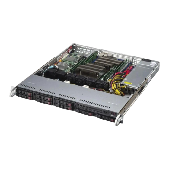
Chapter 1 Introduction Overview The SuperServer 1028R-MCT/MCTR is a high-end server comprised of two main subsystems: the SC113MFAC2-605CB/SC113MFAC2-R606CB 1U server chassis and the X10DRL-CT dual processor serverboard. Please refer to our website for information on operating systems that have been certified for use with the system (www.supermicro.com). -
Page 7: Serverboard Features
ERVER 1028R-MCT/MCTR User's Manual Serverboard Features Server Chassis Features At the heart of the SuperServer 1028R-MCT/MCTR lies the X10DRL-CT, a dual The SC113MFAC2-605CB/SC113MFAC2-R606CB is a short depth (< 20") 1U processor serverboard based on Intel's PCH C612 chipset. Below are the main chassis that features eight 2.5"... -
Page 8: Contacting Supermicro
San Jose, CA 95131 U.S.A. Tel: +1 (408) 503-8000 Fax: +1 (408) 503-8008 VR12.5 VR12.5 #2-4 5 PHASE 5 PHASE #1-4 #2-3 Email: marketing@supermicro.com (General Information) 145W 145W #1-3 #2-2 #1-2 #2-1 9.6G #1-1 support@supermicro.com (Technical Support) SNB CORE SNB CORE DDR-IV... - Page 9 UPER ERVER 1028R-MCT/MCTR User's Manual Notes...
-
Page 10: Chapter 2 Server Installation
Server Installation Overview This chapter provides a quick setup checklist to get your SuperServer 1028R-MCT/ MCTR up and running. Following these steps in the order given should enable you to have the system operational within a minimum amount of time. This quick setup as- sumes that your SuperServer 1028R-MCT/MCTR system has come to you with the processors and memory preinstalled. -
Page 11: Warnings And Precautions
Chapter 2: Server Installation UPER ERVER 1028R-MCT/MCTR User's Manual Rack Mounting Considerations installation only in a Restricted Access Location (dedicated equipment rooms, service closets and the like). Ambient Operating Temperature • This product is not suitable for use with visual display work place devices If installed in a closed or multi-unit rack assembly, the ambient operating tempera- acccording to §2 of the the German Ordinance for Work with Visual Display Units. -
Page 12: Installing The System Into A Rack
Inner Rails The SC113MFAC2 chassis includes a set of inner rails in two sections: inner rails This section provides information on installing the SuperServer 1028R-MCT/MCTR and inner rail extensions. The inner rails are pre-attached and do not interfere with into a rack. Note: The rails will fit a rack between 26" and 33.5" deep. -
Page 13: Outer Rails
Chapter 2: Server Installation UPER ERVER 1028R-MCT/MCTR User's Manual Outer Rails Installing the Outer Rails to the Rack (Figures 2-3 and 2-4) 1. Attach the short bracket to the outside of the long bracket. You must align the pins with the slides. Also, both bracket ends must face the same direction. 2. -
Page 14: Installing The Server Into A Telco Rack
Installing the Chassis into a Rack (Figure 2-5) Installing the Server into a Telco Rack To install the SuperServer 1028R-MCT/MCTR into a Telco type rack, use two L- 1. Confirm that chassis includes the inner rails and rail extensions . Also, confirm shaped brackets on either side of the chassis (four total). - Page 15 UPER ERVER 1028R-MCT/MCTR User's Manual Notes 2-10...
-
Page 16: Overview
Chapter 3: System Interface Chapter 3 System Interface Overview There are several LEDs on the control panel to keep you constantly informed of the overall status of the system as well as the three buttons described below. Control Panel Buttons There are three buttons located on the front of the chassis: a UID button, a reset button and a power on/off button. -
Page 17: Control Panel Leds
Chapter 3: System Interface UPER ERVER 1028R-MCT/MCTR Manual Control Panel LEDs The control panel located on the front of the SC113MFAC2 chassis has five LEDs. These LEDs provide you with critical information related to different parts of the system. This section explains what each LED indicates when illuminated and any Information LED corrective action you may need to take. - Page 18 UPER ERVER 1028R-MCT/MCTR Manual Notes...
-
Page 19: Chapter 4 Standardized Warning Statements For Ac Systems
Only certified technicians should attempt to install or configure components. Read this appendix in its entirety before installing or configuring components in the Supermicro chassis. These warnings may also be found on our web site at http://www.supermicro.com/ about/policies/safety_information.cfm. Warning Definition Warning! This warning symbol means danger. - Page 20 Warning Statements for AC Systems UPER ERVER 1028R-MCT/MCTR User's Manual جسذٌة اصابة ًتتسبب ف حالة ٌوكي أى ًاًك ف خطز ًٌٌع هذا الزهز !تحذٌز Warnung الذوائز بالوخاطز الٌاجوة عي ي على علن ، ك هعذات تعول على أي قبل أى الكهزبائٍة...
-
Page 21: Installation Instructions
Chapter 4: Warning Statements for AC Systems UPER ERVER 1028R-MCT/MCTR User's Manual Installation Instructions Circuit Breaker Warning! Warning! Read the installation instructions before connecting the system to the power source. This product relies on the building's installation for short-circuit (overcurrent) 設置手順書... -
Page 22: Power Disconnection Warning
Chapter 4: Warning Statements for AC Systems UPER ERVER 1028R-MCT/MCTR User's Manual Warnung Das System muss von allen Quellen der Energie und vom Netzanschlusskabel في التي تم تثبيتها مه الدوائرالقصيرة الحمايت معداث يعتمد على هذا المنتج getrennt sein, das von den Spg.Versorgungsteilmodulen entfernt wird, bevor es المبنى... -
Page 23: Equipment Installation
Chapter 4: Warning Statements for AC Systems UPER ERVER 1028R-MCT/MCTR User's Manual Equipment Installation Waarschuwing Deze apparatuur mag alleen worden geïnstalleerd, vervangen of hersteld door geschoold en gekwalificeerd personeel. Warning! Only trained and qualified personnel should be allowed to install, replace, or service Restricted Area this equipment. -
Page 24: Battery Handling
Chapter 4: Warning Statements for AC Systems UPER ERVER 1028R-MCT/MCTR User's Manual Warnung אזור עם גישה מוגבלת Bei Einsetzen einer falschen Batterie besteht Explosionsgefahr. Ersetzen Sie die !אזהרה Batterie nur durch den gleichen oder vom Hersteller empfohlenen Batterietyp. יש להתקין את היחידה באזורים שיש בהם הגבלת גישה. הגישה ניתנת בעזרת Entsorgen Sie die benutzten Batterien nach den Anweisungen des Herstellers. -
Page 25: Redundant Power Supplies
Chapter 4: Warning Statements for AC Systems UPER ERVER 1028R-MCT/MCTR User's Manual Redundant Power Supplies امداد الطاقة بوحدات عدة اتصاالت جهاز ال يكون لهذا قد الكهرباء عن وحدة ال لعسل كافة االتصاالت يجب إزالة Warning! This unit might have more than one power supply connection. All connections must 경고! be removed to de-energize the unit. -
Page 26: Comply With Local And National Electrical Codes
Chapter 4: Warning Statements for AC Systems UPER ERVER 1028R-MCT/MCTR User's Manual Attention ¡Advertencia! Lorsque le système est en fonctionnement, des tensions électriques circulent sur La instalacion del equipo debe cumplir con las normas de electricidad locales y le fond de panier. Prendre des précautions lors de la maintenance. nacionales.Attention L'équipement doit être installé... -
Page 27: Hot Swap Fan Warning
Chapter 4: Warning Statements for AC Systems UPER ERVER 1028R-MCT/MCTR User's Manual 当您从机架移除风扇装置,风扇可能仍在转动。小心不要将手指、螺丝起子和其他 Warnung 物品太靠近风扇 Die Entsorgung dieses Produkts sollte gemäß allen Bestimmungen und Gesetzen des Landes erfolgen. 警告 ¡Advertencia! 當您從機架移除風扇裝置,風扇可能仍在轉動。小心不要將手指、螺絲起子和其他 物品太靠近風扇。 Al deshacerse por completo de este producto debe seguir todas las leyes y reglamentos nacionales. -
Page 28: Power Cable And Ac Adapter
UL ou CSA câbles certifiés qui ont UL ou CSA indiqué sur le code use of UL or CSA -certified cables (that have UL/CSA shown on the code) for any pour tous les autres appareils électriques que les produits désignés par Supermicro other electrical devices than products designated by Supermicro only. - Page 29 Elektrisch apparaat en veiligheidsinformatiebladen wet verbiedt het gebruik van UL of CSA gecertificeerde kabels die UL of CSA die op de code voor andere elektrische apparaten dan de producten die door Supermicro alleen. 4-20...
-
Page 30: Chapter 5 Advanced Serverboard Setup
Chapter 5: Advanced Serverboard Setup Chapter 5 Advanced Serverboard Setup This chapter covers the steps required to install processors and heatsinks to the X10DRL-CT serverboard, connect the data and power cables and install add-on cards. All serverboard jumpers and connections are described and a layout and quick reference chart are included in this chapter. -
Page 31: Processor And Heatsink Installation
Install the processor into the CPU socket before installing the heatsink. "Warning" out of the load plate. IMPORTANT! • Refer to the Supermicro web site for updates on CPU support. 5. Holding the CPU carefully above the socket, orient the CPU so that all keys and edges will fit the socket. -
Page 32: Installing A Cpu Heatsink
Chapter 5: Advanced Serverboard Setup UPER ERVER 1028R-MCT/MCTR User's Manual Installing a CPU Heatsink Gently close the load plate. 1. Remove power from the system and unplug the AC power cord(s) from the 7. With the "Close 1st" lever fully power supply. -
Page 33: Connecting Cables
Chapter 5: Advanced Serverboard Setup UPER ERVER 1028R-MCT/MCTR User's Manual Connecting Cables Figure 5-2. Front Control Panel Header Pins (JF1) Now that the processors are installed, the next step is to connect the cables to the serverboard. These include the data (ribbon) cables for the peripherals and control Ground panel and the power cables. -
Page 34: Installing Memory
ERVER 1028R-MCT/MCTR User's Manual Installing Memory Processor & Memory Module Population Configuration For memory to work properly, follow the tables below for memory installation. Note: Check the Supermicro web site for recommended memory modules. Processors and their Corresponding Memory Modules CAUTION CPU#... -
Page 35: Adding Pci Cards
Chapter 5: Advanced Serverboard Setup UPER ERVER 1028R-MCT/MCTR User's Manual Adding PCI Cards Serverboard Details Figure 5-5. SUPER X10DRL-CT Layout PCI Expansion Slots One riser card is used to support a PCI expansion (add-on) card in the system. JPL1 LEDBMC JUIDB1 The SC113MFAC2 chassis can accommodate one full-height, half-length PCI ex- USB12/13(3.0) -
Page 36: Connector Definitions
Chapter 5: Advanced Serverboard Setup UPER ERVER 1028R-MCT/MCTR User's Manual Connector Definitions Connector Description ATX Power 24-pin Connector Pin Definitions Chassis Intrusion Header Power Connectors Pin# Definition Pin # Definition I-SATA0~5 SATA 3.0 Ports +3.3V +3.3V The 24 - pin main power connector USB 2/3 USB 2.0 Header (J24) is used to provide power to the... - Page 37 Chapter 5: Advanced Serverboard Setup UPER ERVER 1028R-MCT/MCTR User's Manual NIC1/NIC2 (LAN1/LAN2) Power Button The NIC (Network Interface Controller) The Power Button connection is located LAN1/LAN2 LED LED connection for LAN port 1 is located on pins 1 and 2 of JF1. Momentarily Pin Definitions (JF1) Power Button on pins 11 and 12 of JF1, and the LED...
- Page 38 Pin# Definition Connector JNVI2C1 is a management LSI SAS 3108 TFM Connector header for Supermicro AOC NVme PCI-E No Connection The TFM connector is used to attach a TFM module and SuperCap to the peripheral cards. Please connect the I2C serverboard for LSI CacheVault technology support.
- Page 39 The rear UID LED (UID) is located next DOM devices Ground Ground to the UID switch and the front UID LED Note: When using Supermicro Super- Ground I-SGPIO0/1 & S-SGPIO Support is located on pin 7 on JF1. When you DOMs, no external power cabling is re-...
-
Page 40: Jumper Settings
Chapter 5: Advanced Serverboard Setup UPER ERVER 1028R-MCT/MCTR User's Manual Jumper Settings C Bus to PCI-Exp. Slots Explanation of Jumpers Use Jumpers JI C1 and JI C2 to connect C for PCI-E slots the System Management Bus (I C) to on- To modify the operation of the serverboard, Jumper Settings board PCI-Express slots to improve PCI... -
Page 41: 5-10 Onboard Indicators
Chapter 5: Advanced Serverboard Setup UPER ERVER 1028R-MCT/MCTR User's Manual 5-10 Onboard Indicators Gb LAN LED Connection Speed Indication ME Mode Select LED State Definition LAN1/LAN2 LEDs Close pins 2 and 3 of jumper JPME2 to ME Mode Select No connection or 10 Mb/s bypass SPI flash security and force the The Ethernet ports have two LEDs. -
Page 42: 5-11 Sas/Sata Ports
ERVER 1028R-MCT/MCTR User's Manual 5-11 SAS/SATA Ports 5-12 Installing Software The Supermicro FTP site contains drivers and utilities for your system at ftp://ftp. SATA 3.0 and SAS 3.0 Ports supermicro.com. Some of these must be installed, such as the chipset driver. -
Page 43: Superdoctor® 5
SuperDoctor® 5 5-13 Onboard Battery The Supermicro SuperDoctor 5 is a program that functions in a command-line or Please handle used batteries carefully. Do not damage the battery in any way; a web-based interface in Windows and Linux operating systems. The program moni- damaged battery may release hazardous materials into the environment. - Page 44 UPER ERVER 1028R-MCT/MCTR User's Manual Notes 5-28...
-
Page 45: Chapter 6 Advanced Chassis Setup
Chapter 6: Advanced Chassis Setup Chapter 6 Advanced Chassis Setup This chapter covers the steps required to install components and perform mainte- nance on the SC113MFAC2-605B/SC113MFAC2-R605B chassis. For component installation, follow the steps in the order given to eliminate the most common problems encountered. -
Page 46: Control Panel
Chapter 6: Advanced Chassis Setup UPER ERVER 1028R-MCT/MCTR User's Manual Adding a System Fan Figure 6-1. Chassis: Front and Rear Views 1. Turn off the power to the system and unplug the power cord(s). Control Panel 2. Remove the chassis cover then remove the dummy fan from the fan tray. 3. -
Page 47: Drive Bay Installation/Removal
Chapter 6: Advanced Chassis Setup UPER ERVER 1028R-MCT/MCTR User's Manual 2. Align the drive in the carrier so that the screw holes of both line up. Note that there are holes in the carrier marked “SATA” to aid in correct installation. 3. -
Page 48: Dvd Drive Installation
Chapter 6: Advanced Chassis Setup UPER ERVER 1028R-MCT/MCTR User's Manual Figure 6-4. Removing a Hard Drive Figure 6-5. Installing a DVD-ROM Drive DVD Drive Installation The SC113MFAC2 chassis may have a DVD-ROM installed (optional). Installing or Replacing a DVD-ROM Drive (Figure 6-5) 1. -
Page 49: Power Supply
An amber light will be illuminated on the power supply when the power is off. An The SuperServer 1028R-MCT has a single 600 watt power supply while the 1028R- illuminated green light indicates that the power supply is operating. If either of the MCTR features redundant, 600W hot-plug high-efficiency power supplies. - Page 50 UPER ERVER 1028R-MCT/MCTR User's Manual Figure 6-6. Removing/Replacing the Power Supply Single power supply: remove screws Dual: use release tab to remove Note: 1028R-MCT server (single power supply model) is shown above. 6-10...
-
Page 51: Chapter 7 Bios
When an option is selected in the left frame, it is highlighted in white. Often a text message will accompany it. Note: the AMI BIOS has default text messages built in. Supermicro retains the option to include, omit, or change any of these text messages. -
Page 52: How To Start The Setup Utility
Flashing the wrong BIOS can cause irreparable damage to the system. In no event shall as 17:30:00. Supermicro be liable for direct, indirect, special, incidental, or consequential damages arising from a BIOS update. If you have to update the BIOS, do not shut down or reset Supermicro X10DRL-CT the system while the BIOS is updating to avoid possible boot failure. -
Page 53: Advanced Setup Configurations
Chapter 7: BIOS UPER ERVER 1028R-MCT/MCTR User's Manual Advanced Setup Configurations Wait For 'F1' If Error Select Enabled to force the system to wait until the 'F1' key is pressed if an error Use the arrow keys to select Advanced setup and press <Enter> to access the occurs. -
Page 54: Cpu Configuration
Chapter 7: BIOS UPER ERVER 1028R-MCT/MCTR User's Manual CPU Configuration Execute-Disable Bit (Available if supported by the OS & the CPU) Select Enable for Execute Disable Bit Technology support, which will allow the This submenu displays the following CPU information as detected by the BIOS. It processor to designate areas in the system memory where an application code can also allows the user to configure CPU settings. -
Page 55: Advanced Power Management Configuration
Chapter 7: BIOS UPER ERVER 1028R-MCT/MCTR User's Manual P-state Coordination X2APIC (Advanced Programmable Interrupt Controller) This feature is used to change the P-state (Power-Performance State) coordi- Based on Intel's Hyper-Threading architecture, each logical processor (thread) is nation type. P-state is also known as "SpeedStep" for Intel processors. Select assigned 256 APIC IDs (APIDs) in 8-bit bandwidth. -
Page 56: Chipset Configuration
Chapter 7: BIOS UPER ERVER 1028R-MCT/MCTR User's Manual No Snoop Chipset Configuration Select Enable to support no-snoop mode for each CB device. The options are Warning! Please set the correct settings for the items below. A wrong configuration Disable and Enable. setting may cause the system to become malfunction. -
Page 57: Memory Configuration
Chapter 7: BIOS UPER ERVER 1028R-MCT/MCTR User's Manual QPI (Quick Path Interconnect) Configuration Memory Configuration QPI Status Enforce POR The following information will display: Select Enable to enforce POR restrictions on DDR4 frequency and voltage • programming. The options are Enabled and Disabled. Number of CPU Memory Frequency •... -
Page 58: South Bridge Configuration
Chapter 7: BIOS UPER ERVER 1028R-MCT/MCTR User's Manual Memory RAS (Reliability_Availability_Serviceability) South Bridge Configuration Configuration The following South Bridge information will display: Use this submenu to configure the following Memory RAS settings. USB Configuration RAS Mode • When Disable is selected, RAS is not supported. When Mirror is selected, the USB Module Version motherboard maintains two identical copies of all data in memory for data backup. - Page 59 Chapter 7: BIOS UPER ERVER 1028R-MCT/MCTR User's Manual SATA Configuration EHCI2 Select Enabled to enable EHCI (Enhanced Host Controller Interface) support on When this submenu is selected, AMI BIOS automatically detects the presence of USB 2.0 connector #2 (-at least one USB 2.0 connector should be enabled for EHCI the SATA devices that are supported by the Intel PCH chip and displays the fol- support.) The options are Disabled and Enabled.
- Page 60 Chapter 7: BIOS UPER ERVER 1028R-MCT/MCTR User's Manual *If the item above "Configure SATA as" is set to IDE, the following items will Port 0 ~ Port 5 Spin Up Device display: On an edge detect from 0 to 1, set this item to allow the PCH to start a COMRE- SET initialization to the device.
- Page 61 Chapter 7: BIOS UPER ERVER 1028R-MCT/MCTR User's Manual PCIe/PCI/PnP Configuration on the system configuration. Select Disabled to disable ASPM support. The options are Disabled, and Auto. The following PCI information will be displayed: Warning: Enabling ASPM support may cause some PCI-E devices to fail! •...
- Page 62 Chapter 7: BIOS UPER ERVER 1028R-MCT/MCTR User's Manual Super IO Configuration COM1 Console Redirection Settings Super IO Chip AST2400 Terminal Type This feature allows the user to select the target terminal emulation type for Con- Serial Port 1 Configuration / Serial Port 2 Configuration sole Redirection.
- Page 63 Chapter 7: BIOS UPER ERVER 1028R-MCT/MCTR User's Manual Recorder Mode SOL/COM2 Console Redirection Settings Select Enabled to capture the data displayed on a terminal and send it as text Use this feature to specify how the host computer will exchange data with the client messages to a remote server.
- Page 64 Chapter 7: BIOS UPER ERVER 1028R-MCT/MCTR User's Manual the receiving buffer is full. Send a "Start" signal to start data-sending when the Serial Port for Out-of-Band Management/Windows Emergency Management Services (EMS) receiving buffer is empty. The options are None and Hardware RTS/CTS. The submenu allows the user to configure Console Redirection settings to sup- VT-UTF8 Combo Key Support port Out-of-Band Serial Port management.
-
Page 65: Event Logs
Chapter 7: BIOS UPER ERVER 1028R-MCT/MCTR User's Manual Event Logs ACPI Settings Use this feature to configure Event Log settings. WHEA Support Select Enabled to support the Windows Hardware Error Architecture (WHEA) plat- form and provide a common infrastructure for the system to handle hardware errors within the Windows OS environment to reduce system crashes and to enhance system recovery and health monitoring. -
Page 66: Ipmi
Chapter 7: BIOS UPER ERVER 1028R-MCT/MCTR User's Manual Memory Correctable Error Threshold IPMI Use this item to enter the threshold value for correctable memory errors. The default Use this feature to configure Intelligent Platform Management Interface (IPMI) setting is 10. settings. -
Page 67: Security Settings
Chapter 7: BIOS UPER ERVER 1028R-MCT/MCTR User's Manual Security Settings When SEL is Full This feature allows the user to determine what the BIOS should do when the sys- This menu allows the user to configure the following security settings for the tem event log is full. -
Page 68: Boot Settings
Chapter 7: BIOS UPER ERVER 1028R-MCT/MCTR User's Manual • Boot Settings Dual Boot Order #7 • Use this feature to configure Boot Settings: Dual Boot Order #8 • Dual Boot Order #9 • Dual Boot Order #10 • Dual Boot Order #11 •... -
Page 69: Save & Exit
Chapter 7: BIOS UPER ERVER 1028R-MCT/MCTR User's Manual Network Drive BBS Priorities Save & Exit • Legacy Boot Order #1 Select the Save & Exit tab from the BIOS setup screen to configure the settings below. UEFI Application Boot Priorities •... - Page 70 UPER ERVER 1028R-MCT/MCTR User's Manual Restore Defaults To set this feature, select Restore Defaults from the Exit menu and press <Enter>. These are manufacture default settings designed for maximum system performance but not for maximum stability. Save As User Defaults To set this feature, select Save as User Defaults from the Exit menu and press <En- ter>.
-
Page 71: Appendix A Bios Error Beep Codes
Appendix A: BIOS Error Beep Codes Appendix A BIOS Error Beep Codes During the POST (Power-On Self-Test) routines, which are performed at each system boot, errors may occur. Non-fatal errors are those which, in most cases, allow the system to continue to boot. - Page 72 UPER ERVER 1028R-MCT/MCTR User's Manual Notes...
-
Page 73: Appendix B System Specifications
Appendix B: System Specifications Appendix B System Specifications Processors Dual Intel ® Xeon ® E5-2600 v3/v4 Series processors in R3 LGA 2011 sockets Note: Please refer to our web site for a complete listing of supported processors. Chipset Intel PCH 612 BIOS 128 Mb SPI AMI®... - Page 74 Rated Output Voltages: +12V (50A), +5Vsb (3A) Disclaimer (continued from front) The products sold by Supermicro are not intended for and will not be used in life support systems, medical equipment, nuclear facilities or systems, aircraft, aircraft devices, aircraft/emergency com- munication devices or other critical systems whose failure to perform be reasonably expected to result in significant injury or loss of life or catastrophic property damage.
- Page 75 UPER ERVER 1028R-MCT/MCTR User's Manual Notes...
Need help?
Do you have a question about the SUPERSERVER 1028R-MCT and is the answer not in the manual?
Questions and answers