Table of Contents
Advertisement
Quick Links
Advertisement
Table of Contents

Related Manuals for Supermicro SUPERSERVER 1028UX-TR4


Summary of Contents for Supermicro SUPERSERVER 1028UX-TR4
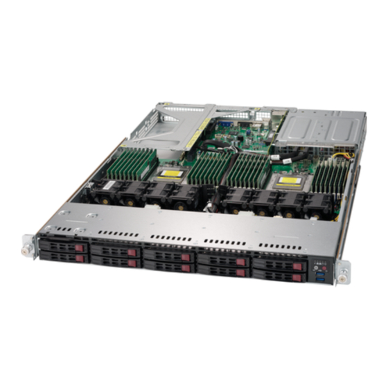
- Page 1 SUPERSERVER ® 1028UX-TR4 User's Manual Revision 1.0a...
- Page 2 This product, including software and documentation, is the property of Supermicro and/or its licensors, and is supplied only under a license. Any use or reproduction of this product is not allowed, except as expressly permitted by the terms of said license.
- Page 3 About This Manual This manual is written for professional system integrators and PC technicians. It provides information for the installation and use of the SuperServer 1028UX-TR4. Installation and maintenance should be performed by experienced technicians only. The SuperServer 1028UX-TR4 is a high-end server based on the SC119UAC2-R750 1U rackmount chassis and the dual processor X10DRU-X serverboard.
- Page 4 SUPERSERVER 1028UX-TR4 User's Manual Chapter 6: Advanced Chassis Setup Refer to Chapter 6 for detailed information on the SC119UAC2-R750 server chassis. You should follow the procedures given in this chapter when installing, removing or reconfiguring hardl drives and when replacing system power supply units and cooling fans.
- Page 5 SUPERSERVER 1028UX-TR4 User's Manual Notes...
-
Page 6: Table Of Contents
System Power ....................1-3 Hard Drives ..................... 1-3 PCI Expansion Slots ..................1-3 Front Control Panel ..................1-3 Cooling System ....................1-3 Contacting Supermicro ..................1-5 Chapter 2 Server Installation Overview ......................2-1 Unpacking the System ..................2-1 Preparing for Setup ..................2-1 Choosing a Setup Location ................ - Page 7 Table of Contents Control Panel Buttons ..................3-2 Control Panel LEDs ..................3-2 Overheating ..................... 3-3 Drive Carrier LEDs ..................3-4 Power Supply LEDs ..................3-4 Chapter 4 Standardized Warning Statements for AC Systems About Standardized Warning Statements ............4-1 Warning Definition ...................
- Page 8 UPER ERVER 1028UX-TR4 User's Manual SuperDoctor® 5 .................... 5-22 5-12 Onboard Battery .................... 5-23 Chapter 6 Advanced Chassis Setup Static-Sensitive Devices .................. 6-1 Precautions ..................... 6-1 Removing Power from the System ..............6-2 Control Panel ....................6-2 Chassis Cover ....................6-3 Installing Drives ....................
-
Page 9: Chapter 1 Introduction
Chapter 1 Introduction Overview The SuperServer 1028UX-TR4 is a high-end server comprised of two main subsystems: the SC119UAC2-R750 1U server chassis and the X10DRU-X dual processor serverboard. Please refer to our website for information on operating systems that have been certified for use with the system (www.supermicro.com). -
Page 10: Serverboard Features
ERVER 1028UX-TR4 User's Manual Serverboard Features At the heart of the SuperServer 1028UX-TR4 lies the X10DRU-X, a dual processor serverboard based on the PCH C612. Below are the main features of the serverboard. (See Figure 1-1 for a block diagram). -
Page 11: Server Chassis Features
The chassis supports two full-height, full-length PCI-E expansion cards, and one low profile card. The pre-installed Ultra riser card offers another internal low profile card slot for Supermicro SAS/NVMe only. Riser cards and brackets are required to install expansion cards. - Page 12 UPER ERVER 1028UX-TR4 User's Manual DDR3 NCSI UART Port A Port B Port B Onboard TPM (Optional) 8~15 Port C 0~10 Port 3 Port 0, 1 Port C Type A 11~15 Rear PE1 PE2 PE3 QPI1 QPI0 QPI1 QPI0 PE1 PE2 PE3 Processor Processor Figure 1-1.
-
Page 13: Contacting Supermicro
Super Micro Computer, Inc. 980 Rock Ave. San Jose, CA 95131 U.S.A. Tel: +1 (408) 503-8000 Fax: +1 (408) 503-8008 Email: marketing@supermicro.com (General Information) support@supermicro.com (Technical Support) Website: www.supermicro.com Europe Address: Super Micro Computer B.V. Het Sterrenbeeld 28, 5215 ML... - Page 14 UPER ERVER 1028UX-TR4 User's Manual Notes...
-
Page 15: Chapter 2 Server Installation
Chapter 2: Server Installation Chapter 2 Server Installation Overview This chapter provides a quick setup checklist to get your system up and running. This quick setup assumes that your system has come to you with the processors and memory preinstalled. If your system is not already fully integrated with a serverboard, processors, system memory etc., please turn to the chapter or section noted in each step for details on installing specific components. -
Page 16: Warnings And Precautions
SUPERSERVER 1028UX-TR4 User's Manual Warnings and Precautions Rack Precautions • Ensure that the leveling jacks on the bottom of the rack are fully extended to the floor with the full weight of the rack resting on them. • In single rack installation, stabilizers should be attached to the rack. In multiple rack installations, the racks should be coupled together. -
Page 17: Rack Mounting Considerations
Chapter 2: Server Installation Rack Mounting Considerations Ambient Operating Temperature If installed in a closed or multi-unit rack assembly, the ambient operating temperature of the rack environment may be greater than the ambient temperature of the room. Therefore, consideration should be given to installing the equipment in an environment compatible with the manufacturer’s maximum rated ambient temperature (Tmra). -
Page 18: Installing The System Into A Rack
SUPERSERVER 1028UX-TR4 User's Manual Installing the System into a Rack This section provides information on installing the chassis into a rack unit with the rails provided. There are a variety of rack units on the market, which may mean that the assembly procedure differs slightly. You should also refer to the installation instructions that came with the rack unit you are using. -
Page 19: Installing The Optional Inner Rail Extensions
Chapter 2: Server Installation Installing the Optional Inner Rail Extensions Attaching the optional inner rail extensions allows you to pull the server farther out of the rack. Do not put downward force on the chassis when it is fully extended. Installing the Inner Rail Extensions 1. -
Page 20: Assembling The Outer Rails
SUPERSERVER 1028UX-TR4 User's Manual Assembling the Outer Rails Each outer rail comes in two sections that must be assembled before mounting onto the rack. Assembling the Outer Rails 1. Identify the left and right outer rails by examining the ends, which bend outward. -
Page 21: Installing The Outer Rails Onto The Rack
Chapter 2: Server Installation Installing the Outer Rails onto the Rack Each end of the assembled outer rail includes a bracket with square pegs to fit into your rack holes. If you have an older rack with round holes, these brackets must be removed, and you must use screws to secure the rail to the rack. -
Page 22: Installing And Removing The Chassis From A Rack
SUPERSERVER 1028UX-TR4 User's Manual Installing and Removing the Chassis From a Rack Installation into a Rack 1. Slide the inner rail extensions into the front of the outer rails. 2. Push the chassis backward into the rack until it clicks into the locked postion. -
Page 23: Installing The Server Into A Telco Rack
Chapter 2: Server Installation Installing the Server into a Telco Rack Optional brackets are needed to install the server to a Telco (open type) rack. To install the server into a Telco type rack, use the two L-shaped brackets on either side of the chassis (four total). - Page 24 SUPERSERVER 1028UX-TR4 User's Manual Notes 2-10...
-
Page 25: Chapter 3 System Interface
Chapter 3: System Interface Chapter 3 System Interface Overview The chassis includes: • A control panel on the front that houses power buttons and status monitoring lights • Status lights on externally accessible hard drives • Status lights for the power supply visible from the back of the chassis These elements are described in this chapter with possible responses. -
Page 26: Control Panel Buttons
UPER ERVER 1028UX-TR4 User's Manual Control Panel Buttons The chassis includes three push-buttons. Power: The main power switch applies or removes power from the power supply to the server system. Turning off system power with this button removes the main power but standby power is still supplied to the system. -
Page 27: Overheating
Some backplanes allow the overheat temperature to be set at 45, 50, or 55 by changing a jumper setting. For more information, consult the backplane user manual at www.supermicro.com. (Click Support, then the Manuals link.) Responses If the server overheats: 1. -
Page 28: Drive Carrier Leds
Blinking Amber: When blinking, indicates that the power supply has a warning condition and continues to operate. • Solid Amber: When illuminated, indicates that the power supply is plugged in and in an abnormal state. The server system might need service. Please contact Supermicro technical support. -
Page 29: Chapter 4 Standardized Warning Statements For Ac Systems
The following statements are industry standard warnings, provided to warn the user of situations which have the potential for bodily injury. Should you have questions or experience difficulty, contact Supermicro's Technical Support department for assistance. Only certified technicians should attempt to install or configure components. - Page 30 SUPERSERVER 1028UX-TR4 User's Manual Warnung WICHTIGE SICHERHEITSHINWEISE Dieses Warnsymbol bedeutet Gefahr. Sie befinden sich in einer Situation, die zu Verletzungen führen kann. Machen Sie sich vor der Arbeit mit Geräten mit den Gefahren elektrischer Schaltungen und den üblichen Verfahren zur Vorbeugung vor Unfällen vertraut.
- Page 31 Warning Statements for AC Systems . ٌ ا ك ً ف حالة و ٌ يك أى تتسبب ف اصابة جسذ ة ٌ هذا الزهز ع ٌ خطز !تحذ ز قبل أى تعول عىل أي هعذات،يك عىل علن بالوخاطز ال ا ٌ جوة عي الذوائز ٍ...
-
Page 32: Installation Instructions
SUPERSERVER 1028UX-TR4 User's Manual Installation Instructions Warning! Read the installation instructions before connecting the system to the power source. 設置手順書 システムを電源に接続する前に、 設置手順書をお読み下さい。 警告 将此系统连接电源前,请先阅读安装说明。 警告 將系統與電源連接前,請先閱讀安裝說明。 Warnung Vor dem Anschließen des Systems an die Stromquelle die Installationsanweisungen lesen. ¡Advertencia! Lea las instrucciones de instalación antes de conectar el sistema a la red de alimentación. -
Page 33: Circuit Breaker
Chapter 4: Warning Statements for AC Systems Circuit Breaker Warning! This product relies on the building's installation for short-circuit (overcurrent) protection. Ensure that the protective device is rated not greater than: 250 V, 20 A. サーキッ ト ・ ブレーカー この製品は、 短絡 (過電流) 保護装置がある建物での設置を前提としています。 保護装置の定格が250 V、... -
Page 34: Power Disconnection Warning
SUPERSERVER 1028UX-TR4 User's Manual هذا املنتج يعتمد عىل معداث الحاميت مه الدوائ ر القصرية التي تم تثبيتها يف املبنى 20A, 250V : تأكد من أن تقييم الجهاز الوقايئ ليس أكرث من 경고! 이 제품은 전원의 단락(과전류)방지에 대해서 전적으로 건물의 관련 설비에... - Page 35 Chapter 4: Warning Statements for AC Systems ¡Advertencia! El sistema debe ser disconnected de todas las fuentes de energía y del cable eléctrico quitado de los módulos de fuente de alimentación antes de tener acceso el interior del chasis para instalar o para quitar componentes de sistema. Attention Le système doit être débranché...
-
Page 36: Equipment Installation
SUPERSERVER 1028UX-TR4 User's Manual Equipment Installation Warning! Only trained and qualified personnel should be allowed to install, replace, or service this equipment. 機器の設置 トレーニングを受け認定された人だけがこの装置の設置、 交換、 またはサービスを許可 されています。 警告 只有经过培训且具有资格的人员才能进行此设备的安装、更换和维修。 警告 只有經過受訓且具資格人員才可安裝、更換與維修此設備。 Warnung Das Installieren, Ersetzen oder Bedienen dieser Ausrüstung sollte nur geschultem, qualifiziertem Personal gestattet werden. -
Page 37: Restricted Area
Chapter 4: Warning Statements for AC Systems Waarschuwing Deze apparatuur mag alleen worden geïnstalleerd, vervangen of hersteld door geschoold en gekwalificeerd personeel. Restricted Area Warning! This unit is intended for installation in restricted access areas. A restricted access area can be accessed only through the use of a special tool, lock and key, or other means of security. -
Page 38: Battery Handling
SUPERSERVER 1028UX-TR4 User's Manual אזור עם גישה מוגבלת !אזהרה יש להתקין את היחידה באזורים שיש בהם הגבלת גישה. הגישה ניתנת בעזרת (.'כלי אבטחה בלבד (מפתח, מנעול וכד . تخصيص هذه انىحذة نترك ب ُها ف مناطق محظورة تم ، م َ كن انىصىل إن منطقت محظورة فقط من خالل استخذاو أداة خاصت... - Page 39 Chapter 4: Warning Statements for AC Systems Warnung Bei Einsetzen einer falschen Batterie besteht Explosionsgefahr. Ersetzen Sie die Batterie nur durch den gleichen oder vom Hersteller empfohlenen Batterietyp. Entsorgen Sie die benutzten Batterien nach den Anweisungen des Herstellers. Attention Danger d'explosion si la pile n'est pas remplacée correctement. Ne la remplacer que par une pile de type semblable ou équivalent, recommandée par le fabricant.
-
Page 40: Redundant Power Supplies (If Applicable To Your System)
SUPERSERVER 1028UX-TR4 User's Manual Redundant Power Supplies Warning! This unit might have more than one power supply connection. All connections must be removed to de-energize the unit. 冗長電源装置 このユニッ トは複数の電源装置が接続されている場合があります。 ユニッ トの電源を切るためには、 すべての接続を取り外さなければなりません。 警告 此部件连接的电源可能不止一个,必须将所有电源断开才能停止给该部件供电。 警告 此裝置連接的電源可能不只一個,必須切斷所有電源才能停止對該裝置的供電。 Warnung Dieses Gerät kann mehr als eine Stromzufuhr haben. Um sicherzustellen, dass der Einheit kein trom zugeführt wird, müssen alle Verbindungen entfernt werden. -
Page 41: Backplane Voltage (If Applicable To Your System)
Chapter 4: Warning Statements for AC Systems . قد يكون لهذا الجهاز عدة اتصاالت بوحدات امداد الطاقة يجب إ ز الة كافة االتصاالت لعسل الوحدة عن الكهرباء 경고! 이 장치에는 한 개 이상의 전원 공급 단자가 연결되어 있을 수 있습니다. 이 장치에 전원을... -
Page 42: Comply With Local And National Electrical Codes
SUPERSERVER 1028UX-TR4 User's Manual מתח בפנל האחורי !אזהרה קיימת סכנת מתח בפנל האחורי בזמן תפעול המערכת. יש להיזהר במהלך .העבודה هناك خطز مه التيار الكهزبايئ أوالطاقة املىجىدة عىل اللىحة عندما يكىن النظام يعمل كه حذ ر ا عند خدمة هذا الجهاس... -
Page 43: Product Disposal
Chapter 4: Warning Statements for AC Systems Attention L'équipement doit être installé conformément aux normes électriques nationales et locales. תיאום חוקי החשמל הארצי !אזהרה .התקנת הציוד חייבת להיות תואמת לחוקי החשמל המקומיים והארציים تركيب املعدات الكهربائية يجب أن ميتثل للقىاويه املحلية والىطىية املتعلقة بالكهرباء... -
Page 44: Hot Swap Fan Warning (If Applicable To Your System)
SUPERSERVER 1028UX-TR4 User's Manual Attention La mise au rebut ou le recyclage de ce produit sont généralement soumis à des lois et/ou directives de respect de l'environnement. Renseignez-vous auprès de l'organisme compétent. סילוק המוצר !אזהרה .סילוק סופי של מוצר זה חייב להיות בהתאם להנחיות וחוקי המדינה... - Page 45 Chapter 4: Warning Statements for AC Systems Warnung Gefährlich Bewegende Teile. Von den bewegenden Lüfterblätter fern halten. Die Lüfter drehen sich u. U. noch, wenn die Lüfterbaugruppe aus dem Chassis genommen wird. Halten Sie Finger, Schraubendreher und andere Gegenstände von den Öffnungen des Lüftergehäuses entfernt. ¡Advertencia! Riesgo de piezas móviles.
-
Page 46: Power Cable And Ac Adapter
Electrical Appliance and Material Safety Law prohibits the use of UL or CSA -certified cables (that have UL/CSA shown on the code) for any other electrical devices than products designated by Supermicro only.. 電源コードとACアダプター 製品を設置する場合、 提供または指定および購入された接続ケーブル、 電源コードとAC アダプターを... - Page 47 -בכבלים המוסמכים בUL -או בCSA (( כאשר מופיע עליהם קוד שלUL/CSA עבור כל מוצר חשמלי אחר, אלא רק במוצר אשר הותאם ע"יSupermicro .בלבד عند تركيب املنتج، قم باستخدام التوصيالت املتوفرة أو املحددة أو قم ب رش اء الكابالت الكهربائية ومحوالت التيار...
- Page 48 Het gebruik van niet geschikte Kabels en/of Adapters kan een storing of brand veroorzaken. Wetgeving voor Elektrische apparatuur en Materiaalveiligheid verbied het gebruik van UL of CSA -gecertificeerde Kabels (met UL/CSA in de code) voor elke andere toepassing dan de door Supermicro hiervoor beoogde Producten. 4-20...
-
Page 49: Handling The Serverboard
Chapter 5: Advanced Serverboard Setup Chapter 5 Advanced Serverboard Setup This chapter covers the steps required to install processors and heatsinks to the X10DRU-X serverboard, connect the data and power cables and install add-on cards. All serverboard jumpers and connections are described and a layout and quick reference chart are included in this chapter. -
Page 50: Processor And Heatsink Installation
• Install the processor into the CPU socket before installing the heatsink. • Refer to the Supermicro website for updates on CPU support. Installing a CPU 1. There are two levers on the LGA 2011 socket. First press and release the load lever labeled "Open 1st". - Page 51 Chapter 5: Advanced Serverboard Setup Open the load plate. 3. With the sec ond lever fully retracted, gently push down on the "Open 1st" lever to loosen the load plate. Lift the load plate with your fingers to open it completely.
- Page 52 UPER ERVER 1028UX-TR4 User's Manual Gently close the load plate. 7. With the "Close 1st" lever fully retracted, gently close the load plate. Push down and lock the lever labeled "Close 1st". 8. Make sure the locking mechanism on the "Close 1st" lever catches the lip of the load plate.
-
Page 53: Installing A Passive Cpu Heatsink
Chapter 5: Advanced Serverboard Setup Installing a Passive CPU Heatsink 1. Do not apply any thermal grease to the heatsink or the CPU die; the required amount has already been applied. 2. Place the heatsink on top of the CPU so that the four mounting holes are aligned with those on the serverboard's and the heatsink bracket underneath. -
Page 54: Connecting Cables
UPER ERVER 1028UX-TR4 User's Manual Connecting Cables Now that the processors are installed, the next step is to connect the cables to the serverboard. These include the data (ribbon) cables for the peripherals and control panel and the power cables. Connecting Data Cables The cables used to transfer data from the peripheral devices have been carefully routed in preconfigured systems to prevent them from blocking the flow of cooling... -
Page 55: I/O Ports
Chapter 5: Advanced Serverboard Setup I/O Ports See Figure 5-2 below for the locations of the various I/O ports located on the rear I/O panel of the serverboard. Figure 5-2. Rear Panel I/O Ports Rear I/O Ports USB Port 0 (USB 3.0) USB Port 1 (USB 3.0) Dedicated IPMI LAN Port COM Port... -
Page 56: Installing Memory
UPER ERVER 1028UX-TR4 User's Manual Installing Memory Note: Check the Supermicro website for recommended memory modules. CAUTION Exercise extreme care when installing or removing DIMM modules to prevent any possible damage. Installing DIMMs 1. Insert the desired number of DIMMs into the memory slots, starting with slot P1-DIMMA1. -
Page 57: Memory Support
The server features 16 DIMM slots that can support up to 1 TB of DDR4-2133/1866/1600 MHz ECC LRDIMM type memory. For the latest memory updates, please refer to our website at http://www.supermicro.com/products/ motherboard. Note: Maximum of 1 DIMM per channel for DDR4-2133. -
Page 58: Serverboard Details
UPER ERVER 1028UX-TR4 User's Manual Serverboard Details Figure 5-4. SUPER X10DRU-X Layout COM1 SXB1_1 SXB1A JIPMB1 IPMI_LAN BMC_HB_LED1 JVRM1 C612 JPME2 JBT1 JBAT1 JGPW2 X10DRU-X REV:1.01 DESIGNED IN USA PSU1 PSU2 GPU PWR1 BP PWR2 IPMI CODE BP PWR1 JGPW1 BAR CODE JPW21 JUSBA1... - Page 59 Chapter 5: Advanced Serverboard Setup Connector Description COM1 COM (Serial) Port 1 FAN1 - FAN8 System Cooling Fan Header IPMI LAN Dedicated IPMI LAN Port I-SATA0~5 SATA 3.0 Ports (supported by Intel PCH) I-SGPIO2 Serial Link General Purpose I/O Header Front Panel Control Header JGPW1 - JGPW4 GPU/VGA Power Connectors...
-
Page 60: Connector Definitions
UPER ERVER 1028UX-TR4 User's Manual Connector Definitions Power Connectors The X10DRU-X serverboard supports the following power configurations: • Two proprietary power connectors (PSU1 and PSU2) • Four 12V 8-pin backplane power connectors for backplane devices (JPW19, JPW21, JPW22, JPW23) • Four 8-pin power-connectors (JGPW1-JGPW4) GPUs. - Page 61 Chapter 5: Advanced Serverboard Setup HDD LED The HDD LED connection is located HDD/UID Switch Pin Definitions (JF1) on pins 13/14 of JF1. Attach a hard Pin# Definition drive LED cable to display HDD activ- ity. See the table on the right for pin HDD Active definitions.
- Page 62 UPER ERVER 1028UX-TR4 User's Manual Reset Button Reset Button The Reset Button connection is lo- Pin Definitions (JF1) cated on pins 3 and 4 of JF1. Attach Pin# Definition it to the hardware reset switch on the Reset computer case. Refer to the table on Ground the right for pin definitions.
- Page 63 Chapter 5: Advanced Serverboard Setup Internal Speaker Internal Speaker Pin Definition The Internal Speaker, located at SP1, Pin# Definitions can be used to provide audible indica- Pin 1 Pos. (+) Beep In tions for various beep codes. See the Pin 2 Neg.
- Page 64 UPER ERVER 1028UX-TR4 User's Manual Unit Identifier Buttons/UID LED Indicators A rear unit identifier button (JUIDB2) is located next to the COM port. The rear UID LED (LED1) is located next to the rear UID button. Pressing the UID button causes the UID LED indicator turn on.
-
Page 65: Jumper Settings
Chapter 5: Advanced Serverboard Setup Jumper Settings Explanation of Jumpers To modify the operation of the serverboard, jumpers can be used Connector to choose between optional settings. Pins Jumpers create shorts between two pins to change the function of the Jumper connector. - Page 66 UPER ERVER 1028UX-TR4 User's Manual C Bus for VRM Jumpers JVRM1 and JVRM2 allow the BMC or the PCH to access CPU and memory VRM controllers. See the table on the right for jumper set- tings. Watch Dog Enable/Disable JWD1 controls the Watch Dog func- tion.
-
Page 67: Onboard Indicators
Chapter 5: Advanced Serverboard Setup Onboard Indicators IPMI Dedicated LAN LEDs IPMI LAN Activity Indicator LED Settings A dedicated IPMI LAN port is located Color Status Definition on the rear I/O panel. The amber LED Amber Flashing Active on the right indicates activity, while the IPMI LAN Speed LED LED on the left indicates the speed of LED Color... -
Page 68: 5-10 Sata Ports
UPER ERVER 1028UX-TR4 User's Manual 5-10 SATA Ports SATA 3.0 Ports Ten SATA 3.0 ports are located on the serverboard. The connector labeled I-SATA 0~3 (which provides four SATA port connections) and the two I-SATA 4, 5 ports together provide six SATA ports supported by the Intel PCH C612. The connector labeled S-SATA 0~3 provides an additional four ports, supported by the Intel SCU. -
Page 69: 5-11 Installing Software
Chapter 5: Advanced Serverboard Setup 5-11 Installing Software The Supermicro ftp site contains drivers and utilities for your system at ftp://ftp. supermicro.com. Some of these must be installed, such as the chipset driver. After accessing the ftp site, go into the CDR_Images directory and locate the ISO file for your serverboard. -
Page 70: Superdoctor® 5
UPER ERVER 1028UX-TR4 User's Manual SuperDoctor® 5 The Supermicro SuperDoctor 5 is a program that functions in a command-line or web-based interface in Windows and Linux operating systems. The program monitors system health information such as CPU temperature, system voltages, system power consumption, fan speed, and provides alerts via email or Simple Network Management Protocol (SNMP). -
Page 71: 5-12 Onboard Battery
Chapter 5: Advanced Serverboard Setup 5-12 Onboard Battery Please handle used batteries carefully. Do not damage the battery in any way; a damaged battery may release hazardous materials into the environment. Do not discard a used battery in the garbage or a public landfill. Please comply with the regulations set up by your local hazardous waste management agency to dispose of your used battery properly. - Page 72 UPER ERVER 1028UX-TR4 User's Manual Notes 5-24...
-
Page 73: Chapter 6 Advanced Chassis Setup
Chapter 6: Advanced Chassis Setup Chapter 6 Advanced Chassis Setup This chapter covers the steps required to install components and perform maintenance on the SC119UAC2-R750 chassis. The only tool required is a Phillips screwdriver. Your system may require the installation of processors, memory, drives or expansion cards. -
Page 74: Removing Power From The System
UPER ERVER 1028UX-TR4 User's Manual Control Panel Hot-Swap Drive Bays (10) Ports PCI Slots PWS1 PWS2 Rear I/O Ports Power Supplies Figure 6-1. Chassis Front and Rear Views Removing Power from the System Before performing most setup or maintenance tasks, use the following procedure to ensure that power has been removed from the system. -
Page 75: Chassis Cover
Chapter 6: Advanced Chassis Setup Chassis Cover Release Buttons 6-2. Removing the Chassis Cover Before operating the system for the first time, remove the protective film over the cover of the chassis, in order to allow for proper ventilation and cooling. Removing the Chassis Cover and Protective Film 1. -
Page 76: Installing Drives
UPER ERVER 1028UX-TR4 User's Manual Installing Drives The hard disk drives are mounted in drive carriers to simplify their installation and removal from the chassis. These carriers are accessible from the front of the chassis without removing the chassis cover or powering down the system. These carriers also help promote proper airflow for the drive bays. -
Page 77: Installing Expansion Cards
5. Push the handle in until it clicks into its locked position Figure 6-4. Removing the Dummy Drive from a Carrier Enterprise level hard disk drives are recommended for use in Supermicro chassis and servers. For information on recommended HDDs, visit the Supermicro website http://www.supermicro.com/products/nfo/storage.cfm... - Page 78 UPER ERVER 1028UX-TR4 User's Manual 4. Insert the expansion card into a slot on the riser card while aligning the expansion card backplate with the open slot in the rear of the chassis. 5. Insert the riser card into the serverboard expansion slot while aligning the riser card bracket with the rear of the chassis.
-
Page 79: Internal Expansion Card
Internal Expansion Card The pre-installed expansion card that holds your LAN ports also offers another internal low profile card slot for Supermicro SAS/NVMe only. 1. Remove the cover and find the slot in the center of the chassis near the power supply modules. -
Page 80: System Cooling
UPER ERVER 1028UX-TR4 User's Manual System Cooling Four 4-cm counter-rotating fans provide the cooling for the system. Each fan unit is actually made up of two fans joined back-to-back, which rotate in opposite directions. This counter-rotating action generates exceptional airflow and works to dampen vibration levels. - Page 81 2. Unplug the fan cable from the serverboard and remove the failed fan from the chassis. 3. Replace the failed fan with an identical 4cm fan, available from Supermicro. 4. Push the new fan into the vacant space in the housing while making sure the arrows on the top of the fan (indicating air direction) point in the same direction as the arrows on the other fans.
-
Page 82: Installing The Air Shroud
UPER ERVER 1028UX-TR4 User's Manual Installing the Air Shroud Air shrouds concentrate airflow to maximize fan efficiency. The serverboard air shroud does not require screws to install. Figure 6-10. Installing the Air Shroud Installing the Air Shroud 1. Position the air shroud in the chassis as illustrated in Figure 6-10. 2. -
Page 83: Power Supply
The PWR Fail LED will illuminate and remain on until the failed unit has been replaced. Replace with the same model. Replacement units can be ordered directly from Supermicro. Figure 6-11. Removing the Power Supply Replacing the Power Supply 1. - Page 84 UPER ERVER 1028UX-TR4 User's Manual Notes 6-12...
-
Page 85: Chapter 7 Bios
Chapter 7: BIOS Chapter 7 BIOS Introduction This chapter describes the AMI BIOS Setup utility for the X10DRU-X(LL). It also provides the instructions on how to navigate the AMI BIOS Setup utility screens. The AMI ROM BIOS is stored in a Flash EEPROM and can be easily updated. Starting BIOS Setup Utility To enter the AMI BIOS Setup utility screens, press the <Del>... -
Page 86: How To Change The Configuration Data
<F2> at the appropriate time during system boot. Note: For AMI UEFI BIOS Recovery, please refer to the UEFI BIOS Recov- ery User Guide posted @ http://www.supermicro.com/support/manuals/. Starting the Setup Utility Normally, the only visible Power-On Self-Test (POST) routine is the memory test. - Page 87 This item displays the system date in Day MM/DD/YY format (e.g. Wed 10/12/2011). System Time This item displays the system time in HH:MM:SS format (e.g. 15:32:52). Supermicro X10DRU-X BIOS Version This item displays the version of the BIOS ROM used in this system.
-
Page 88: Advanced Setup Configurations
SMC Perfomance Tuning SMC OverClocking Supermicro Hyper-Speed Hyper-Speed is Supermicro's proprietary enterprise-class hardware acceleration technology. Use this feature to select the Hyper-Speed level for the CPU, memory, PCIe, and other components in the system. The higher the Hyper-Speed level se- lected, the higher the acceleration for the aformentioned components. - Page 89 Chapter 7: BIOS Boot Features Quiet Boot This feature selects the bootup screen display between POST messages and the OEM logo. Select Disabled to display the POST messages. Select Enabled to display the OEM logo instead of the normal POST messages. The options are Enabled and Disabled.
- Page 90 UPER ERVER 1028UX-TR4 User's Manual Power Button Function If this feature is set to Instant_Off, the system will power off immediately as soon as the user presses the power button. If this feature is set to 4_Second_Override, the system will power off when the user presses the power button for 4 seconds or longer.
- Page 91 Chapter 7: BIOS Clock Spread Spectrum Select Enable to enable Clock Spectrum support, which will allow the BIOS to moni- tor and attempt to reduce the level of Electromagnetic Interference caused by the components whenever needed. The options are Disabled and Enabled. Hyper-Threading (ALL) Select Enabled to support Intel Hyper-threading Technology to enhance CPU per- formance.
- Page 92 UPER ERVER 1028UX-TR4 User's Manual Direct Cache Access (DCA Support) Select Enabled to use Intel's DCA (Direct Cache Access) Technology to improve data transfer efficiency. The options are Enabled and Disabled. DCA Prefetch Delay A DCA prefetcher is used with a TOE (TCP/IP Offload Engine) adapter to prefetch data to shorten execution cycles and to maximize data processing efficiency.
- Page 93 Chapter 7: BIOS Advanced Power Management Configuration This section is used to configure the following CPU Power Management settings. Power Technology Select Energy Efficiency to support power-saving mode. Select Custom to cus- tomize system power settings. Select Disabled to disable power-saving settings. The options are Disable, Energy Efficiency, and Custom.
- Page 94 UPER ERVER 1028UX-TR4 User's Manual CPU C6 Report Select Enabled to allow the BIOS to report the CPU C6 State (ACPI C3) to the operating system. During the CPU C6 State, the power to all cache is turned off. The options are Enabled and Disabled. Enhanced Halt State (C1E) Select Enabled to use Enhanced Halt-State technology, which will significantly reduce the CPU's power consumption by reducing the CPU's clock cycle and...
- Page 95 Chapter 7: BIOS Package Clamping Limit1 Use this item to set the limit on power performance states for the run-time proces- sor, with P0 being the state with the highest frequency (clock speed) and power (consumption), and P1, a step lower in performance than P0, with its frequency and voltage scaled back a notch.
- Page 96 UPER ERVER 1028UX-TR4 User's Manual II01 PORT 1A Link Speed This item configures the link speed of a PCI-E port specified by the user. The options are Gen 1 (Generation 1) (2.5 GT/s), Gen 2 (Generation 2) (5 GT/s) and Gen 3 (Generation 3) (8 GT/s).
- Page 97 Chapter 7: BIOS No Snoop Select Enable to support no-snoop mode for each CB device. The options are Disable and Enable. Relaxed Ordering Select Enable to enable Relaxed Ordering support which will allow certain transactions to violate the strict-ordering rules of PCI bus for a transaction to be completed prior to other transactions that have already been enqueued.
- Page 98 UPER ERVER 1028UX-TR4 User's Manual Link Frequency Select Use this item to select the CPU Frequency. The options are 6.4 GB/s, 8.0 GB/s, 9.6 GB/s, Auto, Auto Limited. Link L0p Enable Select Enable for Link L0p support. The options are Enable and Disable. Link L1 Enable Select Enable for Link L1 support.
- Page 99 Chapter 7: BIOS Set Throttling Mode Throttling improves reliability and reduces power consumption in the proces- sor via automatic voltage control during processor idle states. The options are Disabled and CLTT (Closed Loop Thermal Throttling). Socket Interleave Below 4GB Select Enabled for the memory above the 4G Address space to be split between two sockets.
- Page 100 UPER ERVER 1028UX-TR4 User's Manual Patrol Scrub Patrol Scrubbing is a process that allows the CPU to correct correctable memory errors detected on a memory module and send the correction to the requestor (the original source). When this item is set to Enabled, the IO hub will read and write back one cache line every 16K cycles, if there is no delay caused by internal processing.
- Page 101 Chapter 7: BIOS XHCI Hand-Off This is a work-around solution for operating systems that do not support XHCI (Ex- tensible Host Controller Interface) hand-off. The XHCI ownership change should be claimed by the XHCI driver. The settings are Enabled and Disabled. EHCI Hand-Off This item is for operating systems that do not support Enhanced Host Controller Interface (EHCI) hand-off.
- Page 102 UPER ERVER 1028UX-TR4 User's Manual Configure SATA as Select IDE to configure a SATA drive specified by the user as an IDE drive. Select AHCI to configure a SATA drive specified by the user as an AHCI drive. Select RAID to configure a SATA drive specified by the user as a RAID drive. The options are IDE, AHCI, and RAID.
- Page 103 Chapter 7: BIOS Serial ATA Port 0~ Port 5 This item indicates that a SATA port specified by the user is installed (present) or not. Port 0 ~ Port 5 SATA Device Type (Available when a SATA port is detected) Use this item to specify if the SATA port specified by the user should be con- nected to a Solid State drive or a Hard Disk Drive.
- Page 104 UPER ERVER 1028UX-TR4 User's Manual Port 0 ~ Port 5 SATA Device Type Use this item to specify if the SATA port specified by the user should be con- nected to a Solid State drive or a Hard Disk Drive. The options are Hard Disk Drive and Solid State Drive.
- Page 105 Chapter 7: BIOS sSATA Port 0 ~ Port 1 Hot Plug Select Enabled to enable hot-plugging support for a port specified by the user, which will allow the user to replace a sSATA disk drive installed on this port without shutting down the system. The options are Enabled and Disabled. sSATA Port 0 ~ Port 1 Spin Up Device On an edge detect from 0 to 1, set this item to allow the PCH to start a COMRE- SET initialization to the device.
- Page 106 UPER ERVER 1028UX-TR4 User's Manual • Model number of drive and capacity • Software Preserve Support sSATA Port 0~ Port 1 Select Enabled to enable an sSATA port specified by the user. The options are Disabled and Enabled. sSATA Port 0 ~ Port 1 Hot Plug This feature designates this port for hot plugging.
- Page 107 Chapter 7: BIOS PCIe/PCI/PnP Configuration The following PCI information will be displayed: • PCI Bus Driver Version PCI PERR/SERR Support Select Enabled to allow a PCI device to generate a PERR/SERR number for a PCI Bus Signal Error Event. The options are Enabled and Disabled. Above 4G Decoding (Available if the system supports 64-bit PCI decoding) Select Enabled to decode a PCI device that supports 64-bit in the space above 4G Address.
- Page 108 UPER ERVER 1028UX-TR4 User's Manual MMIO High Size Use this item to select the high memory size according to memory-address mapping for the IO hub. The options are 256G, 128G, 512G, and 1024G. PCI / PCIX / PCIe Slot 1 OPRPM PCI / PCIX / PCIe Slot 2 OPRPM PCI / PCIX / PCIe Slot 3 OPRPM Select Enabled to enable Option ROM support to boot the computer using a de-...
- Page 109 Chapter 7: BIOS Device Settings This item displays the base I/O port address and the Interrupt Request address of a serial port specified by the user. Change Port 1 Settings/Change Port 2 Settings This feature specifies the base I/O port address and the Interrupt Request address of Serial Port 1 or Serial Port 2.
- Page 110 UPER ERVER 1028UX-TR4 User's Manual Bits Per second Use this item to set the transmission speed for a serial port used in Console Redirection. Make sure that the same speed is used in the host computer and the client computer. A lower transmission speed may be required for long and busy lines.
- Page 111 Chapter 7: BIOS Legacy OS Redirection Resolution Use this item to select the number of rows and columns used in Console Redi- rection for legacy OS support. The options are 80x24 and 80x25. Putty KeyPad This feature selects Function Keys and KeyPad settings for Putty, which is a terminal emulator designed for the Windows OS.
- Page 112 UPER ERVER 1028UX-TR4 User's Manual Data Bits Use this feature to set the data transmission size for Console Redirection. The options are 7 (Bits) and 8 (Bits). Parity A parity bit can be sent along with regular data bits to detect data transmission errors.
- Page 113 Chapter 7: BIOS Putty KeyPad This feature selects Function Keys and KeyPad settings for Putty, which is a terminal emulator designed for the Windows OS. The options are VT100, LINUX, XTERMR6, SCO, ESCN, and VT400. Redirection After BIOS Post Use this feature to enable or disable legacy Console Redirection after BIOS POST (Power-On Self-Test).
- Page 114 UPER ERVER 1028UX-TR4 User's Manual Terminal Type Use this feature to select the target terminal emulation type for Console Redirec- tion. Select VT100 to use the ASCII character set. Select VT100+ to add color and function key support. Select ANSI to use the extended ASCII character set. Select VT-UTF8 to use UTF8 encoding to map Unicode characters into one or more bytes.
- Page 115 Chapter 7: BIOS PCI AER (Advanced Error-Reporting) Support Select Enabled to support Advanced Error-Reporting for onboard PCI devices. The options are Disabled and Enabled. Trusted Computing (Available when a TPM device is detected) TPM Support Select Enabled on this item and enable the TPM jumper on the serverboard to enable TPM support to improve data integrity and network security.
-
Page 116: Event Logs
UPER ERVER 1028UX-TR4 User's Manual Event Logs Use this feature to configure Event Log settings. Change SMBIOS Event Log Settings This feature allows the user to configure SMBIOS Event settings. Enabling/Disabling Options SMBIOS Event Log Select Enabled to enable SMBIOS (System Management BIOS) Event Logging during system boot. - Page 117 Chapter 7: BIOS Turn Off Memory Error LED This item allows you to turn off the Memory Error alert LED. The options are Do Nothing (this is, leave the LED on) or Yes, Next Reset (that is, turn off the LED upon the next reboot).
-
Page 118: Ipmi
UPER ERVER 1028UX-TR4 User's Manual IPMI Use this feature to configure Intelligent Platform Management Interface (IPMI) settings. IPMI Firmware Revision This item indicates the IPMI firmware revision used in your system. IPMI Status This item indicates the status of the IPMI firmware installed in your system. System Event Log ... - Page 119 Chapter 7: BIOS When SEL is Full This feature allows the user to determine what the BIOS should do when the sys- tem event log is full. Select Erase Immediately to erase all events in the log when the system event log is full. The options are Do Nothing and Erase Immediately. Note: After making changes on a setting, be sure to reboot the system for the changes to take effect.
-
Page 120: Security Settings
UPER ERVER 1028UX-TR4 User's Manual Gateway IP Address This item displays the Gateway IP address for this computer. This should be in decimal and in dotted quad form (i.e., 192.168.10.253). When you have completed the system configuration changes, select this option to save the changes and reboot the computer so that the new system configuration settings can take effect. -
Page 121: Boot Settings
Chapter 7: BIOS User Password Use this feature to set the user password which is required to enter the BIOS setup utility. The length of the password should be from 3 characters to 20 char- acters long. Boot Settings Use this feature to configure Boot Settings: Boot Configuration Setup Prompt Timeout Use this item to indicate how many seconds the system shall wait for the BIOS setup... - Page 122 UPER ERVER 1028UX-TR4 User's Manual • Dual Boot Order #4 • Dual Boot Order #5 • Dual Boot Order #6 • Dual Boot Order #7 • Dual Boot Order #8 • Dual Boot Order #9 • Dual Boot Order #10 •...
-
Page 123: Save & Exit
Chapter 7: BIOS Delete Boot Option Use this item to select a boot device to delete from the boot priority list. Delete Boot Option Select the target boot device to delete. Hard Disk Drive BBS Priorities • Legacy Boot Order #1 - Legacy Boot Order #10 ... - Page 124 UPER ERVER 1028UX-TR4 User's Manual Discard Changes and Exit Select this option to quit the BIOS setup without making any permanent changes to the system configuration, and reboot the computer. Select Discard Changes and Exit from the Exit menu and press <Enter>. Save Changes and Reset When you have completed the system configuration changes, select this option to leave the BIOS setup utility and reboot the computer for the new system configura-...
-
Page 125: Appendix A Bios Error Beep Codes
Appendix A: BIOS Error Beep Codes Appendix A BIOS Error Beep Codes During the Power-On Self-Test (POST) routines, which are performed at each system boot, errors may occur. Non-fatal errors are those which, in most cases, allow the system to continue to boot. - Page 126 UPER ERVER 1028UX-TR4 User's Manual Notes...
-
Page 127: Appendix B System Specifications
Appendix B: System Specifications Appendix B System Specifications Processors Two Intel Intel E5-2600v3 series processors in R3-LGA 2011 type sockets Note: Please refer to our website for a complete listing of supported processors. Chipset Intel PCH C612 BIOS 16 MB SPI AMI BIOS SM Flash UEFI BIOS ®... - Page 128 UPER ERVER 1028UX-TR4 User's Manual System Cooling Four sets of 4-cm counter-rotating cooling fans (fan speed controlled by IPMI) System Input Requirements AC Input Voltage: 100-240 VAC Rated Input Current: 9.5-4.5 Amps Rated Input Frequency: 50-60 Hz Power Supply 80-plus Platinum AC-DC, (Part# PWS-750P-1R) Rated Output Power: 750W Rated Output Voltages: +12V, +12Vsb (2A) Operating Environment...
- Page 129 Appendix B: System Specifications (continued from front) The products sold by Supermicro are not intended for and will not be used in life support systems, medical equipment, nuclear facilities or systems, aircraft, aircraft devices, aircraft/emergency com- munication devices or other critical systems whose failure to perform be reasonably expected to result in significant injury or loss of life or catastrophic property damage.
- Page 130 UPER ERVER 1028UX-TR4 User's Manual Notes...
Need help?
Do you have a question about the SUPERSERVER 1028UX-TR4 and is the answer not in the manual?
Questions and answers