Table of Contents
Advertisement
Quick Links
Advertisement
Table of Contents

Related Manuals for Supermicro SUPERO SUPERSERVER 1028R-WTR Series


Summary of Contents for Supermicro SUPERO SUPERSERVER 1028R-WTR Series
- Page 1 UPER ® ® SUPERSERVER 1028R-WTR(T) USER’S MANUAL Revision 1.0...
- Page 2 This product, including software and documentation, is the property of Supermicro and/or its licensors, and is supplied only under a license. Any use or reproduction of this product is not allowed, except as expressly permitted by the terms of said license.
-
Page 3: About This Manual
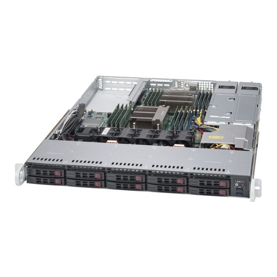
Preface Preface About This Manual This manual is written for professional system integrators and PC technicians. It provides information for the installation and use of the SuperServer 1028R-WTR(T). Installation and maintainance should be performed by experienced technicians only. The SuperServer 1028R-WTR(T) is a high-end server based on the SC116TS-R706WBP 1U rackmountable chassis and the X10DRW-i(T) dual processor serverboard. - Page 4 SUPERSERVER 1028R-WTR(T) USER'S MANUAL Chapter 6: Advanced Chassis Setup Refer to Chapter 6 for detailed information on the SC116TS-R706WBP server chassis. You should follow the procedures given in this chapter when installing, removing or reconfi guring drives and when replacing system power supply units and cooling fans.
- Page 5 Preface Notes...
-
Page 6: Table Of Contents
Cooling System ....................1-4 Advanced Power Management ............... 1-4 Intel® Intelligent Power Node Manager (IPNM) ..........1-4 Manageability Engine (ME) ................1-4 Contacting Supermicro ..................1-6 Chapter 2 Server Installation Overview ......................2-1 Unpacking the System ..................2-1 Preparing for Setup ..................2-1 Choosing a Setup Location ................ - Page 7 Table of Contents Inner Rail Extension ..................2-6 Outer Rails ...................... 2-7 Installing the Chassis into a Telco rack ............2-10 Chapter 3 System Interface Overview ......................3-1 Control Panel Buttons ..................3-1 Power ......................3-1 UID ........................3-2 Control Panel LEDs ..................3-2 Universal Information LED ................
- Page 8 SUPERSERVER 1028R-WTR(T) USER'S MANUAL Chapter 5 Advanced Serverboard Setup Handling the Serverboard ................5-1 Precautions ..................... 5-1 Unpacking ....................... 5-1 Connecting Cables ..................5-2 Connecting Data Cables ................. 5-2 Connecting Power Cables ................5-2 Connecting the Control Panel ................. 5-3 Rear I/O Ports ....................
- Page 9 Table of Contents Power Supply ....................6-7 Power Supply Failure ..................6-7 Chapter 7 BIOS Introduction ...................... 7-1 Starting BIOS Setup Utility ................7-1 How To Change the Confi guration Data ............7-2 Starting the Setup Utility ................. 7-2 Main Setup ...................... 7-2 Advanced Setup Confi...
- Page 10 SUPERSERVER 1028R-WTR(T) USER'S MANUAL Notes...
-
Page 11: Chapter 1 Introduction
SC116TS-R706WBP 1U chassis and the X10DRW-i(T) dual processor serverboard. Please refer to our web site for information on operating systems that have been certifi ed for use with the system (www.supermicro.com). In addition to the serverboard and chassis, various hardware components have been included with the SuperServer 1028R-WTR(T), as listed below: •... -
Page 12: Serverboard Features
SUPERSERVER 1028R-WTR(T) USER'S MANUAL Note: For your system to work properly, please follow the links below to download all necessary drivers/utilities and the user’s manual for your server. • Supermicro product manuals: http://www.supermicro.com/support/manuals/ • Product drivers and utilities: ftp://ftp.supermicro.com •... -
Page 13: Pci Expansion Slots
A UID (Unit Identifi er) button and LED are also located beside the VGA port. Server Chassis Features The SC116TS-R706WBP is Supermicro's third-generation 1U chassis and features ten (10) SATA-3 2.5" hard drive bays and two high-effi ciency power supplies. The following is a general outline of the main features of the SC116 chassis. -
Page 14: Cooling System
SUPERSERVER 1028R-WTR(T) USER'S MANUAL Cooling System The SC116 chassis has an innovative cooling design that features up to six sets of 4-cm counter-rotating fans located in the middle section of the chassis. These fans are 1U high and are powered by 4-pin connectors, with chassis fan speed controlled by IPMI software. - Page 15 Chapter 1: Introduction Figure 1-1. Intel PCH-C612 Chipset: System Block Diagram Note: This is a general block diagram. Please see Chapter 5 for details. SXB2 RIGHT SLOT PCIE 3.0 x16 SXB1B (lower) Left SLOT WIO Slots PCIE 3.0 x16 SXB1A SXB2 PCIE x16 Rear...
-
Page 16: Contacting Supermicro
Super Micro Computer, Inc. 980 Rock Ave. San Jose, CA 95131 U.S.A. Tel: +1 (408) 503-8000 Fax: +1 (408) 503-8008 Email: marketing@supermicro.com (General Information) support@supermicro.com (Technical Support) Web Site: www.supermicro.com Europe Address: Super Micro Computer B.V. Het Sterrenbeeld 28, 5215 ML... -
Page 17: Chapter 2 Server Installation
Chapter 2: Server Installation Chapter 2 Server Installation Overview This chapter provides a quick setup checklist to get your SuperServer 1028R-WTR(T) up and running. Following these steps in the order given should enable you to have the system operational within a minimum amount of time. This quick setup assumes that your system has come to you with the processors and memory preinstalled. -
Page 18: Warnings And Cautions
SUPERSERVER 1028R-WTR(T) USER'S MANUAL • This product is for installation only in a Restricted Access Location (dedicated equipment rooms, service closets and the like). • This product is not suitable for use with visual display work place devices acccording to §2 of the the German Ordinance for Work with Visual Display Units. Warnings and Cautions Rack Precautions •... -
Page 19: Rack Mounting Considerations
Chapter 2: Server Installation Rack Mounting Considerations Warning! To prevent bodily injury when mounting or servicing this unit in a rack, you must take special precautions to ensure that the system remains stable. The following guidelines are provided to ensure your safety: •... -
Page 20: Rack Mounting Instructions
SUPERSERVER 1028R-WTR(T) USER'S MANUAL Rack Mounting Instructions This section provides information on installing the SC116 chassis into a rack unit with the rails provided. There are a variety of rack units on the market, which may mean the assembly procedure will differ slightly. You should also refer to the installation instructions that came with the rack unit you are using. -
Page 21: Identifying The Sections Of The Rack Rails
Chapter 2: Server Installation Identifying the Sections of the Rack Rails The chassis package includes two rack rail assemblies in the rack mounting kit. Each assembly consists of two sections: an inner fi xed chassis rail that secures directly to the server chassis and an outer fi... -
Page 22: Inner Rail Extension
SUPERSERVER 1028R-WTR(T) USER'S MANUAL Figure 2-2. Identifying the Sections of the Rack Rails (right side rail shown) Inner Rail Extension The SC116 chassis includes a set of inner rails in two sections: inner rails and inner rail extensions. The inner rails are pre-attached and do not interfere with normal use of the chassis if you decide not to use a server rack. -
Page 23: Outer Rails
Chapter 2: Server Installation Figure 2-3. Assembling the Outer Rails Secure to the Front of the Rack Secure to the Rear of the Rack Attach Outer Rails together Outer Rails Installing the Outer Rails to the Rack 1. Attach the shorter outer rail to the outside of the longer outer rail. You must align the pins with the slides. - Page 24 SUPERSERVER 1028R-WTR(T) USER'S MANUAL Figure 2-4. Installing the Outer Rails to the Server Rack Note: The fi gure above is for illustrative purposes only. Always install servers to the bottom of the rack fi rst.
- Page 25 Chapter 2: Server Installation Figure 2-5. Installing the Rack Rails Installing the Chassis into a Rack 1. Confi rm that chassis includes the inner rails and inner rail extensions. Alsoconfi rm that the outer rails are installed on the rack. 2.
-
Page 26: Installing The Chassis Into A Telco Rack
SUPERSERVER 1028R-WTR(T) USER'S MANUAL Installing the Chassis into a Telco rack To install the chassis into a Telco or post-style rack, use two L-shaped brackets on either side of the chassis (four total). First, determine how far follow the server will extend out the front of the rack. -
Page 27: Chapter 3 System Interface
Chapter 3: System Interface Chapter 3 System Interface Overview There are several LEDs on the control panel and on the drive carriers that provide system and component status for the 1028R-WTR(T) server. This chapter explains the meanings of all LED indicators and the appropriate responses that need to be taken. -
Page 28: Uid
SUPERSERVER 1028R-WTR(T) USER'S MANUAL Depressing the UID (unit identifi er) button illuminates an LED on both the front and rear of the chassis for easy system location in large stack confi gurations. The LED will remain on until the button is pushed a second time. Another UID button on the rear of the chassis serves the same function. -
Page 29: Nic1
Chapter 3: System Interface NIC1 Indicates network activity on GLAN1 when fl ashing. NIC2 Indicates network activity on GLAN2 when fl ashing. Indicates IDE channel activity. SAS2/SATA drive and/or DVD-ROM drive activity when fl ashing. Power Indicates power is being supplied to the system's power supply units. This LED should normally be illuminated when the system is operating. -
Page 30: Hard Drive Carrier Leds
SUPERSERVER 1028R-WTR(T) USER'S MANUAL Hard Drive Carrier LEDs The SC116 chassis uses SATA drives. SATA Drives Each SATA drive carrier has two LEDs. • Green: Each hard drive carrier has a green LED. When illuminated, this green LED (on the front of the hard drive carrier) indicates drive activity. A connection to the SATA backplane enables this LED to blink on and off when that particular drive is being accessed. -
Page 31: Chapter 4 Standardized Warning Statements For Ac Systems
The following statements are industry standard warnings, provided to warn the user of situations which have the potential for bodily injury. Should you have questions or experience difficulty, contact Supermicro's Technical Support department for assistance. Only certifi ed technicians should attempt to install or confi gure components. - Page 32 SUPERSERVER 1028R-WTR(T) USER'S MANUAL Warnung WICHTIGE SICHERHEITSHINWEISE Dieses Warnsymbol bedeutet Gefahr. Sie befi nden sich in einer Situation, die zu Verletzungen führen kann. Machen Sie sich vor der Arbeit mit Geräten mit den Gefahren elektrischer Schaltungen und den üblichen Verfahren zur Vorbeugung vor Unfällen vertraut.
- Page 33 Warning Statements for AC Systems ﺟﺴﺪﻳﺔ ﺍﺻﺎﺑﺔ ﺗﺘﺴﺒﺐ ﻓﻲ ﺣﺎﻟﺔ ﻳﻤﻜﻦ ﺃﻥ ﺍﻧﻚ ﻓﻲ ﺧﻄﺮ ﻳﻌﻨﻲ ﻫﺬﺍ ﺍﻟﺮﻣﺰ !ﺗﺤﺬﻳﺮ ﺍﻟﺪﻭﺍﺋﺮ ﺑﺎﻟﻤﺨﺎﻁﺮ ﺍﻟﻨﺎﺟﻤﺔ ﻋﻦ ﻦ ﻋﻠﻰ ﻋﻠﻢ ، ﻛ ﻣﻌﺪﺍﺕ ﺗﻌﻤﻞ ﻋﻠﻰ ﺃﻱ ﻗﺒﻞ ﺃﻥ ﺍﻟﻜﻬﺮﺑﺎﺋﻴﺔ ﺣﻮﺍﺩﺙ ﺃﻱ ﻭﻗﻮﻉ ﻤﻨﻊ ﻟ ﺍﻟﻮﻗﺎﺋﻴﺔ...
-
Page 34: Installation Instructions
SUPERSERVER 1028R-WTR(T) USER'S MANUAL Installation Instructions Warning! Read the installation instructions before connecting the system to the power source. 警告 将此系统连接电源前,请先阅读安装说明。 警告 將系統與電源連接前,請先閱讀安裝說明。 Warnung Vor dem Anschließen des Systems an die Stromquelle die Installationsanweisungen lesen. ¡Advertencia! Lea las instrucciones de instalación antes de conectar el sistema a la red de alimentación. -
Page 35: Circuit Breaker
Chapter 4: Warning Statements for AC Systems Circuit Breaker Warning! This product relies on the building's installation for short-circuit (overcurrent) protection. Ensure that the protective device is rated not greater than: 250 V, 20 A. 警告 此产品的短路(过载电流)保护由建筑物的供电系统提供,确保短路保护设备的额定电 流不大于250V,20A。 警告 此產品的短路(過載電流)保護由建築物的供電系統提供,確保短路保護設備的額定電 流不大於250V,20A。... -
Page 36: Power Disconnection Warning
SUPERSERVER 1028R-WTR(T) USER'S MANUAL ﻓﻲ ﺍﻟﺘﻲ ﺗﻢ ﺗﺜﺒﻴﺘﻬﺎ ﻣﻦ ﺍﻟﺪﻭﺍﺋﺮﺍﻟﻘﺼﻴﺮﺓ ﺍﻟﺤﻤﺎﻳﺔ ﻣﻌﺪﺍﺕ ﻳﻌﺘﻤﺪ ﻋﻠﻰ ﻫﺬﺍ ﺍﻟﻤﻨﺘﺞ ﺍﻟﻤﺒﻨﻰ ﺃﻛﺜﺮ ﻣﻦ ﻟﻴﺲ ﻮﻗﺎﺋﻲ ﺍﻟ ﺍﻟﺠﻬﺎﺯ ﺗﻘﻴﻴﻢ ﺃﻥ ﺗﺄﻛﺪ ﻣﻦ 20A, 250V Waarschuwing Dit product is afhankelijk van de kortsluitbeveiliging (overspanning) van uw electrische installatie. - Page 37 Chapter 4: Warning Statements for AC Systems Warnung Das System muss von allen Quellen der Energie und vom Netzanschlusskabel getrennt sein, das von den Spg.Versorgungsteilmodulen entfernt wird, bevor es auf den Chassisinnenraum zurückgreift, um Systemsbestandteile anzubringen oder zu entfernen. ¡Advertencia! El sistema debe ser disconnected de todas las fuentes de energía y del cable eléctrico quitado de los módulos de fuente de alimentación antes de tener acceso el interior del chasis para instalar o para quitar componentes de sistema.
-
Page 38: Equipment Installation
SUPERSERVER 1028R-WTR(T) USER'S MANUAL Equipment Installation Warning! Only trained and qualifi ed personnel should be allowed to install, replace, or service this equipment. 警告 只有经过培训且具有资格的人员才能进行此设备的安装、更换和维修。 警告 只有經過受訓且具資格人員才可安裝、更換與維修此設備。 Warnung Das Installieren, Ersetzen oder Bedienen dieser Ausrüstung sollte nur geschultem, qualifi ziertem Personal gestattet werden. ¡Advertencia! Solamente el personal califi... -
Page 39: Restricted Area
Chapter 4: Warning Statements for AC Systems Waarschuwing Deze apparatuur mag alleen worden geïnstalleerd, vervangen of hersteld door geschoold en gekwalifi ceerd personeel. Restricted Area Warning! This unit is intended for installation in restricted access areas. A restricted access area can be accessed only through the use of a special tool, lock and key, or other means of security. -
Page 40: Battery Handling
SUPERSERVER 1028R-WTR(T) USER'S MANUAL אזור עם גישה מוגבלת !אזהרה יש להתקין את היחידה באזורים שיש בהם הגבלת גישה. הגישה ניתנת בעזרת .('כלי אבטחה בלבד )מפתח, מנעול וכד ﻣﺤﻈﻮﺭﺓ ﻣﻨﺎﻁﻖ ﻟﺘﺮﻛﻴﺒﻬﺎ ﻓﻲ ﻫﺬﻩ ﺍﻟﻮﺣﺪﺓ ﺗﺨﺼﻴﺺ ﺗﻢ ،ﺃﺩﺍﺓ ﺧﺎﺻﺔ ﻣﻦ ﺧﻼﻝ ﺍﺳﺘﺨﺪﺍﻡ ﻓﻘﻂ... - Page 41 Chapter 4: Warning Statements for AC Systems Warnung Bei Einsetzen einer falschen Batterie besteht Explosionsgefahr. Ersetzen Sie die Batterie nur durch den gleichen oder vom Hersteller empfohlenen Batterietyp. Entsorgen Sie die benutzten Batterien nach den Anweisungen des Herstellers. Attention Danger d'explosion si la pile n'est pas remplacée correctement. Ne la remplacer que par une pile de type semblable ou équivalent, recommandée par le fabricant.
-
Page 42: Redundant Power Supplies
SUPERSERVER 1028R-WTR(T) USER'S MANUAL Redundant Power Supplies Warning! This unit might have more than one power supply connection. All connections must be removed to de-energize the unit. 警告 此部件连接的电源可能不止一个,必须将所有电源断开才能停止给该部件供电。 警告 此裝置連接的電源可能不只一個,必須切斷所有電源才能停止對該裝置的供電。 Warnung Dieses Gerät kann mehr als eine Stromzufuhr haben. Um sicherzustellen, dass der Einheit kein trom zugeführt wird, müssen alle Verbindungen entfernt werden. -
Page 43: Backplane Voltage
Chapter 4: Warning Statements for AC Systems ﺍﻣﺪﺍﺩ ﺍﻟﻄﺎﻗﺔ ﺑﻮﺣﺪﺍﺕ ﻋﺪﺓ ﺍﺗﺼﺎﻻﺕ ﺠﻬﺎﺯ ﺍﻟ ﻳﻜﻮﻥ ﻟﻬﺬﺍ ﻗﺪ ﺍﻟﻜﻬﺮﺑﺎء ﻋﻦ ﻮﺣﺪﺓ ﺍﻟ ﻟﻌﺰﻝ ﻛﺎﻓﺔ ﺍﻻﺗﺼﺎﻻﺕ ﻳﺠﺐ ﺇﺯﺍﻟﺔ Waarschuwing Deze eenheid kan meer dan één stroomtoevoeraansluiting bevatten. Alle aansluitingen dienen verwijderd te worden om het apparaat stroomloos te maken. Backplane Voltage Warning! Hazardous voltage or energy is present on the backplane when the system is... -
Page 44: Comply With Local And National Electrical Codes
SUPERSERVER 1028R-WTR(T) USER'S MANUAL Attention Lorsque le système est en fonctionnement, des tensions électriques circulent sur le fond de panier. Prendre des précautions lors de la maintenance. מתח בפנל האחורי !הרה אז קיימת סכנת מתח בפנל האחורי בזמן תפעול המערכת. יש להיזהר במהלך .העבודה... -
Page 45: Product Disposal
Chapter 4: Warning Statements for AC Systems ¡Advertencia! La instalacion del equipo debe cumplir con las normas de electricidad locales y nacionales.Attention L'équipement doit être installé conformément aux normes électriques nationales et locales. תיאום חוקי החשמל הארצי !אזהרה הציוד חייבת להיות תואמת לחוקי החשמל המקומיים והארציים התקנת... -
Page 46: Hot Swap Fan Warning
SUPERSERVER 1028R-WTR(T) USER'S MANUAL Warnung Die Entsorgung dieses Produkts sollte gemäß allen Bestimmungen und Gesetzen des Landes erfolgen. ¡Advertencia! Al deshacerse por completo de este producto debe seguir todas las leyes y reglamentos nacionales. Attention La mise au rebut ou le recyclage de ce produit sont généralement soumis à des lois et/ou directives de respect de l'environnement. - Page 47 Chapter 4: Warning Statements for AC Systems 当您从机架移除风扇装置,风扇可能仍在转动。小心不要将手指、螺丝起子和其他 物品太靠近风扇 警告 當您從機架移除風扇裝置,風扇可能仍在轉動。小心不要將手指、螺絲起子和其他 物品太靠近風扇。 Warnung Die Lüfter drehen sich u. U. noch, wenn die Lüfterbaugruppe aus dem Chassis genommen wird. Halten Sie Finger, Schraubendreher und andere Gegenstände von den Öffnungen des Lüftergehäuses entfernt. ¡Advertencia! Los ventiladores podran dar vuelta cuando usted quite ell montaje del ventilador del chasis.
-
Page 48: Power Cable And Ac Adapter
fi re. Electrical Appliance and Material Safety Law prohibits the use of UL or CSA -certifi ed cables (that have UL/CSA shown on the code) for any other electrical devices than products designated by Supermicro only. 警告... - Page 49 Appareils électroménagers et de loi sur la sécurité Matériel interdit l'utilisation de UL ou CSA câbles certifi és qui ont UL ou CSA indiqué sur le code pour tous les autres appareils électriques que les produits désignés par Supermicro seulement.
- Page 50 Elektrisch apparaat en veiligheidsinformatiebladen wet verbiedt het gebruik van UL of CSA gecertifi ceerde kabels die UL of CSA die op de code voor andere elektrische apparaten dan de producten die door Supermicro alleen.
-
Page 51: Chapter 5 Advanced Serverboard Setup
Chapter 5: Advanced Serverboard Setup Chapter 5 Advanced Serverboard Setup This chapter covers the steps required to connect the data and power cables and install add-on cards. All serverboard jumpers and connections are also described. A layout and quick reference chart are included in this chapter for your reference. Remember to completely close the chassis when you have fi... -
Page 52: Connecting Cables
SUPERSERVER 1028R-WTR(T) USER'S MANUAL Connecting Cables Now that the serverboard is installed, the next step is to connect the cables to the board. These include the data cables for the peripherals and control panel and the power cables. Connecting Data Cables The cables used to transfer data from the peripheral devices have been carefully routed to prevent them from blocking the fl... -
Page 53: Connecting The Control Panel
Chapter 5: Advanced Serverboard Setup Connecting the Control Panel JF1 contains header pins for various front control panel connectors. See Figure 5-1 for the pin locations of the various front control panel buttons and LED indicators. All JF1 wires have been bundled into a single cable to simplify this connection. Make sure the red wire plugs into pin 1 as marked on the board. -
Page 54: Rear I/O Ports
SUPERSERVER 1028R-WTR(T) USER'S MANUAL Rear I/O Ports The I/O ports are in conformance with the PC 99 specifi cation. See Figure 5-2 below for the locations of the various I/O ports. Figure 5-2. Rear I/O Ports Rear I/O Ports VGA Port USB 3.0 Port 0 USB 3.0 Port 1 IPMI Dedicated LAN Port... -
Page 55: Installing The Processor And Heatsink
CPU socket cap is in place and none of the socket pins are bent; otherwise, contact your retailer immediately. • Refer to the Supermicro web site for updates on CPU support. Installing an LGA 2011 Processor Press down on the lever labeled 'Close 1st' 1. - Page 56 SUPERSERVER 1028R-WTR(T) USER'S MANUAL 3. With the lever labeled 'Close 1st' fully retracted, gently push down on the 'Open 1st' lever to open the load plate. Lift the load plate to open it completely. Gently push down to pop the load plate open.
- Page 57 Chapter 5: Advanced Serverboard Setup Caution: You can only install the CPU to the socket in one direction. Make sure that the CPU is properly inserted into the socket before closing the load plate. If it doesn't close properly, do not force it as it may damage your CPU. Instead, open the load plate again and double-check that the CPU is aligned properly.
-
Page 58: Installing And Removing A Passive Cpu Heatsink
SUPERSERVER 1028R-WTR(T) USER'S MANUAL Installing and Removing a Passive CPU Heatsink 1. Do not apply any thermal grease to the heatsink or the CPU die; the required amount has already been applied. 2. Place the heatsink on top of the CPU so that the four mounting holes are aligned with those on the serverboard and the heatsink bracket underneath. - Page 59 Chapter 5: Advanced Serverboard Setup Figure 5-3. Heatsink Placement...
-
Page 60: Installing Memory
SUPERSERVER 1028R-WTR(T) USER'S MANUAL Installing Memory Caution! Exercise extreme care when installing or removing DIMM modules to prevent any possible damage. Memory Support The X10DRW-i(T) supports up to 1024 GB of ECC registered (RDIMM) or ECC Load Reduced (LRDIMM) DDR4 2133/1866/1600/1333 MHz speed, 1 GB, 2 GB, 4 GB, 8 GB, 16 GB, 32 GB and 64 GB size @ 1.2V voltage SDRAM in sixteen (16) DIMM sockets. - Page 61 Chapter 5: Advanced Serverboard Setup DIMM Module Population Table Follow the tables below when installing memory. Processors and their Corresponding Memory Modules CPU# Corresponding DIMM Modules CPU 1 DIMMA1 DIMMB1 DIMMC1 DIMMD1 DIMMA2 DIMMB2 DIMMC2 DIMMD2 CPU2 DIMME1 DIMMF1 DIMMG1 DIMMH1 DIMME2 DIMM F2...
-
Page 62: Other Important Notes And Restrictions
64GB 2133 MHz 2133 MHz 2133 MHz Note: Please refer to our website @ http://www.supermicro.com/products/serverboard for the latest memory support updates. Other Important Notes and Restrictions • For the memory modules to work properly, please install DIMM modules of the same type, same speed and same operating frequency. -
Page 63: Serverboard Details
Chapter 5: Advanced Serverboard Setup Serverboard Details Figure 5-5. X10DRW-i(T) Layout LAN1 USB2/3(3.0)USB0/1(3.0) LAN2 UID-SW CTRL IPMI_LAN X10DRW-i(T) Rev. 1.01 CPU2 CLOSE 1st OPEN 1st BIOS LICENSE CPU1 IPMI CLOSE 1st Flash BIOS OPEN 1st I-SGPIO2 I-SGPIO1 JBT1 LED2 JPME2 JVR1 JSTBY1 Caution: 1) To avoid damaging the motherboard and its components, please do... - Page 64 SUPERSERVER 1028R-WTR(T) USER'S MANUAL X10DRW-i(T) Connectors Connectors Description AOM Slot (J35) PCI-E 3.0 x16 Add-On-Module (AOM) slot for the mezzanine HBA card Battery (JBAT1) Onboard CMOS Battery (See Chpt. 3 for used battery disposal) COM1 Backplane COM port CPU/System fan headers (Fan1-Fan4), PCH/Peripheral fan headers (FanA- Fan1-4, FanA/B FanB) Front_Panel_Control header...
- Page 65 (PN: RSC-R2UW-2E8R). Note 3: CPU2 needs to be populated for PCIe SXB2 x16 and SXB1B x16 (lower left) slots to be functional. Note 4: For the latest CPU/memory updates, please refer to our website at http:// www.supermicro.com/products/serverboard. 5-15...
-
Page 66: Connector Defi Nitions
SUPERSERVER 1028R-WTR(T) USER'S MANUAL Connector Defi nitions Power Connectors ATX Power 24-pin Connector Pin Defi nitions (JPWR1) A 24-pin main power supply connector Pin# Defi nition Pin # Defi nition (JPWR1), and two 8-pin CPU power +3.3V +3.3V connectors (JPWR2/JPWR3) are located on the serverboard. - Page 67 Chapter 5: Advanced Serverboard Setup Reset Button Reset Button Pin Defi nitions (JF1) The Reset Button connection is located Pin# Defi nition on pins 3 and 4 of JF1. Attach it to a Reset hardware reset switch on the computer Ground case.
- Page 68 SUPERSERVER 1028R-WTR(T) USER'S MANUAL Power LED Power LED Pin Defi nitions (JF1) The Power LED connection is located Pin# Defi nition on pins 15 and 16 of JF1. Refer to the 3.3V table on the right for pin defi nitions. PWR LED NMI Button NMI Button...
- Page 69 Chapter 5: Advanced Serverboard Setup Universal Serial Bus (USB) BP USB (3.0) 0/1, 2/3 Pin Defi nitions Four USB 3.0 ports (USB 0/1, USB Pin# Description 2/3) are located on the I/O backpanel. VBUS In addition, an internal USB header, SSRX- located next to S-SATA0, also provides two USB 3.0 connections (USB 4/5) for...
- Page 70 Note: UID can also be triggered via IPMI on the serverboard. For more information on IPMI, please refer to the IPMI User's Guide posted on our website @ http://www.supermicro. com. Internal Speaker Internal Buzzer Pin Defi nition The Internal Speaker (SP1) provides Pin# Defi...
- Page 71 Chapter 5: Advanced Serverboard Setup Power SMB (I C) Connector PWR SMB Pin Defi nitions Power System Management Bus (I Pin# Defi nition connector (JPI C1) monitors power Clock supply, fan and system temperatures. Data See the table on the right for pin defi...
-
Page 72: Jumper Settings
SUPERSERVER 1028R-WTR(T) USER'S MANUAL Jumper Settings Connector Pins Explanation of Jumpers To modify the operation of the Jumper serverboard, jumpers can be used to choose between optional settings. Jumpers create shorts between two Setting pins to change the function of the connector. - Page 73 Chapter 5: Advanced Serverboard Setup LAN Enable/Disable LAN Enable/Disable Jumper Settings (JPL1) JPL1 enables or disables Gigabit_ Jumper Setting Defi nition LAN ports 1/2 on the X10DRW-i, and Pins 1-2 Enabled (default) 10G_LAN ports 1/2 on the X10DRW- Pins 2-3 Disabled iT.
- Page 74 SUPERSERVER 1028R-WTR(T) USER'S MANUAL C Bus to PCI-E Slots C to PCI-E Jumper Setting Use Jumpers JI C1 and JI C2 to Jumper Setting Defi nition connect the System Management Bus Pins 1-2 Enabled C) to PCI-Express slots to improve PCI performance.
-
Page 75: Onboard Led Indicators
Chapter 5: Advanced Serverboard Setup Onboard LED Indicators GLAN LEDs GLAN LED Link Speed Activity The LAN ports are located on the IO Backplane on the serverboard. Each Ethernet LAN port has two LEDs. The GLAN Activity Indicator yellow LED indicates activity. Link LED, (Right) LED Settings located on the left side of the LAN port, Color... -
Page 76: 5-10 Sata Connections
Parallel ATA. SATA_RXP See the table on the right for pin Ground defi nitions. Note: For more information on SATA HostRAID confi guration, please refer to the Intel SATA HostRAID User's Guide posted on our website @ ftp://ftp.supermicro. com.. 5-26... -
Page 77: 5-11 Installing Software
Chapter 5: Advanced Serverboard Setup 5-11 Installing Software The Supermicro ftp site contains drivers and utilities for your system at ftp://ftp. supermicro.com. Some of these must be installed, such as the chipset driver. After accessing the ftp site, go into the CDR_Images directory and locate the ISO fi... -
Page 78: Superdoctor 5
CD on it allows you to view the entire contents. SuperDoctor 5 ® The Supermicro SuperDoctor 5 is a hardware and operating system services monitoring program that functions in a command-line or web-based interface in Windows and Linux operating systems. The program monitors system health... - Page 79 Figure 5-8. SuperDoctor 5 Interface Display Screen (Remote Control) Note: The SuperDoctor 5 program and User’s Manual can be downloaded from the Supermicro web site at http://www.supermicro.com/products/nfo/sms_sd5.cfm. For Linux, we recommend that you use the SuperDoctor II application instead. 5-29...
-
Page 80: 5-12 Serverboard Battery
SUPERSERVER 1028R-WTR(T) USER'S MANUAL 5-12 Serverboard Battery Caution: There is a danger of explosion if the onboard battery is installed upside down, which will reverse its polarites (see Figure 5-x). This battery must be replaced only with the same or an equivalent type recommended by the manufacturer (CR2032). -
Page 81: Advanced Chassis Setup
Chapter 6: Advanced Chassis Setup Chapter 6 Advanced Chassis Setup This chapter covers the steps required to install components and perform maintenance on the SC116TS-R706WBP chassis. For component installation, follow the steps in the order given to eliminate the most common problems encountered. If some steps are unnecessary, skip ahead to the step that follows. -
Page 82: Control Panel
SUPERSERVER 1028R-WTR(T) USER'S MANUAL Figure 6-1. Front and Rear Chassis Views Control Panel Hot-Swap Drive Bays (10) PCI Expansion Slot (w/ Riser Card) Power Supplies Rear I/O Ports (see Section 5-3) Control Panel The control panel (located on the front of the chassis) must be connected to the JF1 connector on the serverboard to provide you with system status indications. -
Page 83: System Fans
Chapter 6: Advanced Chassis Setup System Fans The SC116 chassis includes four (4) cooling fans. These fans are NOT redundant, hot-plug and must be replaced when they fail with the power off. The fans provide the cooling for the system. It is very important that the chassis top cover is properly installed and making a good seal in order for the cooling air to circulate properly through the chassis and cool the components. -
Page 84: Checking The Airfl Ow
SUPERSERVER 1028R-WTR(T) USER'S MANUAL Figure 6-2. Replacing a System Fan 7. Power up the system and check that the fan is working properly before replacing the chassis cover. Checking the Airfl ow Check the Airfl ow 1. Make sure there are no objects obstructing the airfl ow in and out of the server. -
Page 85: Drive Bay Installation/Removal
Chapter 6: Advanced Chassis Setup Drive Bay Installation/Removal Accessing the Drive Bays Hard Drives: Because of their hotswap capability, you do not need to access the inside of the chassis or power down the system to install or replace hard drives. Proceed to the next section for instructions. - Page 86 SUPERSERVER 1028R-WTR(T) USER'S MANUAL Removing a Hard Drive (Figure 6-4) 1. To remove a carrier, push the release button located beside the drive LEDs. 2. Swing the handle fully out and use it to pull the unit straight out. Note: Your operating system must have RAID support to enable the hot-plug capability of the hard drives.
-
Page 87: Power Supply
Chapter 6: Advanced Chassis Setup Caution: Enterprise level hard disk drives are recommended for use in Supermicro chassis and servers. For information on recommended HDDs, visit the Supermicro Web site at http://www.supermicro.com/products/nfo/fi les/storage/SAS-CompList. Note: Refer to the following FTP site for RAID setup guidelines: <ftp://ftp.supermicro. - Page 88 SUPERSERVER 1028R-WTR(T) USER'S MANUAL Figure 6-5. Removing/Replacing the Power Supply Release Tab...
-
Page 89: Chapter 7 Bios
Chapter 7: BIOS Chapter 7 BIOS Introduction This chapter describes the AMI BIOS Setup utility for the X10DRW-i(T) It also provides the instructions on how to navigate the AMI BIOS Setup utility screens. The AMI ROM BIOS is stored in a Flash EEPROM and can be easily updated. Starting BIOS Setup Utility To enter the AMI BIOS Setup utility screens, press the <Del>... -
Page 90: How To Change The Confi Guration Data
<Delete> at the appropriate time during system boot. Note: For AMI UEFI BIOS Recovery, please refer to the UEFI BIOS Recovery User Guide posted @http://www.supermicro.com/support/manuals/. Starting the Setup Utility Normally, the only visible Power-On Self-Test (POST) routine is the memory test. -
Page 91: Advanced Setup Confi Gurations
Chapter 7: BIOS Memory Information Total Memory This displays the amount of memory that is available in the system. Advanced Setup Confi gurations Use the arrow keys to select Advanced and press <Enter> to access the following submenu items: Boot Feature Quiet Boot Use this feature to select the bootup screen display between POST messages or the OEM logo. - Page 92 SUPERSERVER 1028R-WTR(T) USER'S MANUAL Bootup Num-Lock Use this feature to set the Power-on state for the Numlock key. The options are Off and On. Wait For 'F1' If Error If this feature is set to Enabled, the system will wait until the 'F1' key is pressed when an error occurs.
- Page 93 Chapter 7: BIOS CPU Confi guration This submenu displays the information of the CPU as detected by the BIOS. It also allows the user to confi gure the CPU settings. Socket 1 CPU Information/Socket 2 CPU Information This submenu displays the following information regarding the CPU installed in Socket 1 or Socket 2.
- Page 94 SUPERSERVER 1028R-WTR(T) USER'S MANUAL RTID (Record Types IDs) This feature displays the total number of Record Type IDs for local and remote pools. The options are Optimal and Alternate. Hyper-threading Select Enabled to support Intel Hyper-threading Technology to enhance CPU performance.
- Page 95 Chapter 7: BIOS DCU Streamer Prefetcher (Available when supported by the CPU) Select Enabled to support Data Cache Unite (DCU) prefetch to speed up data accessing and processing in the DCU to enhance CPU performance. The options are Disabled and Enabled. DCU IP Prefetcher Select Enabled for DCU (Data Cache Unit) IP Prefetcher support, which will prefetch IP addresses to enhance network connectivity and system performance.
- Page 96 SUPERSERVER 1028R-WTR(T) USER'S MANUAL C1E Support (Available when Power Technology is set to Custom) Select Enabled to enable Enhanced C1 Power State to boost system performance. The options are Enabled and Disabled. CPU C3 Report (Available when Power Technology is set to Custom) Select Enabled to allow the BIOS to report the CPU C3 State (ACPI C2) to the operating system.
- Page 97 Chapter 7: BIOS Long Duration Maintained This item displays the period of time (in seconds) during which long duration power is maintained. The default setting is 0. Recommended Short Duration Power Limit This item displays the short duration power settings (in watts) recommended by the manufacturer.
- Page 98 SUPERSERVER 1028R-WTR(T) USER'S MANUAL ® Intel I/OAT Select Enabled to enable Intel I/OAT (I/O Acceleration Technology), which will significantly reduce CPU overhead by leveraging CPU architectural improvements and freeing the system resource up for other tasks. The options are Disabled and Enabled. DCA Support Select Enabled to use Intel's DCA (Direct Cache Access) Technology to improve data transfer effi...
- Page 99 Chapter 7: BIOS QPI (Quick Path Interconnect) Link Speed Mode Use this feature to select data transfer speed for QPI Link connections. The options are Fast and Slow. QPI Link Frequency Select Use this feature to select the desired QPI frequency. The options are Auto, 6.4 GT/s, 7.2 GT/s, and 8.0 GT/s.
- Page 100 SUPERSERVER 1028R-WTR(T) USER'S MANUAL Channel Interleaving This feature selects from the different channel interleaving methods. The options are Auto, 1 Way, 2 Way, 3, Way, and 4 Way. Rank Interleaving This feature allows the user to select a rank memory interleaving method. The options are Auto, 1 Way, 2 Way, 4, Way, and 8 Way.
-
Page 101: South Bridge
Chapter 7: BIOS South Bridge This feature allows the user to confi gure the settings for the Intel PCH chip. PCH Information This feature displays the following PCH information. Name: This item displays the name of the PCH chip. Stepping: This item displays the PCH stepping. USB Devices: This item displays the USB devices detected by the BIOS. - Page 102 SUPERSERVER 1028R-WTR(T) USER'S MANUAL SATA Confi guration When this submenu is selected, the AMI BIOS automatically detects the presence of IDE or SATA devices and displays the following items. SATA Port0~SATA Port5: The AMI BIOS displays the status of each SATA port as detected by the BIOS.
- Page 103 Chapter 7: BIOS SATA RAID Option ROM/UEFI Driver Select Enabled to boot the system from a SATA RAID device or a UEFI (Unifi ed Extensible Firmware Interface) device. The options are Enabled or Disabled. Port 0~5 Hot Plug Select Enabled to enable hot-plug support for a port specifi ed by the user. The options are Enabled and Disabled.
- Page 104 SUPERSERVER 1028R-WTR(T) USER'S MANUAL ASPM Support This feature allows the user to set the Active State Power Management (ASPM) level for a PCI-E device. Select Auto to allow the system BIOS to automatically set the ASPM level for the system. Select Disabled to disable ASPM support. The options are Disabled and Auto.
- Page 105 Chapter 7: BIOS Super IO Confi guration Super IO Chip Displays the Super IO chip type. COM 1 Confi guration Serial Port Select Enabled to enable a serial port specifi ed by the user. The options are Enabled and Disabled. Device Settings This item displays the settings of Serial Port 1.
-
Page 106: Serial Port Console Redirection
SUPERSERVER 1028R-WTR(T) USER'S MANUAL SOL (Serial_Over_LAN) Device Mode Use this feature to select the desired mode for the SOL port. The options are Normal and High Speed. Serial Port 2 Attribute Use this feature to select the attribute for serial port 2. The options are SOL (Serial_On_LAN), and COM. - Page 107 Chapter 7: BIOS Data Bits Use this feature to set the data transmission size for Console Redirection. The options are 7 and 8 (Bits). Parity A parity bit can be sent along with regular data bits to detect data transmission errors.
- Page 108 SUPERSERVER 1028R-WTR(T) USER'S MANUAL Putty Keypad Use this feature to select function key and keypad setting on Putty. The options are VT100, LINUX, XTERMR6, SCO, ESCN, and VT400. Redirection After BIOS POST If Always Enabled is selected, Legacy Console Redirection will be enabled for Legacy OS after BIOS POST (Power-On Self Test) is completed.
-
Page 109: Acpi Settings
Chapter 7: BIOS Flow Control This feature allows the user to set the fl ow control for Console Redirection to prevent data loss caused by buffer overfl ow. Send a "Stop" signal to stop sending data when the receiving buffer is full. Send a "Start" signal to start sending data when the receiving buffer is empty. - Page 110 SUPERSERVER 1028R-WTR(T) USER'S MANUAL High Precision Event Timer Select Enabled to activate the High Precision Event Timer (HPET) that produces periodic interrupts at a much higher frequency than a Real-time Clock (RTC) does in synchronizing multimedia streams, providing smooth playback, reducing the dependency on other timestamp calculation devices, such as an x86 RDTSC Instruction embedded in the CPU.
-
Page 111: Event Logs
Chapter 7: BIOS Intel TXT(LT-SX) Confi guration This feature indicates if the following hardware components support the Intel TXT (Trusted Execution Technology), which helps protect against software-based attacks and ensures protection, confi dentiality and integrity of data stored or created on the system. - Page 112 SUPERSERVER 1028R-WTR(T) USER'S MANUAL Runtime Error Logging Support Change this item to enable or disable runtime error logging. The options are Enabled and Disabled. Memory Correction Error Threshold Change this item to defi ne the system's memory correction error threshold. Directly enter a numeric value.
-
Page 113: Ipmi
Chapter 7: BIOS IPMI Use this menu to confi gure Intelligent Platform Management Interface (IPMI) settings. System Event Log Enabling/Disabling Options SEL Components Select Enabled for all system event logging at bootup. The options are Enabled and Disabled. Erasing Settings Erase SEL Select 'Yes, On next reset' to erase all system event logs upon next system reboot. - Page 114 SUPERSERVER 1028R-WTR(T) USER'S MANUAL When SEL is Full This feature allows the user to decide what the BIOS should do when the system event log is full. Select Erase Immediately to erase all events in the log when the system event log is full. The options are Do Nothing and Erase Immediately. BMC Network Confi...
-
Page 115: Boot
Chapter 7: BIOS Boot This menu allows the user to confi gure the following boot settings for the system. Set Boot Priorities 1st Boot Device/2nd Boot Device/3rd Boot Device/4th Boot Device/5th Boot Device/6th Boot Device Use this feature to specify the sequence of boot priority for a device specifi ed by the user. -
Page 116: Security
SUPERSERVER 1028R-WTR(T) USER'S MANUAL USB Hard Disk Drive BBS Priorities This submenu allows the user to specify the boot priority sequence of a USB hard drive. 1st Device Network Device BBS Priorities This submenu allows the user to specify the boot priority sequence of a network device. -
Page 117: Save & Exit
Chapter 7: BIOS Password Check This item allows you to decide when the system should check for a password after it has been entered. Select Setup for the system to prompt for a password before the user enters the BIOS Setup utility. Select Always for the system to prompt for a password upon each system boot and before the user enters the Setup utility. - Page 118 SUPERSERVER 1028R-WTR(T) USER'S MANUAL Save Changes and Reset When you have completed the system confi guration changes, select this option to save the changes and reboot the computer so that the new system confi guration settings can take effect. Select Save Changes and Exit, and press <Enter>. When the dialog box appears, asking you if you want to exit the BIOS setup without saving, select Yes to quit BIOS without saving the changes, or select No to quit the BIOS and save changes.
- Page 119 Chapter 7: BIOS Boot Override This feature allows the user to override the Boot Option Priorities setting in the Boot menu, and instead immediately boot the system with one of the listed devices. This is a one-time override. 7-31...
- Page 120 SUPERSERVER 1028R-WTR(T) USER'S MANUAL Notes 7-32...
-
Page 121: Appendix A Bios Error Beep Codes
Appendix A: BIOS POST Error Codes Appendix A BIOS Error Beep Codes During the POST (Power-On Self-Test) routines, which are performed at each system boot, errors may occur. Non-fatal errors are those which, in most cases, allow the system to continue to boot. - Page 122 SUPERSERVER 1028R-WTR(T) USER'S MANUAL Notes...
-
Page 123: Appendix B System Specifi Cations
Appendix B: System Specifi cations Appendix B System Specifi cations Processors Single or dual Intel® Xeon E5-2600v3 Series processors Note: Please refer to our web site for a complete listing of supported processors. Chipset Intel PCH-C612 chipset BIOS 128 MB SPI AMI BIOS® SM Flash UEFI BIOS Memory Capacity Sixteen (16) DIMM slots that can support up to 1024 GB of ECC RDIMM or LRDIMM DDR4 2133/1866/1600/1333 MHz speed memory in... - Page 124 SUPERSERVER 1028R-WTR(T) USER'S MANUAL Power Supply Input Requirements AC Input Voltage: 100V - 240V AC auto-range Rated Input Current: 700W 100-140Vac: 8-6A, 50-60Hz 750W 200-240Vac: 4.3-3.8A, 50-60Hz Power Supply Output Rated Output Power: 700/750 Watt (Part# PWS-706P-1R) Rated Output Voltages: +12V (700W: 58A @ 90V-140VAC, 750W: 62A @ 180- 264VAC), +5Vsb (3A) Operating Environment Operating Temperature: 0º...
- Page 125 Appendix B: System Specifi cations Notes...
- Page 126 1028R-WTR(T) USER'S MANUAL (continued from front) The products sold by Supermicro are not intended for and will not be used in life support systems, medical equipment, nuclear facilities or systems, aircraft, aircraft devices, aircraft/emergency com- munication devices or other critical systems whose failure to perform be reasonably expected to result in signifi...
Need help?
Do you have a question about the SUPERO SUPERSERVER 1028R-WTR Series and is the answer not in the manual?
Questions and answers