
Related Manuals for Supermicro SUPERSERVER 1028R-TDW


Summary of Contents for Supermicro SUPERSERVER 1028R-TDW
- Page 1 UPER ERVER ® 1028R-TDW USER’S MANUAL 1.0a WIT.RU WIT Company – поставка серверов, СХД, сетевого оборудования, лицензионного ПО...
- Page 2 This product, including software and This manual is written for professional system integrators and PC technicians. It documentation, is the property of Supermicro and/or its licensors, and is supplied only under a provides information for the installation and use of the SuperServer 1028R-TDW.
- Page 3 Preface UPER ERVER 1028R-TDW User's Manual Notes Chapter 5: Advanced Serverboard Setup Chapter 5 provides detailed information on the X10DDW-i serverboard, including the locations and functions of connections, headers and jumpers. Refer to this chapter when adding or removing processors or main memory and when reconfiguring the serverboard.
-
Page 4: Table Of Contents
Circuit Breaker ....................4-5 Front Control Panel ..................1-3 Power Disconnection Warning ................ 4-6 Cooling System ....................1-3 Equipment Installation ..................4-8 Contacting Supermicro ..................1-5 Restricted Area ....................4-9 Chapter 2 Server Installation Battery Handling .................... 4-10 Overview ......................2-1 Redundant Power Supplies ................ - Page 5 UPER ERVER 1028R-TDW User's Manual Adding PCI Expansion Cards ............... 5-10 Mezzanine Card Installation ................5-11 Serverboard Details ..................5-12 X10DDW-i Quick Reference ................. 5-13 Connector Definitions ..................5-15 5-10 Jumper Settings .................... 5-21 5-11 Onboard Indicators ..................5-24 5-12 SATA Ports ....................5-25 5-13 Installing Software ..................
-
Page 6: Chapter 1 Introduction
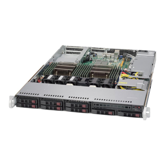
Chapter 1 Introduction Overview The SuperServer 1028R-TDW is a 1U server comprised of two main subsystems: the SC113TQ-600WB chassis and the X10DDW-i serverboard. Please refer to our website for information on operating systems that have been certified for use with the system (www.supermicro.com). -
Page 7: Serverboard Features
Hard Drive Subsystem The SC113TQ-600WB chassis was designed to support eight hot-swap SATA At the heart of the SuperServer 1028R-TDW lies the X10DDW-i, a dual processor hard drives. serverboard based on the Intel® C612 chipset. Below are the main features of the X10DDW-i. -
Page 8: Contacting Supermicro
SXB2 RIGHT SLOT Tel: +1 (408) 503-8000 PCIE 3.0 x16 Fax: +1 (408) 503-8008 SXB1B (lower) Left SLOT WIO Slots Email: marketing@supermicro.com (General Information) PCIE 3.0 x16 SXB1A SXB2 support@supermicro.com (Technical Support) PCIE x16 Rear Website: www.supermicro.com SocketID 01 PROCESSOR... - Page 9 UPER ERVER 1028R-TDW User's Manual Notes WIT.RU WIT Company – поставка серверов, СХД, сетевого оборудования, лицензионного ПО...
-
Page 10: Chapter 2 Server Installation
Unpacking the System You should inspect the box the SuperServer 1028R-TDW was shipped in and note if it was damaged in any way. If the server itself shows damage you should file a damage claim with the carrier who delivered it. -
Page 11: Choosing A Setup Location
SUPERSERVER 1028R-TDW USER'S MANUAL Chapter 2: Server Installation • Choosing a Setup Location Install the heaviest server components on the bottom of the rack first, and then • work up. Leave enough clearance in front of the rack to enable you to open the front door •... -
Page 12: Circuit Overloading
This section provides information on installing the SuperServer 1028R-TDW into a supply circuitry and the effect that any possible overloading of circuits might have rack. If the SuperServer 1028R-TDW has already been mounted into a rack, you on overcurrent protection and power supply wiring. Appropriate consideration of can skip ahead to Sections 2-5 and 2-6. -
Page 13: Inner Rails
SUPERSERVER 1028R-TDW USER'S MANUAL Chapter 2: Server Installation Inner Rails Outer Rails The SC113 chassis includes a set of inner rails in two sections: inner rails and inner Installing the Outer Rails to the Rack (Figures 2-3 and 2-4) rail extensions. The... - Page 14 SUPERSERVER 1028R-TDW USER'S MANUAL Chapter 2: Server Installation Figure 2-4. Installing the Outer Rails to the Rack Installing the Chassis into a Rack (Figure 2-5) 1. Confirm that chassis includes the inner rails and rail extensions . Also, confirm that the outer rails are installed on the rack.
- Page 15 SUPERSERVER 1028R-TDW USER'S MANUAL Notes 2-10 WIT.RU WIT Company – поставка серверов, СХД, сетевого оборудования, лицензионного ПО...
-
Page 16: Chapter 3 System Interface
Chapter 3: System Interface Chapter 3 System Interface Overview There are several LEDs on the control panel and on the drive carriers that provide system and component status for the 1028R-TDW server. This chapter explains the meanings of all LED indicators and the appropriate responses that need to be taken. Figure 3-1. -
Page 17: Control Panel Buttons
SUPERSERVER 1028R-TDW USER'S MANUAL Chapter 3: System Interface Server Interface Buttons and LEDs Depressing the UID (unit identifier) button illuminates an LED on both the front and Description rear of the chassis for easy system location in large stack configurations. The LED Power LED will remain on until the button is pushed a second time. -
Page 18: Nic2
SUPERSERVER 1028R-TDW USER'S MANUAL Chapter 3: System Interface Hard Drive Carrier LEDs Each hard drive carrier has two LEDs. • Green: When illuminated, the green LED on the front of the drive carrier NIC2 indicates drive activity. A connection to the drive backplane enables this LED to Indicates network activity on LAN2 when flashing. - Page 19 SUPERSERVER 1028R-TDW USER'S MANUAL Notes WIT.RU WIT Company – поставка серверов, СХД, сетевого оборудования, лицензионного ПО...
-
Page 20: Chapter 4 Standardized Warning Statements For Ac Systems
Only certified technicians should attempt to install or configure components. Read this appendix in its entirety before installing or configuring components in the Supermicro chassis. These warnings may also be found on our web site at http://www.supermicro.com/ about/policies/safety_information.cfm. Warning Definition Warning! This warning symbol means danger. - Page 21 Warning Statements for AC Systems UPER ERVER 1028R-TDW User's Manual Warnung جسذٌة اصابة ًتتسبب ف حالة ٌوكي أى ًاًك ف خطز ًٌٌع هذا الزهز !تحذٌز WICHTIGE SICHERHEITSHINWEISE الذوائز بالوخاطز الٌاجوة عي ي على علن ، ك هعذات تعول على أي قبل...
-
Page 22: Installation Instructions
Chapter 4: Warning Statements for AC Systems UPER ERVER 1028R-TDW User's Manual Installation Instructions Circuit Breaker Warning! Warning! This product relies on the building's installation for short-circuit (overcurrent) Read the installation instructions before connecting the system to the power source. protection. -
Page 23: Power Disconnection Warning
Chapter 4: Warning Statements for AC Systems UPER ERVER 1028R-TDW User's Manual ¡Advertencia! 경고! El sistema debe ser disconnected de todas las fuentes de energía y del cable 이 제품은 전원의 단락(과전류)방지에 대해서 전적으로 건물의 관련 설비에 eléctrico quitado de los módulos de fuente de alimentación antes de tener acceso 의존합니다. -
Page 24: Equipment Installation
Chapter 4: Warning Statements for AC Systems UPER ERVER 1028R-TDW User's Manual Equipment Installation Waarschuwing Deze apparatuur mag alleen worden geïnstalleerd, vervangen of hersteld door Warning! geschoold en gekwalificeerd personeel. Only trained and qualified personnel should be allowed to install, replace, or service Restricted Area this equipment. -
Page 25: Battery Handling
Chapter 4: Warning Statements for AC Systems UPER ERVER 1028R-TDW User's Manual Warnung אזור עם גישה מוגבלת Bei Einsetzen einer falschen Batterie besteht Explosionsgefahr. Ersetzen Sie die Batterie nur durch den gleichen oder vom Hersteller empfohlenen Batterietyp. !אזהרה Entsorgen Sie die benutzten Batterien nach den Anweisungen des Herstellers. יש... -
Page 26: Redundant Power Supplies
Chapter 4: Warning Statements for AC Systems UPER ERVER 1028R-TDW User's Manual Redundant Power Supplies امداد الطاقة بوحدات عدة اتصاالت جهاز ال يكون لهذا قد الكهرباء عن وحدة ال لعسل كافة االتصاالت يجب إزالة 경고! Warning! This unit might have more than one power supply connection. All connections must 이... -
Page 27: Comply With Local And National Electrical Codes
Chapter 4: Warning Statements for AC Systems UPER ERVER 1028R-TDW User's Manual Attention מתח בפנל האחורי L'équipement doit être installé conformément aux normes électriques nationales et locales. !הרה אז קיימת סכנת מתח בפנל האחורי בזמן תפעול המערכת. יש להיזהר במהלך תיאום... -
Page 28: Hot Swap Fan Warning
Chapter 4: Warning Statements for AC Systems UPER ERVER 1028R-TDW User's Manual ¡Advertencia! 警告 當您從機架移除風扇裝置,風扇可能仍在轉動。小心不要將手指、螺絲起子和其他 Al deshacerse por completo de este producto debe seguir todas las leyes y 物品太靠近風扇。 reglamentos nacionales. Warnung Attention Die Lüfter drehen sich u. U. noch, wenn die Lüfterbaugruppe aus dem Chassis La mise au rebut ou le recyclage de ce produit sont généralement soumis à... -
Page 29: Power Cable And Ac Adapter
UL ou CSA câbles certifiés qui ont UL ou CSA indiqué sur le code power cables and AC adaptors. Using any other cables and adaptors could cause pour tous les autres appareils électriques que les produits désignés par Supermicro a malfunction or a fire. Electrical Appliance and Material Safety Law prohibits the seulement. - Page 30 UPER ERVER 1028R-TDW User's Manual Notes 4-20 WIT.RU WIT Company – поставка серверов, СХД, сетевого оборудования, лицензионного ПО...
-
Page 31: Chapter 5 Advanced Serverboard Setup
Chapter 5: Advanced Serverboard Setup Chapter 5 Advanced Serverboard Setup This chapter covers the steps required to install processors and heatsinks to the X10DDW-i serverboard, connect the data and power cables and install add-on cards. All serverboard jumpers and connections are described and a layout and quick reference chart are included in this chapter. -
Page 32: Processor And Heatsink Installation
5. Holding the CPU carefully above • the socket, orient the CPU so Refer to the Supermicro web site for updates on CPU support. that all keys and edges will fit the socket. Installing a CPU 1. -
Page 33: Installing A Cpu Heatsink
Chapter 5: Advanced Serverboard Setup UPER ERVER 1028R-TDW User's Manual Installing a CPU Heatsink 1. Place the heatsink on top of the CPU so that the four mounting holes are Gently close aligned with those on the retention mechanism. the load plate. 7. -
Page 34: Connecting Cables
Chapter 5: Advanced Serverboard Setup UPER ERVER 1028R-TDW User's Manual Connecting Cables Figure 5-1. Front Control Panel Header Pins (JF1) Now that the processors are installed, the next step is to connect the cables to the serverboard. These include the data (ribbon) cables for the peripherals and control Ground panel and the power cables. -
Page 35: Installing Memory
DIMMG1/P2-DIMMH1 + Any memory pairs in P1, P2 DIMM slots (registered DIMMs) DDR4-2400/2133/1866/1600 memory. CPU1/CPU2 2 CPUs & P1-DIMMA1/P1-DIMMB1/P1-DIMMC1/P1-DIMMD1, P2-DIMME1/P2-DIMMF1/P2-DIM- Note: Check the Supermicro website (www.supermicro.com) for the latest memory 16 DIMMs MG1/P2-DIMMH1,P1-DIMMA2/P1-DIMMB2/P1-DIMMC2/P1-DIMMD2, P2-DIMME2/ support information. P2-DIMMF2/P2-DIMMG2/P2-DIMMH2 Populating RDIMM/LRDIMM DDR4 Memory Modules Figure 5-2. -
Page 36: Adding Pci Expansion Cards
Chapter 5: Advanced Serverboard Setup UPER ERVER 1028R-TDW User's Manual Adding PCI Expansion Cards Mezzanine Card Installation For optional SAS 3.0 support, follow the instructions below to install the AOM- PCI Expansion Slots S3108M-H8 Rev. 2.00 mezzanine card into the AOM PCI-E 3.0 slot (JMEZ1). Two riser cards are used to support PCI expansion cards. -
Page 37: Serverboard Details
Chapter 5: Advanced Serverboard Setup UPER ERVER 1028R-TDW User's Manual Serverboard Details X10DDW-i Quick Reference Jumper Description Default Setting Figure 5-4. SUPER X10DDW-i Layout JBT1 Clear CMOS See Section 5-10 C1/JI C2 SMB to PCI-E Slots Enable/Disable Pins 2-3 (Disabled) JPB1 BMC Enable/Disable Pins 1-2 (Enabled) -
Page 38: Connector Definitions
Chapter 5: Advanced Serverboard Setup UPER ERVER 1028R-TDW User's Manual Connector Definitions T-SGPIO1/2 Serial ATA (SATA) General Purpose I/O Headers for I-SATA0-5, ATX Power 24-pin Connector Pin Definitions T-SGPIO1: I-SATA0-3, T-SGPIO2: I-SATA4/5 ATX Power Connector Pin# Definition Pin # Definition Description State Status... - Page 39 Chapter 5: Advanced Serverboard Setup UPER ERVER 1028R-TDW User's Manual Power Button NIC1/NIC2 LED Indicators NIC1/2 LED The Power Button connection is The NIC (Network Interface Control- Pin Definitions (JF1) located on pins 1 and 2 of JF1. Mo- ler) LED connections for LAN ports 1 Power Button Pin# Definition...
- Page 40 Chapter 5: Advanced Serverboard Setup UPER ERVER 1028R-TDW User's Manual Internal Speaker LAN Ports Internal Buzzer Pin Definition Pin Definition The Internal Speaker (SP1) can be Pin# Definition Pin# Definition Pin# Definitions used to provide audible indications for Ethernet Ports P2V5SB SGND Pin 1...
-
Page 41: 5-10 Jumper Settings
IPMI, please refer to is on pins 1 and 2 to enable VGA. the IPMI User's Guide posted on our Pins 1-2 Enabled See the table on the right for jumper website at http://www.supermicro. Pins 2-3 Disabled settings. com. 5-20 5-21 WIT.RU... - Page 42 Chapter 5: Advanced Serverboard Setup UPER ERVER 1028R-TDW User's Manual LAN1/2 Enable/Disable Manufacture Mode Select LAN Enable/Disable Change the setting of jumper JPLAN1 Jumper Settings Close pin 2 and pin 3 of jumper to enable or disable the onboard Jumper Setting Definition JPME2 to bypass SPI flash security ME Mode Select...
-
Page 43: 5-11 Onboard Indicators
Link LED Activity LED right for the functions associated with Note also that I-SATA4/5, colored the connection speed LED. in yellow, are used with Supermicro Ground SuperDOM (Disk-on-Module) con- nectors with built-in power-pins. Su- perDOMs are backward-compatible with regular SATA HDDs and SATA Dedicated IPMI LAN LEDs DOMs. -
Page 44: 5-13 Installing Software
ERVER 1028R-TDW User's Manual 5-13 Installing Software SuperDoctor® 5 The Supermicro SuperDoctor 5 is a program that functions in a command-line or The Supermicro FTP site contains drivers and utilities for your system at ftp://ftp. web-based interface in Windows and Linux operating systems. The program moni- supermicro.com. -
Page 45: 5-14 Onboard Battery
UPER ERVER 1028R-TDW User's Manual 5-14 Onboard Battery Care must be taken to assure that the chassis cover is in place when the system is operating to assure proper cooling. Out of warranty damage to the system can occur if this practice is not strictly followed. Figure 5-7. -
Page 46: Chapter 6 Advanced Chassis Setup
Chapter 6: Advanced Chassis Setup Chapter 6 Advanced Chassis Setup This chapter covers the steps required to install components and perform maintenance on the SC113TQ-600WB chassis. For component installation, follow the steps in the order given to eliminate the most common problems encountered. If some steps are unnecessary, skip ahead to the next step. -
Page 47: Control Panel
SUPERSERVER 1028R-TDW USER'S MANUAL Chapter 6: Advanced Chassis Setup Figure 6-1. Chassis: Front and Rear Views 3. Place the new fan into the vacant space in the housing while making sure the arrows on the top of the fan (indicating air direction) point in the same... -
Page 48: Drive Bay Installation/Removal
SUPERSERVER 1028R-TDW USER'S MANUAL Chapter 6: Advanced Chassis Setup Figure 6-2. Replacing a System Fan (shown with optional fan installed) Installing a Hard Drive into a Drive Carrier (Figure 6-3) 1. Insert a drive into the carrier with the PCB side facing down and the connector end toward the rear of the carrier. -
Page 49: Dvd Drive Installation
Caution: Regardless of how many hard drives are installed, all drive carriers must remain in the drive bays to maintain proper airflow. Warning: Enterprise level hard disk drives are recommended for use in Supermicro chassis and servers. For information on recommended HDDs, visit the Supermicro website at http://www.supermicro.com/products/nfo/files/storage/SAS-CompList.pdf... -
Page 50: Power Supply
SUPERSERVER 1028R-TDW USER'S MANUAL Power Supply The SUPERSERVER 1028R-TDW has a single 600 watt power supply, which is auto-switching capable. This enables it to automatically sense and operate with a 100V to 240V input voltage. Power Supply Failure If the power supply module fails, the system will shut down and you will need to replace the module. -
Page 51: Chapter 7 Bios
When an option is selected in the left frame, it is highlighted in white. Often a text message will accompany it. Note: the AMI BIOS has default text messages built in. Supermicro retains the option to include, omit, or change any of these text messages. -
Page 52: How To Start The Setup Utility
Flashing the wrong BIOS can cause irreparable damage to the system. In no event shall as 17:30:00. Supermicro be liable for direct, indirect, special, incidental, or consequential damages arising from a BIOS update. If you have to update the BIOS, do not shut down or reset Supermicro X10DDW-i the system while the BIOS is updating to avoid possible boot failure. -
Page 53: Advanced Setup Configurations
Chapter 7: BIOS UPER ERVER 1028R-TDW User's Manual Advanced Setup Configurations Wait For 'F1' If Error Select Enabled to force the system to wait until the 'F1' key is pressed if an error Use the arrow keys to select Advanced setup and press <Enter> to access the occurs. - Page 54 Chapter 7: BIOS UPER ERVER 1028R-TDW User's Manual CPU Configuration codes to overwhelm the processor to damage the system during an attack. This feature is used in conjunction with the items: "Clear MCA," "VMX," "Enable SMX," This submenu displays the following CPU information as detected by the BIOS. It and "Lock Chipset"...
- Page 55 Chapter 7: BIOS UPER ERVER 1028R-TDW User's Manual Intel Virtualization Technology CPU C State Control (Available when Power Technology is set to Custom) Select Enable to use Intel Virtualization Technology support for Direct I/O VT-d sup- port by reporting the I/O device assignments to the VMM (Virtual Machine Monitor) Package C State limit through the DMAR ACPI tables.
- Page 56 Chapter 7: BIOS UPER ERVER 1028R-TDW User's Manual Chipset Configuration IIO2 Configuration Warning! Please set the correct settings for the items below. A wrong configuration IIO 2 IOU1 - PCIe Port setting may cause the system to malfunction. This item configures the PCI-E port Bifuraction setting for a PCI-E port specified by the user.
- Page 57 Chapter 7: BIOS UPER ERVER 1028R-TDW User's Manual Intel VT for Directed I/O (VT-d) Link L0p Enable Select Enable for Link L0p support. The options are Enable and Disable. Intel VT for Direct I/O (VT-d) Link L1 Enable Intel VT for Directed I/O (VT-d) ®...
- Page 58 Chapter 7: BIOS UPER ERVER 1028R-TDW User's Manual Socket Interleave Below 4GB Demand Scrub Select Enabled for the memory above the 4G Address space to be split between Demand Scrubbing is a process that allows the CPU to correct correctable two sockets.
- Page 59 Chapter 7: BIOS UPER ERVER 1028R-TDW User's Manual SATA Configuration USB 3.0 Support Select Enabled for USB 3.0 support. The options are Smart Auto, Auto, Enabled, When this submenu is selected, AMI BIOS automatically detects the presence of Disabled and Disabled. the SATA devices that are supported by the Intel PCH chip and displays the fol- lowing items: EHCI1...
- Page 60 Chapter 7: BIOS UPER ERVER 1028R-TDW User's Manual Port 0 ~ Port 5 Spin Up Device *If the item above "Configure SATA as" is set to IDE, the following items will display: On an edge detect from 0 to 1, set this item to allow the PCH to start a COMRE- SET initialization to the device.
- Page 61 Chapter 7: BIOS UPER ERVER 1028R-TDW User's Manual • Software Preserve Support sSATA Port 0 ~ Port 3 Spin Up Device On an edge detect from 0 to 1, set this item to allow the PCH to start a COMRE- sSATA Port 0~ Port 3 SET initialization to the device.
- Page 62 Chapter 7: BIOS UPER ERVER 1028R-TDW User's Manual PCIe/PCI/PnP Configuration PCI Device Option ROM Setting CPU1 JMEZ1 AOM PCI-E x8 (Option ROM) PCI Devices Common Settings Select Enabled to enable Option ROM support to boot the computer using a de- PCI PERR/SERR Support vice installed on the slot specified by the user.
- Page 63 Chapter 7: BIOS UPER ERVER 1028R-TDW User's Manual Data Bits Change Port 1 Settings/Change Port 2 Settings Use this feature to set the data transmission size for Console Redirection. The This feature specifies the base I/O port address and the Interrupt Request address options are 7 (Bits) and 8 (Bits).
- Page 64 Chapter 7: BIOS UPER ERVER 1028R-TDW User's Manual Putty KeyPad Parity This feature selects Function Keys and KeyPad settings for Putty, which is a A parity bit can be sent along with regular data bits to detect data transmission terminal emulator designed for the Windows OS. The options are VT100, LINUX, errors.
- Page 65 Chapter 7: BIOS UPER ERVER 1028R-TDW User's Manual Redirection After BIOS Post Flow Control Use this feature to enable or disable legacy Console Redirection after BIOS Use this item to set the flow control for Console Redirection to prevent data POST (Power-On Self-Test).
-
Page 66: Event Logs
Chapter 7: BIOS UPER ERVER 1028R-TDW User's Manual ACPI Settings Event Logs WHEA Support Use this feature to configure Event Log settings. Select Enabled to support the Windows Hardware Error Architecture (WHEA) plat- form and provide a common infrastructure for the system to handle hardware errors within the Windows OS environment to reduce system crashes and to enhance system recovery and health monitoring. -
Page 67: Ipmi
Chapter 7: BIOS UPER ERVER 1028R-TDW User's Manual Erasing Settings IPMI Erase Event Log Use this feature to configure Intelligent Platform Management Interface (IPMI) Select Enabled to erase all error events in the SMBIOS (System Management BIOS) settings. log before an event logging is initialized at bootup. The options are No, Yes, Next reset, and Yes, Every reset. -
Page 68: Security Settings
Chapter 7: BIOS UPER ERVER 1028R-TDW User's Manual Security Settings When SEL is Full This feature allows the user to determine what the AMI BIOS should do when the This menu allows the user to configure the following security settings for the system event log is full. -
Page 69: Boot Settings
Chapter 7: BIOS UPER ERVER 1028R-TDW User's Manual • Boot Settings Boot Option #9 • Use this feature to configure Boot Settings: Boot Option #10 • Boot Option #11 • Boot Option #12 • Boot Option #13 • Boot Option #14 •... -
Page 70: Save & Exit
Chapter 7: BIOS UPER ERVER 1028R-TDW User's Manual Save & Exit UEFI Application Boot Priorities • UEFI Boot Option #1 Select the Save & Exit tab from the BIOS setup screen to configure the settings below. Discard Changes and Exit Select this option to quit the BIOS setup without making any permanent changes to the system configuration, and reboot the computer. - Page 71 UPER ERVER 1028R-TDW User's Manual Restore Optimized Defaults To set this feature, select Restore Optimized Defaults from the Exit menu and press <Enter>. These are manufacture default settings designed for maximum system performance but not for maximum stability. Save as User Defaults To set this feature, select Save as User Defaults from the Exit menu and press <En- ter>.
-
Page 72: Appendix A Bios Error Beep Codes
Appendix A: BIOS POST Codes Appendix A BIOS Error Beep Codes During the POST (Power-On Self-Test) routines, which are performed at each system boot, errors may occur. Non-fatal errors are those which, in most cases, allow the system to continue to boot. - Page 73 UPER ERVER 1028R-TDW User's Manual Notes WIT.RU WIT Company – поставка серверов, СХД, сетевого оборудования, лицензионного ПО...
-
Page 74: Appendix B System Specifications
Appendix B: System Specifications Appendix B System Specifications Processors Dual Intel® Xeon E5-2600 v3/v4 series processors in an R3-LGA2011 sockets Note: Please refer to our web site for a complete listing of supported processors. Chipset Intel C612 chipset BIOS 128 MB Award® SPI Flash ROM Memory Capacity Sixteen DIMM sockets that support up to 2 TB of DDR4-2400/2133/1866/1600 LRDIMM (Load Reduced DIMMs) or 512 GB of RDIMM (registered DIMMs) - Page 75 Appendix B: System Specifications UPER ERVER 1028R-TDW User's Manual Notes Weight Gross: 44 lbs. (19.96 kg.) System Cooling Five 4-cm heavy-duty counter-rotating fans System Input Requirements AC Input Voltage: 100-240V AC auto-range Rated Input Current: 7.5 - 3.1A Rated Input Frequency: 50 to 60 Hz Power Supply Rated Output Power: 600W (Part# PWS-605P-1H) Rated Output Voltages: +3.3V (15A), +5V (18A), +12V (49A), -12V (0.5A), +5Vsb...
- Page 76 ERVER 1028R-TDW User's Manual (continued from front) The products sold by Supermicro are not intended for and will not be used in life support systems, medical equipment, nuclear facilities or systems, aircraft, aircraft devices, aircraft/emergency com- munication devices or other critical systems whose failure to perform be reasonably expected to result in significant injury or loss of life or catastrophic property damage.
Need help?
Do you have a question about the SUPERSERVER 1028R-TDW and is the answer not in the manual?
Questions and answers