Oriental motor DRL Series Operating Manual
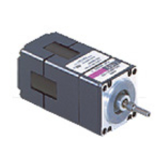
Compact linear actuator
Hide thumbs
Also See for DRL Series:
- Manual (60 pages) ,
- Operating manual (32 pages) ,
- Installation procedure (2 pages)
Table of Contents
Advertisement
Quick Links
Compact linear actuator
DRL Series
CRD driver Photocoupler inputs
OPERATING MANUAL
1
Introduction .................................................. 2
2
Safety precautions ...................................... 4
3
Precautions for use ..................................... 6
4
Preparation .................................................... 7
5
Installation ...................................................12
6
Connection ..................................................15
Thank you for purchasing an Oriental Motor product.
This Operating Manual describes product handling procedures and safety precautions.
Please read it thoroughly to ensure safe operation.
Always keep the manual where it is readily available.
7
Setting ...........................................................23
8
Inspection ....................................................32
9
remedial actions .......................................33
10
Option ..........................................................35
HP-1433-3
Advertisement
Table of Contents

Subscribe to Our Youtube Channel
Related Manuals for Oriental motor DRL Series


Summary of Contents for Oriental motor DRL Series
-
Page 1: Table Of Contents
Option ............35 Installation ...........12 Connection ..........15 Thank you for purchasing an Oriental Motor product. This Operating Manual describes product handling procedures and safety precautions. Please read it thoroughly to ensure safe operation. Always keep the manual where it is readily available. -
Page 2: Introduction
Composition and contents of this operating manual This manual describes the drivers used with the DRL series. To operate a DRL series actuator, the actuator and driver must be set up fi rst. Read the following operating manuals regarding the DRL series and follow the instructions. - Page 3 Introduction Standards and CE marking Applicable standards Motor Model Applicable Standards Certifi cation Body Standard File No. SMP, SMM, SMPG, SMMG, SMPM, SMMM, SMPH, SMMH, UL 60950 E208200 SMPGM, SMMGM, SMPGH, CSA C22.2 No.60950 SMMGH * in the motor model will contain a value representing the part number. Driver Model Applicable Standards Certifi cation Body...
-
Page 4: Safety Precautions
Safety precautions Safety precautions The precautions provided in this section are intended to ensure safe and correct use of the product, thereby preventing damage or injury to the user or other personnel. Fully understand the meaning of each item before using the product. - Page 5 Safety precautions General Do not touch the driver during operation or immediately after stopping. The surface is hot and may cause a burn. Installation Do not place fl ammable objects near the driver. Doing so may result in fi re or burns. ...
-
Page 6: Precautions For Use
Oriental Motor does not supply crimping tools. Use an actuator with electromagnetic brake for an application involving up/down travel. -
Page 7: Preparation
Open the package and confi rm that all of the following items are available. Should you fi nd any item missing or damaged, contact the Oriental Motor offi ce where you purchased the product. Check the model number of the unit against the model number on the package label. Check the model number of the actuator and driver against the model number shown on the respective nameplates. - Page 8 DRL 42 P A 2 G - 04 M G Meaning Name of the series DRL series Actuator frame size 20: 20 mm (0.79 in.) square 28: 28 mm (1.1 in.) square 42: 42 mm (1.65 in.) square 60: 60 mm (2.36 in.) square...
- Page 9 Preparation Grounded ball screw Unit model Actuator model Driver model DRL20PB1-02G DRL20PB1-02 DRL20PB1-02NG DRL20PB1-02N CRD5103P DRL20PB1G-02G DRL20PB1G-02 DRL20PB1G-02NG DRL20PB1G-02N DRL28PB1-03G DRL28PB1-03 DRL28PB1-06G DRL28PB1-06 DRL28PB1-03NG DRL28PB1-03N DRL28PB1G-03G DRL28PB1G-03 DRL28PB1G-03NG DRL28PB1G-03N DRL28MB1-03G DRL28MB1-03 DRL28MB1-03NG DRL28MB1-03N DRL28MB1G-03G DRL28MB1G-03 DRL28MB1G-03NG DRL28MB1G-03N DRL42PB2-04G DRL42PB2-04 DRL42PB2-10G DRL42PB2-10 CRD5107P...
- Page 10 Preparation Corrosion-resistant ground ball screw Unit model Actuator model Driver model DRL28PBL1-03G DRL28PBL1-03 DRL28PBL1-03NG DRL28PBL1-03N DRL28PBL1G-03G DRL28PBL1G-03 DRL28PBL1G-03NG DRL28PBL1G-03N DRL28MBL1-03G DRL28MBL1-03 DRL28MBL1-03NG DRL28MBL1-03N DRL28MBL1G-03G DRL28MBL1G-03 DRL28MBL1G-03NG DRL28MBL1G-03N DRL42PBL2-04G DRL42PBL2-04 DRL42PBL2-04MG DRL42PBL2-04M CRD5107P DRL42PBL2-04NG DRL42PBL2-04N DRL42PBL2G-04G DRL42PBL2G-04 DRL42PBL2G-04MG DRL42PBL2G-04M DRL42PBL2G-04NG DRL42PBL2G-04N DRL42MBL2-04G DRL42MBL2-04...
- Page 11 Preparation Names and functions of parts This section covers the names and functions of the driver's respective parts. See the reference page indicated for details on each part. Mounting holes MOSFET arrays Mounting holes Mounting holes Power supply connector (CN1) [p.16] Connect to a 24 VDC power supply.
-
Page 12: Installation
Installation Installation This section covers the driver's installation location and method. Location for installation The driver is designed and manufactured for use as a built-in component in industrial equipment. Install it in a well-ventilated place satisfying the following conditions, where the product can be easily accessed for the purpose of inspection. - Page 13 Conductive Noise Immunity Test IEC 61000-4-6 Power supply The DRL series products are specifi cally designed for DC power supply input. Use a DC power supply (such as a switching power supply) compliant with the EMC directive. Mains fi lter Connect a mains fi lter on the input side of the DC power supply so as to prevent the noise generated in the driver from being transmitted externally via the power supply line.
- Page 14 Installation Wiring the power supply cable and I/O cable Use a shielded cable of AWG22 (0.3 mm ) or more in diameter for the driver power supply cable. Use a shielded cable of AWG24 (0.2 mm ) or more in diameter for the driver I/O cable, and keep it as short as possible. When grounding a shielded cable, use a metal cable clamp that contacts Shielded cable the shielded cable over the entire perimeter.
-
Page 15: Connection
Connection Connection This section covers the methods of connecting the driver, actuator, power supply and controller, as well as the connection examples and I/O. DRL20, DRL28M, DRL42M, DRL60M are the connector connection cable. Use the supplied motor cable. Optional motor cables and driver cables (sold separately) are also available. See page 35 for details. Connection example ... - Page 16 Connection Current source output circuit type Driver 24 VDC±10% Lead color Blue Connector terminal number Orange Green Black Controller V0 (+5 to 24 VDC) 220 Ω PLS (CW ) 220 Ω DIR. (CCW ) 220 Ω A.W.OFF 220 Ω 220 Ω...
- Page 17 Connection Connecting the actuator Crimp-fi t the motor connector onto the motor leads and insert the connector with leads into the motor connector (CN3). To extend the motor leads, do so by using a cable of AWG22 (0.3 mm ) to AWG18 (0.75 mm ) in diameter and also by keeping the wiring length within 10 m (32.8 ft.).
- Page 18 Connection Connecting I/O signals Connector pin assignments for driver Connector No. Pin No. Type Signal Description Input +24 VDC POWER Input − Input PLS (CW) Pulse input (CW pulse) Input − Input DIR. (CCW) Rotation direction input (CCW pulse) Input −...
- Page 19 Connection Pay attention to polarity when connecting the power supply. Connecting the power supply in reverse polarity may damage the driver. Firmly insert the connector in position. Incomplete connection of the connector may cause operation failure, or may damage the actuator or driver. ...
- Page 20 Connection Standard type Guide type Input pulse signals should have a waveform with sharp rise/fall edges, as shown below. PLS input 1 μs min. 1 μs min. 10 μs min. 10 μs min. 2 μs max. 2 μs max. DIR. input ...
- Page 21 Connection Maintain driver temperature so that the surface temperature of the MOSFET array does not exceed 90 °C (194 °F). The minimum value for the interval time when switching the rotational direction depends on the actuator's size, running speed and load moment of inertia. ...
- Page 22 Connection Example of TIMING output not turning "ON" The chart below shows an operation in which the screw shaft is moved forward for 12 pulses at a resolution of 0.0004 mm (0.000016 in.) and then moved backward for one pulse at a resolution of 0.004 mm (0.00016 in.). [mm (in.)] 0.004 Forward...
-
Page 23: Setting
Setting Setting This section covers the methods of setting the resolution, switching pulse input modes, switching , smooth drive function and adjusting the motor current. Resolution When setting the actuator's resolution, use the resolution setting switches (DATA1, DATA2) and the resolution select switches (R1, R2). - Page 24 Setting DRL42 With high-resolution motors, the resolution becomes one-half the applicable value shown in the table below. Resolution Resolution Number of Number of setting switches Resolution 1 [mm (in.)] setting switches Resolution 2 [mm (in.)] divisions 1 divisions 2 DATA1/DATA2 DATA1/DATA2 0.004 (0.00016)
- Page 25 Setting The resolutions are given as theoretical values. The resolution is calculated by dividing the basic resolution by the division number. The C/S (resolution switching) input is eff ective only with respect to the division number selected for resolution 1 or resolution 2.
- Page 26 Setting Motor currents Motor operating current Factory setting: Motor's rated current Motor standstill current Factory setting: 50% of motor operating current When the load is light and there is a margin for thrust, the motor's operating vibration and the temperature increase of the motor and driver can be held down by lowering the motor's operating current and standstill current.
- Page 27 Setting CRD5114P [Representative values] 1.4 A/phase (Factory setting) The scale values are not displayed on the control. RUN potentiometer Current corresponding to a dual-phase value fl ows to the ammeter. A value of one-half that which is indicated equals the single-phase current value. Sample: When the indication value on the ammeter shows 1.5 A, it stands for the setting of 0.75 A/phase.
- Page 28 (in.)] of the DRL series, based on the following. Pulse speed and DRL series speed The relationship between the controller's pulse speed and the speed of the DRL series is as follows: DRL series speed [mm/s (in/sec)] Pulse speed [Hz] = Resolution [mm (in.)]...
- Page 29 1.2 (0.047) or less DRL60 2.4 (0.094) or less Operating speed The operating speed of the DRL series, must conform to the ranges specifi ed in the table below, including during acceleration. Unit model Starting speed [mm/s (in/sec)] DRL20 20 (0.79) or less...
- Page 30 Positioning time The following explains the formula for calculating the positioning time (reference value) of the DRL series: Since there is settling time dependent on such factors as the load's inertial moment and the speed setting, use these values only as a reference.
- Page 31 Settling time With the DRL series, the load inertial moment and other factors cause a response delay with respect to the pulse input. A delay thus caused at stopping is called the "settling time". The calculation of accurate positioning time requires that this settling time be considered.
-
Page 32: Inspection
Inspection It is recommended that the following items be checked regularly after operation. Should an abnormality be noted, discontinue any use and contact your nearest Oriental Motor offi ce. Inspection items Are there any foreign objects on the driver? ... -
Page 33: Troubleshooting And Remedial Actions
Troubleshooting and remedial actions During DRL series operation, the actuator or driver may fail to operate properly due to an error in speed setting or inappropriate connection. If the DRL series doesn't operate properly, refer to this section and take appropriate action. - Page 34 Troubleshooting and remedial actions Phenomenon Possible cause Remedial action Turn the potentiometer for adjusting the motor operating current (RUN) slightly in the counterclockwise direction in order The actuator vibrates signifi cantly. Small load. to lower the current. Vibration will increase if the actuator's output torque is too large for the load.
- Page 35 Option 10 Option Motor cable Used for actuator connection by means of connector coupling. Mode Cable length [m (ft.)] Applicable product LC5N10A DRL20, DRL28M 1 (3.3) LC5N10B DRL42M 1 (3.3) LC5N10C DRL60M 1 (3.3) Driver cable A set of three cables is provided to connect the power, I/O and motor, respectively. Model Cable length [m (ft.)] LCS04SD5...
- Page 36 If a new copy is required to replace an original manual that has been damaged or lost, please contact your nearest Oriental Motor branch or sales offi ce. Oriental Motor shall not be liable whatsoever for any problems relating to industrial property rights arising from use of any information, circuit, equipment or device provided or referenced in this manual.
Need help?
Do you have a question about the DRL Series and is the answer not in the manual?
Questions and answers