Table of Contents
Advertisement
Quick Links
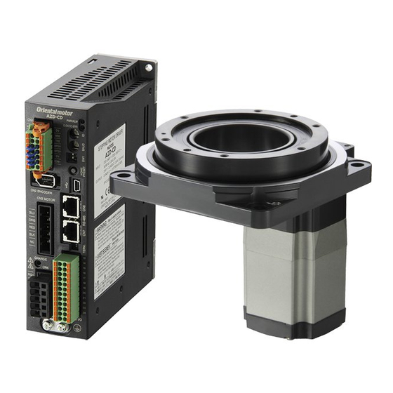
Hollow Rotary Actuators
DG Series
OPERATING MANUAL
DG85, DG130
Thank you for purchasing an Oriental Motor product.
This Operating Manual describes product handling procedures and safety precautions.
• Please read it thoroughly to ensure safe operation.
• Always keep the manual where it is readily available.
Table of Contents
Introduction .................................................... Page 2
Safety precautions ......................................... Page 4
Precautions for use ........................................ Page 6
Preparation .................................................... Page 8
Checking the product ................................. Page 8
Names and functions of parts .................... Page 10
Installation ..................................................... Page 12
Location for installation .............................. Page 12
Installing the hollow rotary actuators .......... Page 12
Installing the driver ..................................... Page 14
Installation of home-sensor set (option) ..... Page 17
Installing and wiring in compliance
with EMC directive .................... Page 19
Connection .................................................... Page 22
Connecting the hollow rotary actuators ...... Page 22
Connection example for the
control input/output .................... Page 23
Connecting to the power supply ................. Page 25
Connecting control input/output .................. Page 26
About control input/output .......................... Page 29
Timing chart ............................................... Page 34
Setting ........................................................... Page 35
Resolution .................................................. Page 35
Pulse input modes ..................................... Page 36
Operating current ....................................... Page 36
Speed filter ................................................. Page 37
Protective functions ....................................... Page 38
How to clear a protective function .............. Page 38
Inspection ...................................................... Page 39
Troubleshooting and remedial actions ........... Page 39
Main specifications ........................................ Page 41
Options (sold separately) ........................... Page 43
HG-8034
1
Advertisement
Table of Contents

Related Manuals for Oriental motor DG Series


Summary of Contents for Oriental motor DG Series
-
Page 1: Table Of Contents
Main specifications ........Page 41 Appendix Options (sold separately) ......Page 43 Thank you for purchasing an Oriental Motor product. This Operating Manual describes product handling procedures and safety precautions. • Please read it thoroughly to ensure safe operation. • Always keep the manual where it is readily available. -
Page 2: Introduction
The product described in this manual has been designed and manufactured for use in general industrial machinery, and must not be used for any other purpose. Oriental Motor Co., Ltd. is not responsible for any damage caused through failure to observe this warning. - Page 3 Quick response, high reliability used in the DG series does not allow missteps, even with a sudden change in load. The speed and amount of rotation are monitored during operation, and when the possibility of a misstep is detected due to an overload, etc., the response delay is corrected and operation continues within the maximum operating torque range.
-
Page 4: Safety Precautions
Safety precautions The precautions described below are intended to prevent danger or injury to the user and other personnel through safe, correct use of the product. Use the product only after carefully reading and fully understanding these instructions. Warning Handling the product without observing the instructions that accompany a “Warning” symbol may result in serious injury or death. - Page 5 Maintenance and inspection • Do not touch the connection terminals of the driver immediately after the power is turned off (for a period of 10 seconds). The residual voltage may cause electric shock. Repair, disassembly and modification • Do not disassemble or modify the hollow rotary actuator or driver. This may cause electric shock or injury. Refer all such internal inspections and repairs to the branch or sales office from which you purchased the product.
-
Page 6: Precautions For Use
• Operate the actuator below the permissible torque. Operating the DG series at torque outside the permissible range or keeping the output table locked may damage the gear mechanism. Be sure to operate the actuator below the permissible torque. - Page 7 • About the rotating direction of the hollow rotary actuators The CW and CCW inputs provided as driver input signals indicate the opposite directions to the output table’s direction of rotation. When the CW input is active, the output table rotates counterclockwise. When the CCW input is active, the output table rotates clockwise.
-
Page 8: Preparation
Preparation This section covers the points to be checked along with the names and functions of respective parts. Checking the product Upon opening the package, verify that the items listed below are included. Report any missing or damaged items to the branch or sales office from which you purchased the product. Verify the model number of the purchased unit against the number shown on the package label. - Page 9 Output table support bearing type R: Cross roller bearing Frame size 85 : 85 mm (3.35 in.) 130: 130 mm (5.12 in.) Series name DG series Combinations of hollow rotary actuators and drivers Unit model Hollow rotary actuators model Driver model...
-
Page 10: Names And Functions Of Parts
Names and functions of parts This section covers the names and functions of parts in the hollow rotary actuator and driver. For further details on each part, refer to the page shown in the square bracket. Hollow rotary actuators Load mounting pin holes (two locations) [P.13] Output table Load mounting screw holes (six locations) [P.13] Positioning pin holes (four locations) [P.12]... - Page 11 Driver Front side of driver ASD24A-A OPERATION (green) Lit when the power is on. OPERATION ALARM (Red) [P.38, 39] This alarm blinks when a protective function is triggered and ALARM the ALARM output turns "OFF." Count the number of blinks to ascertain the cause of triggering of the protective function.
-
Page 12: Installation
Installation This section covers the environment and method of installing the hollow rotary actuator and driver, along with load installation. Also covered in this section are the installation and wiring methods that are in compliance with the relevant EMC directives (89/336/EEC, 92/31/EEC). Location for installation The hollow rotary actuator and driver are designed and manufactured for installation in equipment. - Page 13 Securing the load to the output table Install the load with screws using the load-mounting screw holes (six locations) in the output Note table. Be sure the positioning +0.012 The output table has two load-mounting pin holes of Ø5H7 in diameter and 6 mm in depth. pins are secured to the load.
-
Page 14: Installing The Driver
Installing the driver Orientation The driver is designed so that heat is dissipated via air convection and conduction through the Note enclosure. • Install the driver in an When installing the driver in an enclosure, it must be placed in perpendicular (vertical) enclosure. - Page 15 There must be a clearance of at least 25 mm (0.98 in.) in the horizontal and vertical directions, respectively, between the driver and enclosure or other equipment within the enclosure. When two or more drivers are to be installed side by side, provide 20 mm (0.79 in.) and 25 mm (0.98 in.) clearances in the horizontal and vertical directions, respectively.
- Page 16 Mounting to DIN rail Use a DIN rail 35 mm (1.38 in.) wide to mount the driver. Attach the DIN rail mounting plate (model number: PADP01) to the back of the driver using Note • Do not use the mounting the screws supplied with the plate.
-
Page 17: Installation Of Home-Sensor Set (Option)
Installation of home-sensor set (option) Home position sensor setting details Home-sensor set (PADG-SB: NPN output, PADG-SBY: PNP output) of the following parts: Photomicrosensor 1 piece EE-SX673A (Supplied with PADG-SB, OMRON Corporation) EE-SX673R (Supplied with PADG-SBY, OMRON Corporation) Connector with cables 1 piece EE-1010-R (OMRON Corporation) length 2 m (6.6 ft.) - Page 18 Affix the shield plate to the output table using the supplied hexagonal socket head screws Note • Be sure to install the (M2.5 × 2). sensor and shield plate Tightening torque: 0.5 N·m (71 oz-in) in the direction shown in the figure.
-
Page 19: With Emc Directive
Installing and wiring Effective measures must be taken against the EMI that the DG series may give to adjacent control-system equipment, as well as the EMS of the DG series itself, in order to prevent a serious functional impediment in the machinery. - Page 20 Place the AC input cable and output cable of a mains filter separately from each other. • If an extension cable is required between the hollow rotary actuator and driver, it is recommended that an optional extension cable (sold separately) be used, since the EMC measures are conducted using the Oriental Motor extension cable.
- Page 21 Example of hollow rotary actuators and driver installation and wiring Hollow rotary actuator User controller Driver Motor cable [0.4 m (1.3 ft.)] Cable Cable Signal cable clamp clamp [2 m (6.6 ft.)] Mains filter Surge arrester (Shielded cable) Power cable Cable clamp [1.9 m (6.2 ft.)] (Shielded cable)
-
Page 22: Connection
Connection This section covers the methods and examples of connecting and grounding the driver, hollow rotary actuator, power and controller, as well as the control input/output. Connecting the hollow rotary actuators Plug the connector of the motor cable or the extension cable into the driver’s motor connector Note (CN2). -
Page 23: Control Input/Output
Connection example for the control input/output • Either 5 or 24 VDC is selected as a signal voltage for the C.OFF input, ×10 input and ACL input. Note • The TIM.1/TIM.2 outputs, ASG1/ASG2 outputs and BSG1/BSG2 outputs require a 5 or 24 VDC power. •... - Page 24 In the case of current sinking inputs and current sourcing outputs Controller Driver Note +5 V Be sure to use the same Twisted pair cable or shielded cable CW input voltage for C.OFF, ×10 CW input and ACL inputs and Photocoupler input CCW input 5 VDC Input current 7 ~ 20 mA...
-
Page 25: Connecting To The Power Supply
Connecting to the power supply Connect the power cable to the L and N terminals or the L1, L2 and L3 terminals of the power supply terminals located on the driver. For Single-phase 100-115 V unit • Single-phase 200-230 V unit Connect the live side of the power cable to the L terminal and the neutral side to the N terminal. -
Page 26: Grounding The Hollow Rotary Actuators And Driver
Grounding the hollow rotary actuators and driver Grounding the hollow rotary actuators Be sure to connect the protective ground terminal (thread size: M4) on the gear mechanism to the ground. Use a grounding cable of AWG18 (0.75 mm ) or more in diameter. Use a ground cable with insulated, covered round terminals and affix the terminal on each side using the supplied cross-head screw with a washer. - Page 27 Assembling the control input/output connector Solder the control input/output cable to the half-pitch connector (36 pins), then install the connector cover over the half-pitch connector. Soldering the cable to the half-pitch connector Solder the input/output signal cable (AWG28: 0.08 mm or more) to the half-pitch connector (36 pins).
- Page 28 Connector pin functions Note Pin No. Signal Description Direction • The functions shown in parentheses are Vcc+5 V 5 VDC External power enabled when Input source “1P: 1-Pulse Input Vcc+24 V 24 VDC Mode” is selected Not used through the pulse-input Not used mode selector switch.
-
Page 29: About Control Input/Output
About control input/output Input signals All input signals of the driver are photocoupler inputs. Note For C.OFF input, ×10 input and ACL input a signal voltage of either 5 or 24 VDC can be Be sure to use the same selected. - Page 30 1-pulse input mode Connect the pulse signal of the controller to pin No.11 and No.12, and the rotating direction signal to pin No.9 and No.10, respectively. Connect the positioning pulse input to pin No.12 PLS and the rotation direction input to pin No.10 DRE. When the DRE input is “ON,”...
- Page 31 C.OFF (All windings off) input Use the signal only when the output table must be rotated manually for position adjustment. Note • Normally, keep the Warning • Do not turn the C.OFF (All windings off) input to “ON” while the hollow C.OFF input in the rotary actuator is operating.
- Page 32 Output signals Driver output signals are photocoupler/open-collector output, transistor open-collector output Note Be sure to use the same for the TIM.1, ASG1 and BSG1 outputs, and line-driver output for the TIM.2, ASG2 and BSG2 voltage for C.OFF, ×10 outputs. and ACL inputs and The signal state represents the “ON: Carrying current”...
- Page 33 TIM. (Timing) output TIM. output are available in two types: transistor open-collector output and line-driver output. Note Use either one to suit the input system of the positioning controller. If TIM. output is to be The use of TIM. output requires separate 5 or 24 VDC power. detected, set the pulse speed at 500 Hz or less.
-
Page 34: Timing Chart
Timing chart Note Hollow rotary actuator The CW and CCW movement inputs provided as driver 10 s minimum input signals indicate the opposite directions to the Power input ∗1 output table’s direction of 0.5 s maximum rotation. 0.1 s minimum When the CW input is ALARM output active, the output table... -
Page 35: Setting
Setting This section covers the selection and settings of the driver functions. The various switches provided on the driver’s front panel allow for the setting of the resolution, pulse input mode, current level and speed filter. Warning • Before working on the system, shut off the power to the driver and wait 10 seconds. -
Page 36: Pulse Input Modes
Pulse input modes Note Either the 2-pulse or 1-pulse input mode may be selected in accordance with the controller Be sure to shut off the used. power before using the pulse input mode Factory setting selection switch. [2P]: 2-Pulse Input Mode The new pulse mode takes effect when the power is turned on... -
Page 37: Speed Filter
Speed filter Use the speed-filter selection switch “V.FIL” to select the filter time constant that determines the hollow rotary actuator’s response to pulse input. The switch provides a selection of 16 levels ranging between “0” and “F.” When a larger value is selected, it will reduce shock when the hollow rotary actuator is started and stopped, and will minimize low-speed vibration. -
Page 38: Protective Functions
Protective functions This section covers the driver-protection functions and methods used to clear the triggered function. • When the driver-protection function is triggered, the hollow rotary Warning actuator will stop and lose its holding torque, possibly causing injury or damage to equipment. •... -
Page 39: Inspection
Inspection It is recommended that periodic inspections be conducted for the items listed below after each Note operation of the hollow rotary actuator. The driver uses If an abnormal condition is noted, discontinue any use and contact your nearest office. semiconductor elements, so be extremely careful when... - Page 40 If ALARM LED is not blinking If the hollow rotary actuator does not operate properly, even though the ALARM LED is not blinking, refer to the table below: Phenomenon Possible cause Remedial action The motor windings are not Turn the C.OFF input to “OFF” and confirm that the excited, allowing the actuator to C.OFF input is “ON.”...
-
Page 41: Main Specifications
Main specifications This section covers the main specifications of the DG series. Refer to the catalog for detailed specifications, torque characteristics and dimensions. Hollow rotary actuators Driver Protective range IP40 (Motor cable countor IP20) IP10 0 to +50°C (+32 to +122°F) 0 to +50°C (+32 to +122°F) - Page 42 DG85R-ASAA DG130R-ASAA Single-phase 100-115 V DG85R-ASBA DG130R-ASBA DG130R-ASAC Unit model Single-phase 200-230 V DG130R-ASBC DG130R-ASAS Three-phase 200-230 V DG130R-ASBS Cross roller bearing Output table support bearing Permissible torque N·m (lb-in) 2.8 (2.0) 12 (106) ∗1 1.8 (15.9) 12 (106) Maximum static torque ∗2 N·m (lb-in) 15874 ×...
-
Page 43: Appendix
Appendix Options (sold separately) Extension cable Required to extend the distance between the hollow rotary actuator and driver. Model Length [m (ft.)] CC01AIP 1 (3.3) CC02AIP 2 (6.6) CC03AIP 3 (9.8) CC05AIP 5 (16.4) CC07AIP 7 (23.0) CC10AIP 10 (32.8) CC15AIP 15 (49.2) CC20AIP... - Page 44 • , and are trademarks of Oriental Motor Co., Ltd., and are registered in Japan and other countries. All other product names and company names are the trademarks or registered trademarks of their respective companies.
Need help?
Do you have a question about the DG Series and is the answer not in the manual?
Questions and answers