Oriental motor DRL II Series Operating Manual
Compact linear actuator built-in controller type
Hide thumbs
Also See for DRL II Series:
- Operating manual (16 pages) ,
- Installation procedure (2 pages)
Table of Contents
Advertisement
Quick Links
O P E R AT I N G M A N U A L
Compact Linear Actuator
Built-in controller type
Introduction
„ Before use
Only qualified personnel should work with the product.
Use the product correctly after thoroughly reading the section "Safety precautions".
The product described in this manual has been designed and manufactured for use
in general industrial machinery, and must not be used for any other purpose. For the
driver's power supply, use a DC power supply with reinforced insulation on its primary
and secondary sides.
Oriental Motor Co., Ltd. is not responsible for any damage caused through failure to
observe this warning.
„ Operating manuals for the DRLⅡSeries
Operating manuals for this product are listed below. After reading the following manuals,
keep them in a convenient place so that you can reference them at any time.
• DRLⅡSeries Actuator OPERATING MANUAL
• DRLⅡSeries FLEX Built-in Controller OPERATING MANUAL
(this document)
• CRK Series FLEX Built-in Controller USER MANUAL
The USER MANUAL for this product is common with the CRK Series.
This manual does not come with the product. For details, contact your nearest Oriental
Motor sales office.
„ CE Marking
Applicable Standards
EMI
EN 55011 group 1 class A, EN 61000-6-4, EN 61800-3
EMS
EN 61000-6-2, EN 61800-3
„ Hazardous substances
The products do not contain the substances exceeding the restriction values of RoHS
Directive (2011/65/EU).
„ Republic of Korea, Radio Waves Act
Seller and user shall be noticed that this equipment is suitable for electromagnetic
equipments for office work (Class A) and it can be used outside home.
이 기기는 업무용(A급) 전자파적합기기로서 판매자 또는 사용자는 이 점을 주의하
시기 바라며, 가정외의 지역에서 사용하는 것을 목적으 로 합니다.
„ Checking the product
Verify that the items listed below are included. Report any missing or damaged items to
the branch or sales office from which you purchased the product.
• Items supplied with all motor and driver package models
y Actuator ................................................................................ 1 unit
y Driver...................................................................................... 1 unit
y CN1 connector (3 pins) .................................................... 1 pc.
y CN2 connector cable [1 m (3.3 ft.), 40 pins] ............. 1 pc.
y CN4 connector lead wire [0.6 m (2 ft.), 5 pins] ........ 1 pc.
y OPERATING MANUAL (this document) ...................... 1 copy
y OPERATING MANUAL Actuator ..................................... 1 copy
• Item supplied with the electromagnetic brake type actuator and driver
package models
y Varistor ..............1 pc.
• Item supplied with the connector-coupled actuator and driver package
models
Applicable product: All models for the DRL20/DRL28 and models of high-resolution
motor for the DRL42/DRL60
y Actuator connector leads [0.6 m (2 ft.), 5 pins] ....... 1 pc.
DRL Ⅱ Series
MSIP-REM-OMC-078
HL-14067-3
Thank you for purchasing an Oriental Motor product. This Operating Manual describes
product handling procedures and safety precautions.
y Please read it thoroughly to ensure safe operation.
y Always keep the manual where it is readily available.
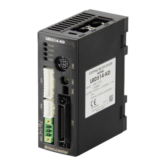
„ Names and functions of parts
• Front side of the driver
POWER LED (green)
ALARM LED (red)
C-DAT LED (green)
C-ERR LED (red)
Encoder connector (CN5)
Motor connector (CN4)
Power supply connector
Name
POWER LED (green)
ALARM LED (red)
C-DAT LED (green)
C-ERR LED (red)
Address number setting
switch (SW1)
Function setting switches
(SW2)
Power supply connector
(CN1)
I/O signals connector (CN2)
Data edit connector (CN3)
Actuator connector (CN4)
Encoder connector (CN5)
(CN1)
Description
This LED is lit while the power is input.
This LED will blink when an alarm generates (a protective
function is triggered). The type of the generated alarm
can be checked by counting the number of times the LED
blinks.
This LED will blink or illuminate steadily when the driver
is communicating with the master station properly via
RS-485 communication.
This LED will illuminate when a RS-485 communication
error occurs with the master station.
This switch is used to set the address number of RS-485
communication.
No.1 to 3: Sets the baud rate of RS-485 communication.
No.4: Sets the connection destination of RS-485
communication.
Connects the main power supply (+24 VDC) with the
supplied connector.
Connects I/O signals with the supplied lead wire/
connector assembly.
Connects a PC in which the MEXE02 has been installed,
or the OPX-2A.
Connects the actuator.
Not used.
Data edit connector
(CN3)
Address number
setting switch (SW1)
Function setting
switches (SW2)
I/O signals
connector (CN2)
DIN lever
1
Advertisement
Table of Contents

Related Manuals for Oriental motor DRL II Series


Summary of Contents for Oriental motor DRL II Series
- Page 1 (CN3) driver’s power supply, use a DC power supply with reinforced insulation on its primary and secondary sides. Oriental Motor Co., Ltd. is not responsible for any damage caused through failure to Address number Encoder connector (CN5) observe this warning.
- Page 2 • When using the LRD514-KD in parallel with another driver • Upper side of the driver Another unit can be placed in contact with the right side of LRD514-KD. Provide a clearance of 20 mm (0.79 in.) or more on the left side of LRD514-KD where a heat sink is located.
- Page 3 Setting the switches Lead wire Pin No. Signal name Description color Purple-2 HOMES Mechanical home sensor input Be sure to turn off the driver power before setting the switches. If the Gray-2 SLIT Slit sensor input switches are set while the power is still on, the new switch settings will not White-2 N.C.
- Page 4 Oriental Motor shall not be liable whatsoever for any problems relating to industrial y Do not turn the excitation to off while the actuator operates. The actuator will stop property rights arising from use of any information, circuit, equipment or device and lose its holding power.
Need help?
Do you have a question about the DRL II Series and is the answer not in the manual?
Questions and answers