Oriental motor DRL Series Operating Manual
Compact linear actuators
Hide thumbs
Also See for DRL Series:
- Manual (60 pages) ,
- Operating manual (36 pages) ,
- Installation procedure (2 pages)
Table of Contents
Advertisement
Quick Links
Compact Linear Actuators
DRL Series
Actuator with High-Strength Guide
CRD Driver
OPERATING MANUAL
1
Introduction .................................................. 2
2
Safety precautions ...................................... 4
3
Precautions for use ..................................... 6
4
Preparation .................................................... 7
5
Installation ..................................................... 9
6
Connection ..................................................12
Thank you for purchasing an Oriental Motor product.
This Operating Manual describes product handling procedures and safety precautions.
Please read it thoroughly to ensure safe operation.
Always keep the manual where it is readily available.
KCC-REM-OMC-018
7
8
9
10
Setting ...........................................................19
Inspection ....................................................27
remedial actions ........................................28
Options (sold separately) .......................30
HL-14021-3
Advertisement
Table of Contents

Subscribe to Our Youtube Channel
Related Manuals for Oriental motor DRL Series


Summary of Contents for Oriental motor DRL Series
-
Page 1: Table Of Contents
Options (sold separately) .......30 Installation ............. 9 Connection ..........12 Thank you for purchasing an Oriental Motor product. This Operating Manual describes product handling procedures and safety precautions. Please read it thoroughly to ensure safe operation. Always keep the manual where it is readily available. -
Page 2: Introduction
Compact driver The DRL series utilizes a compact driver using DC power supply input, making it ideal for use as an internal component in general industrial equipment. Preset resolution You can select and set two actuator resolutions from among the 16 levels (p.19). - Page 3 이 기기는 업무용(A급) 전자파적합기기로서 판매자 또는 사용자는 이 점을 주의하시기 바라며, 가정외의 지역 에서 사용하는 것을 목적으로 합니다. System confi guration Controllers with pulse output functions are needed to operate the DRL series. DRL series CRD driver Actuator...
-
Page 4: Safety Precautions
Safety precautions Safety precautions The precautions described below are intended to prevent danger or injury to the user and other personnel through safe, correct use of the product. Use the product only after carefully reading and fully understanding these instructions. Handling the product without observing the instructions that accompany a “Warning”... - Page 5 Safety precautions General Do not use the driver beyond its specifi cations, or injury or damage to equipment may result. Keep your fi ngers and objects out of the openings in the driver, or fi re or injury may result. ...
-
Page 6: Precautions For Use
Precautions for use Precautions for use This section covers limitations and requirements the user should consider when using the DRL series driver. Conduct the insulation resistance measurement or withstand voltage test separately on the actuator and the driver Conducting the insulation resistance measurement or withstand voltage test with the actuator and driver connected may result in injury or damage to equipment. -
Page 7: Preparation
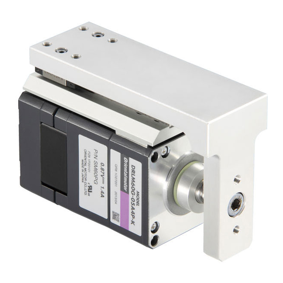
Shape V: With high-strength guide Lead 1: 1 mm (0.039 in.) A: Rolled ball screw B: Grounded ball screw Motor type P: Standard type motor Actuator frame size 20: 20 mm (0.79 in.) square 28: 28 mm (1.1 in.) square DRL series 7▐... - Page 8 Preparation Combinations of actuators and drivers Rolled ball screw Unit model Actuator model Driver model DRL28PA1V-03G DRL28PA1V-03 CRD5107P DRL28PA1V-03NG DRL28PA1V-03N Grounded ball screw Unit model Actuator model Driver model DRL20PB1V-02G DRL20PB1V-02 CRD5103P DRL20PB1V-02NG DRL20PB1V-02N DRL28PB1V-03G DRL28PB1V-03 CRD5107P DRL28PB1V-03NG DRL28PB1V-03N Names and functions of parts This section covers the names and functions of the driver’s respective parts.
-
Page 9: Installation
Installation Installation This chapter explains the installation location and installation methods of the driver, as well as how to install a load. The installation and wiring methods in compliance with the EMC Directive are also explained. Installation location The driver is designed and manufactured for installation in equipment. Install them in a well-ventilated location that provides easy access for inspection. - Page 10 Installing and wiring in compliance with EMC Directive Eff ective measures must be taken with regard to EMI caused by the DRL series actuator and/or driver in the control system equipment operating nearby and EMS of the DRL series actuator and/or driver. Failure to do so may result in serious impairment of the machine’s functionality.
- Page 11 Installation Notes about installation and wiring Connect the actuator, driver and other peripheral control equipment directly to the grounding point so as to prevent a potential diff erence from developing between grounds. When relays or electromagnetic switches are used together with the system, use mains fi lters and CR circuits to suppress surges generated by them.
-
Page 12: Connection
Connection Connection This section covers the methods and examples of connecting and grounding the driver, actuator, power supply and controller, as well as the I/O signals. DRL20 is the connector type actuator. Use the supplied connector leads. An optional connector lead wires and driver cable set is available (sold separately). - Page 13 Connection Connecting the power supply Use a power supply that can supply the current capacity shown in below. CRD5103P CRD5107P Driver model Input power supply voltage +24 VDC±10% Power supply current capacity 0.7 A or more 1.4 A or more Connecting the actuator Crimp-fi t the actuator connector onto the motor lead wires and insert the connector with leads into the actuator connector (CN3).
- Page 14 Connection Applicable connector housing and contact Connect the driver, using the supplied connector housings and contacts. Crimp motor lead wires to contact securely using the crimping tool specifi ed by the connector maker. An optional connector leads and driver cable set are also available (sold separately). See p.30 for details. ...
- Page 15 Connection Description of I/O signals Input signals The signal states indicate the state of the internal photocoupler “ON: power conducted; OFF: power not conducted”. Example of connection with Example of connection with a current sink output circuit a current source output circuit CW, CCW, A.W.OFF CW, CCW, A.W.OFF C/S, C.D.INH...
- Page 16 Connection 2-pulse input mode The controller’s CW pulses are connected to the CW+ (pin No.1) or the CW− (pin No.2), while the CCW pulses are connected to the CCW+ (pin No.3) or the CCW− (pin No.4). Turning the CW input from ON to OFF causes the moving part to move forward one step. ...
- Page 17 Connection Output signals The driver’s output signals are photocoupler/open-collector outputs. The signal states indicate the state of the internal photocoupler “ON: power conducted; OFF: power not conducted”. Example of connection with Example of connection with a current source input circuit a current sink input circuit (+5 to 24 VDC) (+5 to 24 VDC)
- Page 18 Connection Timing chart Forward Backward Backward Moving part movement 5 s or more 3 Power supply input 2-pulse input mode CW input 10 µs or more 1 300 µs or more 2 CCW input 10 µs or more 1 10 µs or more 1 1-pulse input mode PLS input DIR.
-
Page 19: Setting
Setting Setting This section explains the methods of switching or setting the drive function. Resolution When setting the actuator’s resolution, use the resolution setting switches (DATA1, DATA2) and the resolution select switch. Resolution setting switches Resolution select switch Resolution Resolution select setting switch... - Page 20 Setting How to set the resolution 1. Set the resolution select switch to R1 (ON side) or R2 (OFF side). R1 (ON side): Among the resolution shown in the table on the previous page, those corresponding to the resolution select switch setting of "R1" can be used. R2 (OFF side): Among the resolution shown in the table on the previous page, those corresponding to the resolution select switch setting of "R2"...
- Page 21 Setting Smooth drive function The smooth drive function achieves low vibration, low noise operation even in Smooth drive the basic resolution. With this function, each the basic resolution is automatically function switch (OFF/SD) divided into 16 microsteps. This function makes it not necessary to change the pulse signals (speed, pulse count) from the controller.
- Page 22 Setting Setting the motor operating current 1. Connect the motor and DC ammeter. 2. Turn the C.D.INH input to ON. Do not apply other input signals. 3. Turn on the driver’s power supply (24 VDC). 4. Adjust the operating current using the motor operating current potentiometer (RUN). Use a precision screwdriver to turn the potentiometer.
- Page 23 Resolution [mm (in.)] Number of pulses and DRL series distance of movement The relationship between the number of controller pulses and the distance the DRL series moves is as follows: DRL series distance of movement [mm (in.)] Number of pulses [pulses] = Resolution [mm (in.)]...
- Page 24 * Use the starting speed above if vibrations are generated when performing the return to mechanical home operation. Operating speed The operating speed of the DRL series must conform to the ranges specifi ed in the table below, including during acceleration. Unit model...
- Page 25 Settling time With the DRL series, the load inertial moment and other factors cause a response delay with respect to the pulse input. A delay thus caused at stopping is called the “settling time”. The calculation of accurate positioning time requires that this settling time be considered.
- Page 26 Setting Operational use of the actuator thrust The maximum thrust of the actuator is measured during constant-speed operation without loaded mass. To push or pull an external force with the actuator moving Load (jig + load) parts a thrust against the external force is required in External addition to a thrust for carrying the jig that receives the force...
-
Page 27: Inspection
Inspection Inspection It is recommended that periodic inspections be conducted for the items listed below after each operation of the actuator. If an abnormal condition is noted, discontinue any use and contact your nearest offi ce. During inspection Are there any foreign objects on the driver? ... -
Page 28: Troubleshooting And Remedial Actions
Troubleshooting and remedial actions Troubleshooting and remedial actions During operation, the actuator or driver may fail to function properly due to an improper speed setting or wiring. When the actuator cannot be operated correctly, refer to the contents provided in this section and take appropriate action. - Page 29 Troubleshooting and remedial actions Phenomenon Possible cause Remedial action Check for large load fl uctuations during actuator operation. If adjusting the operating Large load or signifi cant load speed to low and high torque eliminates the fl uctuation. problem, it is necessary to review the load conditions.
-
Page 30: Options (Sold Separately)
Options (sold separately) 10 Options (sold separately) Connector leads Used for actuator connection by means of connector coupling. Model name Length Applicable product LC5N10A DRL20 1 m (3.3 ft) Driver cable set A set of lead wires preassembled with a crimped connector matching the driver-side connector. A set of three cables is provided to connect the power supply, actuator and I/O signals, respectively. - Page 31 31▐...
- Page 32 If a new copy is required to replace an original manual that has been damaged or lost, please contact your nearest Oriental Motor branch or sales offi ce. Oriental Motor shall not be liable whatsoever for any problems relating to industrial property rights arising from use of any information, circuit, equipment or device provided or referenced in this manual.
Need help?
Do you have a question about the DRL Series and is the answer not in the manual?
Questions and answers