Oriental motor DRL Series Operating Manual
Compact linear actuator
Hide thumbs
Also See for DRL Series:
- Manual (60 pages) ,
- Operating manual (36 pages) ,
- Installation procedure (2 pages)
Table of Contents
Advertisement
Quick Links
Compact linear actuator
DRL
Series
Actuator
OPERATING MANUAL
Thank you for purchasing an Oriental Motor product.
This operating manual describes product handling
procedures and safety precautions.
Please read it thoroughly to ensure safe operation.
●
●
Always keep the manual where it is readily available.
Table of Contents
Before using this product ............ Page 3
Introduction ........................... Page 3
Names and functions of parts ...... Page 4
Safety precautions .................. Page 6
Precautions for use .................. Page 7
Installation .............................. Page 9
Location for installation ............ Page 9
Installing the actuator ............... Page 9
Installing a load ..................... Page 13
Connection .............................. Page 16
Connecting the driver ............... Page 16
Operation ................................. Page 17
temperature ........................... Page 17
Screw shaft projection ............... Page 17
Maintenance/Inspection ............ Page 18
Options .................................... Page 19
HP-1426-5
Advertisement
Table of Contents

Subscribe to Our Youtube Channel
Related Manuals for Oriental motor DRL Series


Summary of Contents for Oriental motor DRL Series
-
Page 1: Table Of Contents
………… Page 17 Operating speed at low temperature ……………………… Page 17 Screw shaft projection …………… Page 17 Thank you for purchasing an Oriental Motor product. This operating manual describes product handling Maintenance/Inspection ………… Page 18 procedures and safety precautions. - Page 2 Composition and contents of this operating manual This manual describes the actuators used with the DRL series. To operate a DRL series actuator, the actuator and driver must be set up first. Read the following operating manuals regarding the DRL series and follow the instructions.
-
Page 3: Before Using This Product
This section covers the main features and system configuration. ■ Main features The compact linear actuator DRL series is a family of linear motion actuators adopting a new mechanism: a 5-phase stepping motor incorporating a ball screw. ■ System configuration Operating the DRL series requires a controller equipped with a pulse output function. -
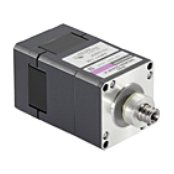
Page 4: Names And Functions Of Parts
Names and functions of parts This section covers the names and functions of the actuator’s respective parts. See the reference page indicated for details on each part. ■ Standard type Illustration shows the DRL60P standard type. Adjustment knob [Applicable only to adjustment knob type] P.17 Use this knob to adjust the position Motor... - Page 5 ■ Guide type Illustration shows the DRL60P Guide type. Electromagnetic brake [Applicable only to the DRL42 and DRL60 with electromagnetic brake type] Load-mounting taps Non-excitation operation P.15 (four locations) electromagnetic brake (24 VDC input). P.14 Joint Linear guide A moving part of the actuator. This serves as the anti-spin mechanism for the ball screw.
-
Page 6: Safety Precautions
Safety precautions This product is designed for incorporation into industrial equipment. Touching the product during operation may result in bodily injury or property damage, since the screw shaft is rotating and the surface of the actuator remains very hot. To prevent bodily injury or damage to the product, be sure the product is handled and operated only by qualified personnel familiar with operations involving electronic equipment. -
Page 7: Precautions For Use
Precautions for use This section covers the limitations and points to note regarding use of the DRL series actuator. ■ ■ Maximum thrust force Grease on screw shaft Always operate the actuator under a load not Grease on the screw shaft may darken slightly exceeding the maximum thrust force. - Page 8 ■ Guide type The linear guide of the guide type is mainly used as the anti-spin mechanism. Do not apply a load moment to the linear guide of the DRL20 and DRL28. The DRL42 and DRL60 can withstand a slight load moment using the load-mounting taps at the joint.
-
Page 9: Installation
Installation This section covers the actuator’s installation location and method, as well as the method for installing a load. Location for installation Installing the actuator The actuator is designed and manufactured for use Install the actuator to a rigid metal plate. A mounting plate (model: PADRL-□□) is available as a built-in component in industrial equipment. - Page 10 ■ Plate cutout for mounting Unit = mm (inch) ● Standard type L 0.1 (L 0.004) DRL20 DRL28 DRL42 DRL60 16 (0.63) 23 (0.906) 31 (1.22) 50 (1.969) 2.3 (0.09) 3 (0.12) 4.5 (0.18) 5.5 (0.22) 16 to 17 (0.63 to 0.67) 22 to 23 (0.87 to 0.91) 25 to 27 (0.98 to 1.06) 36 to 38 (1.42 to 1.5) ●...
-
Page 11: Installing The Actuator Using A Mounting Plate Padrl-□□ (Sold Separately)
Installing the actuator using a mounting plate PADRL-□□ (sold separately) ● Guide type Installing the actuator and mounting plate Illustration shows the DRL60P Guide type. Install the mounting plate to the actuator by tightening the supplied screws (four pieces) into the tapped holes. - Page 12 Mounting to the equipment Mount the mounting plate to the equipment using two screws (not supplied). Three methods are available. ● ● Type C Type A Nominal diameter Effective depth Tightening torque Nominal diameter Tightening torque Model Model [mm (inch)] [N·m (oz-in)] [N·m (oz-in)] of bolt...
-
Page 13: Installing A Load
Installing a load NOTE When installing a load to the DRL20 and DRL28 ■ Standard type standard type, chamfer the load-mounting hole by a factor of 0.1 (0.004). Chamfering the end face of the The standard type cannot be operated without an screw shaft may result in a malfunctioning actuator anti-spin mechanism for the screw shaft. - Page 14 ■ Guide type Affix the load with a screw. Screw NOTE ● Do not apply an overhung load to the joint of the guide type. Also, do not apply a load moment to the joint of the DRL20 and DRL28 guide type. Load mounting taps Doing so may result in a malfunction or shorter service life of the actuator.
- Page 15 ● When using load-mounting taps on the linear guide side Install the load using load-mounting taps at the joint and appropriate screws (not supplied with the product). Screw Load mounting taps 0.012) Tightening Nominal Effective depth Model diameter torque [mm (inch)] [mm (inch)] [mm (inch)] of bolt...
-
Page 16: Connection
Connection ■ Connecting power supply for Connecting the driver the electromagnetic brake See the operating manual for the driver. The electromagnetic brake operates via the ON/OFF Connecting the electromagnetic status of the DC power supply. For the electromagnetic brake, provide a power source of brake 24 VDC ±... -
Page 17: Operation
Operation Screw shaft projection How to use the adjustment knob With actuators whose stroke is 60 mm (2.36 inch) or more, the long screw shaft projects from the end (Applicable only to adjustment knob type) face of the actuator as shown in the figure. For Use this knob to adjust the position when the these actuators, provide a sufficient space in the power is off by manually moving the screw shaft. -
Page 18: Maintenance/Inspection
Maintenance/Inspection It is recommended that the following items be checked regularly after operation. Should an abnormality be noted, discontinue any use and contact your nearest Oriental Motor office. ■ Inspection items Are there any loose actuator-mounting screws ? ● ●... -
Page 19: Options
Options ■ Motor cable Used for actuator connection by means of connector coupling. Model Cable length [m (ft.)] Applicable product LC5N10A DRL20, DRL28M 1 (3.3) LC5N10B DRL42M 1 (3.3) LC5N10C DRL60M 1 (3.3) ■ Connector set (Molex) A set of connector housings and contacts matching a connector-type actuators. Each bag contains enough housings and contacts for connecting 30 actuators. - Page 20 • Please contact your nearest Oriental Motor o ce for further information. Singapore Korea Technical Support Tel:(800)468-3982 Tel:1800-8420280 Tel:080-777-2042 8:30 to 5:00 , P.S.T. (M-F) A.M. P.M. www.orientalmotor.com.sg www.inaom.co.kr 7:30 to 5:00 , C.S.T. (M-F) A.M. P.M. www.orientalmotor.com Tel:1800-806161 Hong Kong Branch Tel:+55-11-3266-6018 www.orientalmotor.com.my...
Need help?
Do you have a question about the DRL Series and is the answer not in the manual?
Questions and answers