Advertisement
Quick Links
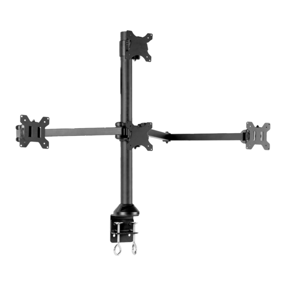
Quad Monitor Desk Mount
Instruction Manual
SKU: STAND-V104A
Scan the QR code with your mobile device or follow the link
for helpful videos and specifications related to this product.
https://vivo-us.com/products/stand-v104a
GET IN TOUCH | Monday-Friday from 7:00am-7:00pm CST
help@vivo-us.com
www.vivo-us.com
Chat live with an agent!
309-278-5303
Advertisement

Subscribe to Our Youtube Channel
Related Manuals for Vivo STAND-V104A


Summary of Contents for Vivo STAND-V104A
- Page 1 Quad Monitor Desk Mount Instruction Manual SKU: STAND-V104A Scan the QR code with your mobile device or follow the link for helpful videos and specifications related to this product. https://vivo-us.com/products/stand-v104a GET IN TOUCH | Monday-Friday from 7:00am-7:00pm CST help@vivo-us.com www.vivo-us.com...
- Page 2 WARNING! If you do not understand these directions, or if you have any doubts about the safety of the installation, please call a qualified technician. Check carefully to make sure there are no missing or defective parts. Improper installation may cause damage or serious injury.
-
Page 3: Package Contents
PACKAGE CONTENTS A (x1) B (x1) C (x1) D (x1) E (x1) Pole Clamp Clamp Brace Decorative Center Cover Monitor Arm F (x2) G (x1) H (x1) I (x1) J (x4) Monitor Arm Mount Support Plate Foam Pad Monitor Arm Cover K (x2) L (x4) -
Page 4: Assembly Steps
ASSEMBLY STEPS STEP 1 - Clamp Installation Install Pole (A) to Clamp Brace (C) using M6x10mm Screws (S-C) and a Phillips screwdriver. Assemble Clamp (B) to Clamp Brace (C) using M10x15mm Screws (S-D) and 5mm Allen Wrench (T-B). Secure the clamp assembly to the desktop be tightening to the hand bolts on Clamp Brace (C). Install the Pole Cover (D) to Pole (A). - Page 5 STEP 1 - Grommet Installation Remove adhesive backing from Foam Pad Pad (I) and place on the bottom of Pole (A). Install Pole (A) to existing grommet hole using Support Plate (H) with M10x100mm Screw (S-B), M10 Washer (S-G) and Spring Washer (S-F). Tighten with Wrench (T-D). Install the Pole Cover (D) to Pole (A).
- Page 6 STEP 2 Lay Monitor Arm (F) on flat surface with holes for cable clips facing down. Add Plastic Spacers (L) to holes at ends of Monitor Arm (F). Cable Clip Hole Cable Clip Hole NOTE: Transparent monitor arm image used to show cable clip holes. Holes are on the underside of arms and are not visable when arm is facing upright.
- Page 7 STEP 3 Slide arm assembly onto Pole (A) at desired height and secure using M8x10mm Screws (S-E) and 5mm Allen Wrench (T-B). STEP 4a - Flat Back Monitors Attach the Center VESA Plates (P) to the monitors you intend to mount in the center of the mount. Attach Side VESA Plates (O) to remaining monitors.
- Page 8 STEP 4b - Curved/Recessed Back Monitors Attach the Center VESA Plates (O) to the monitors you intend to mount in the center of the mount. Attach Side VESA Plates (N) to remaining monitors. Secure using M4 Spacers (M-C), M4x30mm Screws (M-B) and a Phillips screwdriver. Center VESA Plate (O) Installation Side VESA Plate (N) Installation STEP 5...
- Page 9 STEP 6 Slide the outer monitors onto Outer VESA Heads (F1). Secure with Cap Nut (S-F). Adjust Monitor Tilt Pry off Plastic Covers (F2) from the Outer VESA Heads (F1). The exposed nut on the side is used to adjust the tilt. Tighten the nut using Wrench (T-D) to adjust.
- Page 10 Adjust Monitor Height To adjust center monitor height, turn the screw behind Center Head (E1) and Mount (G) using the 5mm Allen Wrench (T-B). To level the side monitors, remove the Cap Nut (S-F) and turn the inner bolt with the 3mm Allen Wrench (T-A) to raise or lower the monitor.
-
Page 11: Cable Management
Cable Management Manage cables using Cable Clips (M) on assembled arms. Remove the split cap from the Pole (A) and feed cables through, pulling ends out from the opening in back. Replace the split cap when finished. - Page 12 : 1HR 8M (within office hrs) - 23% within < 15m - 38% within < 30m - 61% within < 1hr - 83% within < 2hr - 92% within < 3hr FOR MORE VIVO PRODUCTS, CHECK OUT OUR WEBSITE AT: www.vivo-us.com...
Need help?
Do you have a question about the STAND-V104A and is the answer not in the manual?
Questions and answers