
Subscribe to Our Youtube Channel
Related Manuals for Beckhoff C6250-0070


Summary of Contents for Beckhoff C6250-0070
- Page 1 Installation and Operating instructions for Control Cabinet PC C6250 from -0070 Version: 3.0 Date: 2020-04-24...
-
Page 3: Table Of Contents
First switching on and driver installation Maintenance Cleaning the Industrial PC Replacing the battery on the motherboard Servicing Shutting down Disposal Troubleshooting Fault correction Service and Support Beckhoff's branch offices and representatives Beckhoff headquarters Beckhoff Support Beckhoff Service Assembly dimensions C6250... - Page 4 Table of contents Appendix Technical data Approvals FCC: Federal Communications Commission Radio Frequency Interference Statement FCC: Canadian Notice C6250...
-
Page 5: General Instructions
All the components are supplied in particular hardware and software configurations appropriate for the application. Modifications to hardware or software configurations other than those described in the documentation are not permitted, and nullify the liability of Beckhoff Automation GmbH & Co.KG. Delivery conditions In addition, the general delivery conditions of the company Beckhoff Automation GmbH &... -
Page 6: Description Of Safety Symbols
General instructions Description of safety symbols The following safety symbols are used in this operating manual. They are intended to alert the reader to the associated safety instructions. This symbol is intended to highlight risks for the life or health of personnel. Danger This symbol is intended to highlight risks for equipment, materials or the environment. -
Page 7: Operator's Obligation To Exercise Diligence
General instructions Operator's obligation to exercise diligence The operator must ensure that • the Industrial PC is only used for its intended use (see also Product Description). • the Industrial PC is in a sound condition and in working order during operation. -
Page 8: Product Description
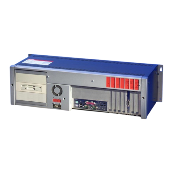
Product Description Product Description Appropriate Use The C6250 Industrial PC is designed for mounting in control cabinets in machine and plant engineering applications. The ambient conditions specified in the technical data (see Appendix) must be observed for both operation and storage of the C6250 Industrial PC. Structure Front view of the C6250 (Similar photograph) - Page 9 Product Description View of the open PC Under the housing cover (1) is a 7 slot computer core with standard ATX motherboard (2) and power supply unit (3). The connections are located at the front of the housing (4). C6250...
-
Page 10: Interfaces From C6250-0070
The four USB interfaces (X108 – X111) are used to connect peripheral devices with USB connections: ▪ Devices with Intel ® generation processors (C6250-0070) are equipped with 2 USB2.0 (X110, X111) and 2 USB3.0 (X108, X109) interfaces. ▪ Devices from Intel ®... -
Page 11: Installation Instructions
4. Please keep the associated paperwork. It contains important information for handling the unit. 5. Check the contents for visible shipping damage. 6. If you notice any shipping damage or inconsistencies between the contents and your order, you should notify Beckhoff Service. C6250... -
Page 12: Installation Of The Pc In The Control Cabinet
Installation Instructions Installation of the PC in the control cabinet The C6250 Industrial PC is designed for mounting in control cabinets in machine and plant engineering applications. The ambient conditions specified for operation must be observed (see the section on Technical data). -
Page 13: Power Supply Connection
Installation Instructions Power Supply Connection The 5-pin CAGE CLAMP plug connector and mounting flange illustrated is located on the PC housing in order to connect the power supply. Socket at the PC housing Technical data Connecting socket Number of contacts Contact spacing 5 mm Minimum conductor cross-section... -
Page 14: Fitting The Power Supply Cable
Installation Instructions Fitting the Power Supply Cable Coding pieces The connectors are coded differently at the factory, using snap-on coding pieces, according to the power supply unit that has been fitted. Differently coded plug connectors Coding for the 24 V power supply Coding for the 100-240 V 50-60 Hz power supply unit... -
Page 15: Pin Assignment And Cable Requirements
Installation Instructions Pin assignment and cable requirements Pin assignment There is an adhesive label with the pin assignments on the top of the female plug connector. The minimum permitted conductive cross- section is 1.5 mm², fused for 10 A (AWG 16). Industrial PCs with 100-240 V , 50-60 Hz power supply unit Pin assignment for the... -
Page 16: Connecting Power Supply
Installation Instructions 5. Fix the upper part (part B) of the strain relief housing by snapping it onto the lower part. Connecting Power Supply The external wiring consists of the connection of the power supply, the battery pack (optional) and the connection of customized components for shutting down the PC. -
Page 17: Wiring Diagram
Installation Instructions Wiring Diagram Wiring according to the wiring diagram (the circuit of PC_ON and Power- Status is symbolical): Wiring diagram external switch and power supply Connection of the Battery Pack and UPS Output only in combination with integrated UPS (order option). C6250... -
Page 18: Connecting Devices
Installation Instructions Connecting devices The power supply plug must be withdrawn! Warning Please read the documentation for the external devices prior to connecting them. During thunderstorms, plug connector must neither be inserted nor removed. When disconnecting a plug connector, always handle it at the plug. Do not pull the cable! Connecting cables The connections are located on the front of the Industrial PC, and are... -
Page 19: Operating Instructions
Operating Instructions Operating Instructions Please also refer to chapter General instructions. Switching the Industrial PC on and off Switch on The Industrial PC does not have its own mains switch. When the plant is switched on, or when it is connected to its power supply, the Industrial PC will start up. -
Page 20: Maintenance
Operating Instructions Maintenance Please also refer to chapter General instructions. Cleaning the Industrial PC Switch off the Industrial PC and all connected devices, and disconnect the Industrial PC from the power supply. Danger The Industrial PC can be cleaned with a soft, damp cloth. Do not use any aggressive cleaning materials, thinners, scouring material or hard objects that could cause scratches. -
Page 21: Troubleshooting
Nothing happens after the Industrial No power supply to the Industrial Check power supply cable. PC has been switched on Other cause. Call Beckhoff Service. The Industrial PC does not boot Floppy disk or CD in the drive. Remove floppy disk or CD fully and press any key. -
Page 22: Service And Support
Fax: +49(0)5246/963-198 e-mail: info@beckhoff.com Beckhoff Support Support offers you comprehensive technical assistance, helping you no only with the application of individual Beckhoff products, but also with other, wide-ranging services: • world-wide support • design, programming and commissioning of complex automation systems •... -
Page 23: Assembly Dimensions
Assembly dimensions Assembly dimensions The following pages show diagrams of the Industrial PC, with dimensions in mm. The assembly of the unit must take place with the orientation diagrammed here. Warning Horizontal Installation Side View Front View Top View C6250... - Page 24 The assembly of the unit must take place with the orientation diagrammed here. Warning Vertical Installation Side View Front View Top View C6250...
- Page 25 Appendix Appendix Technical data Dimensions Dimensions (W x H x D): 680 x 184 x 268 mm Weight: 22.2 kg (basic configuration) Do not use the PC in areas The Industrial PC may not be used in areas of explosive hazard. of explosive hazard The following conditions must be observed during operation: Environmental conditions...
Need help?
Do you have a question about the C6250-0070 and is the answer not in the manual?
Questions and answers