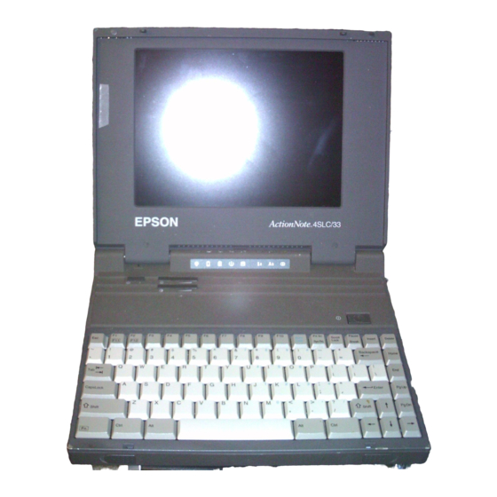
Epson ActionNote 4SLC/33 User Manual
Hide thumbs
Also See for ActionNote 4SLC/33:
- Specification sheet (7 pages) ,
- Product support bulletin (10 pages)
Table of Contents
Advertisement
Quick Links
Advertisement
Table of Contents

Related Manuals for Epson ActionNote 4SLC/33


Summary of Contents for Epson ActionNote 4SLC/33
- Page 2 This equipment has been tested and found to comply with the limits for a class B digital device, pursuant to Part 15 of the FCC Rules. These limits are designed to provide reasonable protection against harmful interference in a residential installation This equipment generates, uses, and can radiate radio frequency energy and, if not installed and used in accordance with the instructions, may cause harmful interference to radio and television reception, However, there is no guarantee that interference will not occur in a...
- Page 3 Epson America makes no representations or warranties, either express or implied, by or with respect to anything in this manual, and shall not be liable for any implied warranties of merchantability and fitness for a particular purpose or for any indirect, special, or consenquential damages.
-
Page 4: Important Safety Instructions
Important Safety Instructions Read all of these instructions and save them for later reference. Follow all warnings and instructions marked on the computer. Unplug the computer from the wall outlet before cleaning. Use a damp cloth for cleaning; do not use liquid or aerosol cleaners. Do not spill liquid of any kind on the computer. - Page 5 10. Do not allow the computer’s power cord to become damaged or frayed. 11. If you use an extension cord with the computer, make sure the total of the ampere ratings of the devices plugged into the extension cord does not exceed the ampere rating for the extension cord.
- Page 6 Instructions Importances de Sécurité Lire complèment les instructions qui suivant et les conserver pour références futures. Bien suivre tous les avertissements et les instructions indiqués sur l'ordinateur. Débrancher l’ordinateur de toute sortie murale avant le nettoyage. Utiliser un chiffon humide; ne jamais utiliser un nettoyeur liquide ou une bonbonne aérosol.
- Page 7 S’assurer que le cordon d’alimentation de l’ordimteur n’est pas effrité. Dans le cas où on utilise un cordon de rallonge avec l’ordinateur, on doit s’assurer que la valeur totale d’ampères branchés dans le cordon n’excède en aucun temps les ampères du cordon de rallonge.
-
Page 8: Table Of Contents
Contents INTRODUCTION Standard Configuration ....1 Optional Equipment ..... . 3 Where to Get Help . - Page 9 Resetting the Computer ..... . 2-10 Turning Off the Computer ..... 2-11 Changing the CPU Speed .
- Page 10 Connecting the Internal Fax/Modem ....4-9 Adding Memory Modules or a Numeric Coprocessor ..4-11 Removing the Keyboard ....4-11 Installing a Memory Module .
- Page 11 CHAPTER 7 USING THE VGA UTILITIES Lotus 1-2-3, Version 2.x ..... . . 7-3 Microsoft Windows, Version 3.0 ....7-4 WordPerfect, Version 5.1 .
- Page 12 AT Register Summary...... B-8 Option Registers ....MNP Register Summary.
-
Page 13: Introduction
Introduction With your purchase of the Epson® ActionNote™ computer, you have chosen state-of-the-art notebook computing. The 486SLC microprocessor chip, designed for portable computers, provides high-speed performance in a compact, lightweight, notebook-size form. Standard Configuration The Action Note is a versatile computer supporting a wide range of applications and hardware. - Page 14 Mouse/keyboard adapter for simultaneously attaching an external PS/2-type keyboard and a pointing device Rechargeable battery pack AC adapter for powering the computer and recharging the battery pack Socket for an optional Cyrix numeric coprocessor Two processing speeds: Turbo (25 or 33 MHz) and Normal (8 MHz) Suspend mode to save battery power Carrying case with room for the computer, AC adapter,...
-
Page 15: Optional Equipment
Epson Connection at: 1-800-922-8911. Call the Epson Connection for the following: Technical assistance with the installation, configuration, and operation of Epson products Sales of accessories, manuals, or parts for your Epson products Assistance in On-Site Warranty Service for your Epson products... - Page 16 See Appendix A for more information. If you purchased your computer in the United States, Epson also provides On-Site Warranty Service. Your ActionNote package should contain a packet describing the program. If a packet is not included, call the Epson Connection for information.
-
Page 17: How To Use This Manual
How to Use this Manual This manual explains how to setup and operate your computer, install options, and run diagnostic tests. You do not need to read everything in this book to use your computer; see the following chapter summaries to find the sections you need: Chapter 1 provides steps for setting up your computer. -
Page 18: Conventions Used In This Manual
Conventions Used in This Manual This manual uses the following type conventions to represent commands: Example C: \ DOS DISKCOPY A: B: path \ filename COM 1 6 Introduction Meaning Keys you press on the keyboard Keys you press at the same time; hold down the key marked press the letter , or hold down the key... -
Page 19: Chapter 1 Setting Up The Computer
Chapter 1 Setting Up the Computer This chapter describes how to complete the basic setup of your ActionNote computer. It covers: Unpacking the computer Identifying the system parts Connecting the AC adapter Opening the screen Turning on the computer. Instructions for installing optional equipment (such as a memory module or a numeric coprocessor) or connecting external equipment (such as a trackball, monitor, or printer) are provided in Chapter 4. -
Page 20: Unpacking The Computer
Unpacking the Computer Your computer package contains the following: The Epson ActionNote computer A rechargeable battery pack (installed in the computer) An AC adapter and power cord A mouse/keyboard adapter for connecting an external keyboard and a pointing device at the same time... -
Page 21: Identifying The System Parts
Identifying the System Parts Before getting started, refer to the illustrations below to identify the different parts of your computer. Front View The main components on the front and right side of the ActionNote are shown below. Setting Up the Computer 1-3... - Page 22 LCD screen Your ActionNote has a backlit, monochrome LCD that supports VGA resolutions up to 640 x 480 dpi x 32 shades of gray. Suspend/resume switch Slide this switch to the right to suspend power to the computer when it is on. This places the computer in a very low power consumption state.
- Page 23 LEDs The LEDs (light emitting diodes) on your computer provide information about its operation. Power-Indicates the power is on; either the AC adapter or the battery pack is supplying power to the computer. Low battery-Indicates the battery capacity is less than Charging-Indicates the battery is fully charged;...
-
Page 24: Rear Panel And Left Side
Power button This button turns the computer on and off. DC input port Connect the AC adapter cable here. See page 1-8 for instructions. Release button Press this button to eject a diskette from the drive. Diskette drive Your computer comes with a 3 ½-inch, 1.44MB diskette drive. For instructions on using diskettes, see Chapter 2. - Page 25 Battery compartment cover Turn the computer upside down and open this cover to access the battery pack. The rechargeable NiCad battery pack powers your computer when the AC adapter is not connected. For a full description, see Chapter 3. External VGA port (VIDEO) You can connect a VGA monochrome or color monitor to this port.
-
Page 26: Connecting The Ac Adapter
External keyboard port (EXT KB) Use this port to connect any PS/2-compatible pointing device. This port also supports a mouse/keyboard adapter for attaching both an external PS/2-type keyboard and a pointing device at the same time. See Chapter 4 for instructions on installing optional devices. - Page 27 Follow these steps to connect the adapter to the computer: Connect the AC adapter plug to the DC input port on the right side of the computer. Connect the power cable to the AC adapter. Connect the other end of the power cable to a grounded (earthed) electrical outlet.
-
Page 28: Opening The Screen
Opening the Screen Follow these steps to open the LCD screen: Place the computer on a level surface. Turn the computer so its front is facing you. Slide the release latches on the front sides of the computer toward the sides and lift up the screen. 1-10 Setting Up the Computer... -
Page 29: Turning On The Computer
Turning On the Computer When you first use the ActionNote, the battery may not be charged; so make sure the AC adapter is connected when you turn it on for the first time. Before you turn on the computer, first connect and turn on any external devices you will be using-such as a printer, monitor, or pointing device. - Page 30 If the tests indicate a problem with the system, you will see an error message followed by this prompt: RUN SETUP UTILITY Press <F1> to RESUME If this happens, press check your system configuration. See Chapter 5 for a complete description of the Setup program.
- Page 31 If MS-DOS was loaded on your computer at the factory, the computer starts up in MS-DOS as soon as it completes the power-on diagnostics. The messages you see as the computer loads MS-DOS depend on how your computer has been setup. If you plan to use another operating system, you need to install it now.
-
Page 32: Chapter 2 Using Your Computer
Chapter 2 Using Your Computer This chapter describes how to use your ActionNote computer on a daily basis. It provides information on the following procedures: Taking care of the computer Copying utilities from the Reference diskette Using the password function Using the keyboard Stopping a command or program Resetting the computer... -
Page 33: Taking Care Of The Computer
Taking Care of the Computer Before you begin using your computer, read the following guidelines to ensure proper maintenance of the ActionNote: Keep the computer and AC adapter dry, and do not subject them to extreme heat or cold. Do not place external devices on top of the computer, even if it is closed, to prevent damage to the LCD display. -
Page 34: Copying The Reference Diskette Utilities
Copying the Reference Diskette Utilities Your Reference diskette contains the system diagnostics programs, as well as VGA drivers and a VGA utility program. These programs are organized in the following directories on the diskette Directory Includes \ DIAG System diagnostics program, which is initiated by the DIAG batch flie (DIAG.BAl);... -
Page 35: Using The Password Function
Using the Password Function The ActionNote provides password security for the entire system or only the Setup program. This allows you to safeguard all your data or only your Set-up configuration. The password function is optional and you do not have to set a password if you don’t want to use one. -
Page 36: Using The Keyboard
Setup program. See Chapter 5 for instructions. If you forget your password, call the Epson Connection at 1-800-922-8911 for assistance. Using the Keyboard Although the keyboard on the ActionNote has only 84 keys (85 on the international version), it still provides all the functions of a fall-size (102-key) keyboard. - Page 37 The following illustration shows the 84-key, US keyboard layout. This section describes how to use the following features on your keyboard: Special keys The embedded numeric keypad. 2-6 Using Your Computer keys...
-
Page 38: Special Keys
Special Keys Certain keys on your keyboard serve special functions when your computer is running MS-DOS or application programs. The special keys are described in the following table. Purpose Moves the cursor one tab to the right in normal mode and one tab to the Ieft In Shift mode. Changes the letter keys from lower- to uppercase;... -
Page 39: Using F11 And F12
them once to turn on the function and again to turn it off. When the function is on, the corresponding LED above the keyboard is lit. Using F11 and F12 application programs. You activate these keys by using 2-8 Using Your Computer Purpose Perform special functions wtthin application programs,... -
Page 40: Using The Embedded Numeric Keypad
Using the Embedded Numeric Keypad The embedded numeric keypad allows you to enter numeric characters from the keyboard when the Num Lock function is on. The numeric keypad is shown below: Press press the key to enter the numeric character printed on the front of the key. -
Page 41: Resetting The Computer
These methods may also work in your application program. If not, you may need to reset the computer, as described below. caution It is best not to turn off the computer to stop a program or command. If you have created new data and have not yet stored it, it will be erased if you turnoff the computer. -
Page 42: Turning Off The Computer
Turning Off the Computer Before turning off the computer, save your data and leave the application program you are using. Make sure the hard disk drive and the diskette drive lights are off, then turn off the computer by pressing the power button on top of the computer. Caution Always make sure the computer is off when you connect or disconnect equipment, such as a printer or the trackball. -
Page 43: Using The Lcd Screen
Using the LCD Screen The screen on your ActionNote is a backlit monochrome LCD, You can adjust the brightness and contrast with the two controls on the top left side of the computer. Adjust the switches to produce the best display for your viewing angle. Slide the brightness switch to the right to lighten the brightness, and to the left to darken the brightness. -
Page 44: Inserting And Removing Diskettes
Inserting and Removing Diskettes To insert a diskette, hold it with the label facing up and the metal shutter leading into the drive. Slide it into the drive until it clicks into place. When you want to remove the diskette, make sure the drive light is off, then press the release button. -
Page 45: Write Protecting Diskettes
Write-protecting Diskettes You can write-protect a diskette to prevent its data from being altered. When a diskette is write-protected, you can read it and copy data from it, but you cannot store new data on it or delete any files it contains. If you try to change data stored on a write-protected diskette, you see an error message. -
Page 46: Making Backup Copies
Making Backup Copies It is important to make copies of all your data and system diskettes. Make backup (working) copies of all diskettes that contain programs, such as your MS-DOS and Reference diskettes; then use only the copies. Store the original diskettes away from your working diskettes. -
Page 47: Using A Hard Disk
When you swap diskettes this way, it is a good idea to write-protect the original diskette so you don’t accidentally write over it. (See “Write-protecting Diskettes” earlier in this chapter for more information.) U sing a Hard D isk The hard disk installed in the ActionNote has been prepared for use at the factory. -
Page 48: Saving Battery Power
Saving Battery Power If you are using the hard disk while the computer is running on the battery, remember that it uses more battery power. You can reduce the power consumption, however, with the following conservation measures: Define a timeout period for the hard disk through the Setup program. - Page 49 All memory in a computer is managed using addresses- numbers that describe the location of each byte of data. Each memory chip must have its own set of unique addresses so that the operating system knows where to store and find data. Conventional memory is memory that MS-DOS recognizes and manages directly.
- Page 50 Use of extendd memory requires a memory manager. Most versions of MS-DOS include a standard extended memory manager. If you are using MS-DOS, Windows, and other compatible programs, it is best to use one of the memory managers (such as HIMEM.SYS) that came with your software because these memory managers have been tested and proven reliable.
-
Page 51: Chapter 3 Powering The Computer
Chapter 3 Powering the Computer You can operate your ActionNote using the AC adapter or the removable battery pack. This chapter describes how to use these power sources, and how to best conserve energy when using the battery pack. Using the AC Adapter To conserve the battery, use the AC adapter whenever you have access to an electrical outlet. -
Page 52: Using The Battery Pack
Using the Battery Pack The removable NiCad battery pack powers the computer when the AC adapter is not connected. The length of time the battery can provide power depends on how you use the ActionNote. If you operate the computer using a bright screen display and access the hard disk often, you will consume more battery power and shorten the length of the charge. - Page 53 4. Press down on the release buttons on the battery compartment cover and slide the cover toward you. 5. Pull up on the cloth tab and lift out the low battery. 6. Slide the fully-charged battery pack into the slot. Insert the right side (with contacts) first, then press on the left side to secure the battery.
- Page 54 Slide the battery cover back into place making sure the tabs on the cover fit into the slots on the computer’s cover. Press the cover from the back side until it snaps closed. Note When you replace the battery pack, make sure the new battery is fully charged, otherwise you'll need to recharge it befpre you can use it.
-
Page 55: Recharging The Battery
Recharging the Battery The battery pack that comes with your ActionNote is rechargeable. You may need to charge the battery pack before using it for the first time, and you must charge it when it runs low on power. Your computer warns you when the battery is low through the low battery light. -
Page 56: Low Battery Indicator
Note When your battery can no longer be recharged, please contact your local government agency responsible for hazardous waste disposal. NiCad batteries are considered hazardous waste and should be recycled or disposed of properly. Low Battery Indicator When the battery’s power is getting low, the low battery light starts flashing orange and the computer starts beeping. -
Page 57: Using The Suspend/Resumeswitch
Using the Suspend/Resume Switch The suspend/resume switch provides an efficient way to save battery power. This switch is located on the top left side of the computer. suspend/resume switch Slide the suspend/resume switch to the right to temporarily stop system activity when you do not need to use your computer for short periods of time. -
Page 58: Using Setup To Conserve Battery Power
Using Setup to Conserve Battery Power The Setup program includes power management options that enable you to conserve battery power. These options allow you to control various functions of the computer so you don’t waste power on devices you are not using. The power mamgement options are available from the ADVANCED CHIPSET SETUP portion of the Setup program. -
Page 59: Chapter 4 Connecting Optional Devices
Chapter 4 Connecting Options/Devices This chapter describes how to connect the following optional devices to your ActionNote: External monitor Parallel printer Serial device Logitech trackball, mouse, or other pointing device, or an external keyboard Internal 9600/2400 fax/modem Expansion memory modules Numeric coprocessor. -
Page 60: Connecting An External Monitor
The interfaces for the VIDEO, PRINTER, and COM 1 ports are located on the back of the computer. The interfaces for the COM 2, LINE, and EXT KB ports are located on the left side of the computer. To access any of these ports, open the port cover by pulling down on the notch at the top. - Page 61 Connect the monitor cable to the port labelled VIDEO on the back of the computer. If the connector has retaining screws, tighten them by hand or with a screwdriver. Connect the other end of the cable to the monitor, if it is not already attached.
-
Page 62: Connecting A Parallel Printer
You can also connect some third-party external diskette drives to this port. Check with the Epson Connection for product compatibility requirements. If you do connect an external diskette drive to this port, be sure to run the Setup program to identify the drive. -
Page 63: Connecting A Serial Device
4. If the connector has retaining screws, tighten them by hand or with a screwdriver. 5. Connect the other end of the cable to the printer. If the printer interface has retaining clips, squeeze them gently until they snap into place. 6. - Page 64 2. Connect the serial cable to the COM 1 or COM 2 port, 3. If the connector has retaining screws, tighten them by hand or with a screwdriver. 4. Connect the other end of the cable to the serial device. If the connector has retaining screws, tighten them.
-
Page 65: Checking The Serial Port Settings
Checking the Serial Port Settings The COM 1 and COM 2 ports are capable of sending and receiving data at a variety of speeds and with many different protocols. This means you need to configure the port to match the signals of the serial device. -
Page 66: Connecting The Trackball
Connecting the Trackball Your computer package may include the Logitech Trackman trackball. You connect this trackball to the EXT KB port on the left side of the computer. You can attach the trackball to the right or left side of your keyboard or LCD screen. -
Page 67: Connecting Any Other Pointing Device
To use the trackball, or any other pointing device attached to the EXT KB port, you must enable the PS/2 Mouse support option in the ADVANCED CMOS SETUP portion of the Setup program. This option has been enabled for you, but if you want more information on the Setup program, see chapter 5. - Page 68 A telephone cable is included in your computer package. Insert one end of the modular jack cable into the LINE port on the left side of the computer and insert the other end into a modular jack outlet. Your computer package may have included data communications and fax transmission software.
-
Page 69: Adding Memory Modules Or A Numeric Coprocessor
Caution It is best to have your Authorized Epson Servicer install the memory module or a numeric coprocessor for you because they can be damaged easily if installed incorrectly. If you prefer to install them yourself, carefully follow all the instructions in this section. - Page 70 Remove the three screws on the front edge of the computer’s case. Turn the computer right side up. Open the top cover. Carefully detach the keyboard by lifting up on the front and sides of the keyboard. Then pull it toward you. 4-12 Connecting Optional Devices...
-
Page 71: Installing A Memory Module
9. Turn the keyboard upside down by tilting the front of the keyboard up and back toward the LCD. Carefully set the keyboard on top of the computer. Be careful not to strain or twist the keyboard cables. Installing a Memory Module Your computer comes with 2MB, 4MB, or 8MB of memory;... - Page 72 Follow these steps to install a memory module 1. Remove the keyboard as described above. 2. If the 2MB memory module is installed, remove the screw that attaches the memory module to the system board. memory module 3. Gently disconnect the memory module from its socket by sliding the module toward the front of the computer.
- Page 73 4. Lift the memory module out of the computer. 5. Lower the new memory module (2MB or 6MB) straight down into the computer until its connector aligns with the socket on the system board. Make sure the hole for the attachment screw is on your left.
-
Page 74: Installing A Numeric Coprocessor
The coprocessor chip can be easily damaged and is expensive to replace; so if you don’t feel confident about installing it yourself, ask your Authorized Epson Servicer for assistance. To install the coprocessor, follow these steps: 1. Remove the keyboard as described on page 4-11. - Page 75 Caution If you need to remove the math coprocessor, do not try to do it yourself. This procedure requires a special extraction tool. Contact your Authorized Epson Servicer. Connecting Optional Devices 4-17...
-
Page 76: Replacing The Keyboard
Replacing the Keyboard After installing a memory module or numeric coprocessor, you must replace the keyboard. Follow these steps: 1. Carefully lift the keyboard off the top of the computer, turn it right side up, and align it over the front of the computer. Make sure the keyboard cables are not twisted. - Page 77 4. Turn the computer upside down with the front facing you and replace the three screws on the front side of the cover. 5. Turn the computer right side up. 6. Connect any optional devices that you may have installed previously.
-
Page 78: Chapter 5 Running Setup
Chapter 5 Running Setup The Setup program defines your system’s configuration so the computer uses all of its devices properly. Because your computer was set up at the factory, the configuration information is accurate when you first setup the computer. If you change the computer’s configuration by adding optional devices, however, you need to run the Setup program to update the system. -
Page 79: Starting The Setup Program
If this happens, press Starting the Setup Program To start the Setup program, you must turn on or reset the computer. During the memory test, press Setup program. If you have already enabled the Password function for the Setup program, you will be prompted to enter it now. You see the first menu screen: Press item to the next. -
Page 80: Changing The Settings
When you select one of the SETUP options, you see this screen: Press any key to continue, or press program. Changing the Settings At the bottom of each Setup screen, you see a list of the keys you can use to select options on that screen. Their functions are described in the following table. -
Page 81: Automatically Configuring Your System
Key(s) Automatically Configuring Your System You can use the AUTO CONFIGURATION WITH BIOS DEFAULTS option to automatically configure your system to the default settings. When you select this option, the program asks you to confirm that you want to load the defaults. Saving Your Selections The changes you make in the Setup program are temporary until you save them. -
Page 82: Changing The Standard Cmos Setup
You can also exit the Setup program without writing the new selections to CMOS RAM. Select the DO NOT WRITE TO CMOS AND EXIT option. The program asks you if you want to quit without saving the current settings. Press The system restarts with the previous configuration settings. - Page 83 The options on the STANDARD CMOS SETUP screen are described in the following table. Note that the Setup program displays the possible settings for each option when the option is highlighted. STANDARD CMOS SETUP Option Date Time Daylight saving Hard disk C: type Hard disk D: type Floppy drive A: Floppy drive B:...
-
Page 84: Changing The Advanced Cmos Setup
Changing the Advanced CMOS Setup When you select the ADVANCED CMOS SETUP option from the main menu, you see this screen: Note This screen shows the BIOS default settings. Press want to change. When an option is highlighted, you can press to display information about the option, including the possible settings. - Page 85 ADVANCED CMOS SETUP Options Option Typematic Rate Programming Typematic Rate Delay Typematic Rate PS/2 Mouse Support Option Above 1 MB Memory Test Memory Test Tick Sound Hit <Del> Message Display Hard Disk Type 47 Data Area Wait For <F1> If Any Error System Boot Up Num Lock Floppy Drive...
- Page 86 ADVANCED CMOS SETUP Options (continued) Option Function System Boot Up specifies the order In which the computer checks the Sequence drives when Iooking for the operating system; the default (C:, A:) loads the operating system from drive C; if you want to load the operating system from diskette, change this setting to A:, C: Password Enables or disables password security;...
-
Page 87: Changing The Advanced Chipset Setup
Changing the Advanced Chipset Setup These configuration settings include the power management functions that allow you to conserve battery power. When you select the ADVANCED CHIP SET SETUP option from the main menu, you see this screen: Press want to change. When an option is highlighted, you can press to display information about the option including the possible settings. - Page 88 The options on the ADVANCED CHIPSET SETUP screen are described in the following table. Note that the Setup program displays the possible settings for each option when the option is highlighted and you press the ADVANCED CHIPSET SETUP Option Power Management Function Display Timeout Counter...
-
Page 89: Changing The Password
CHANGE PASSWORD option to specify the password. Caution If you do set a password, be sure it is easy to remember. If you forget your password, you will have to call the Epson Connection for assistance. When you select the CHANGE PASSWORD option, you see the... -
Page 90: Hard Disk Utility
Be sure to back up any data on your hard disk before you format it. If you are unsure whether formatting is necessary, contact your Authorized Epson Servicer or call the Epson Connection (1-800-922-8911) for assistance. In addition to destroying all the data on the hard disk, formatting removes any partitions and logical formatting defined on the disk by your operating system. -
Page 91: Hard Disk Format
When you select the HARD DISK UTILITY from the main Setup menu, you see this screen: The three options listed on the bottom half of the screen are hard disk diagnostic tests. These tests are destructive in that they destroy data on the hard disk. Therefore, if possible, be sure to backup any data on your hard disk before performing these tests. -
Page 92: Auto Interleave
Caution The hard disk format procedure destroys any data on your hard disk. Select the Hard Disk Format option only when you need to perform a low-level format of the hard disk. The program displays this screen: The Mark Bad Tracks option allows you to specify the bad tracks on the hard disk. -
Page 93: Chapter 6 Running System Diagnostics
Chapter 6 Running System Diagnostics You can test the following devices using System diagnostics: System board Numeric coprocessor System memory Diskette drive Hard disk drive Serial port(s) Parallel port Video adapter Keyboard Dot matrix printer(s). See the table on page 6-7 for a list of the tests available for each device. -
Page 94: Starting The Program
Starting the Program Follow these steps to start the System diagnostics program: Insert the Reference diskette in drive A and turn on or reset the computer. Note Always start the computer from the Reference diskette to run System diagnostics. This clears any terminate-and- stay-resident (TSR) programs or other utilities from memory and frees it for use by the diagnostics program. -
Page 95: Deleting Tests
Deleting Tests To remove devices from the Items Detected list so the System diagnostics program cannot test them, follow these steps: Press to select Delete Tests. You see the Delete menu, such as the following: System Board Numeric Coprocessor System Memory Diskette Drive A Hard Disk Drive #1 Serial Port C O M 1... -
Page 96: Adding Tests
Adding Tests If you want to add devices to the Items Detected list, follow these steps: Press menu, such as the following: Numeric Coprocessor Diskette LPT1 Printer The Add menu lists the testable devices that the computer has not detected as Enabled in your system. You also see any devices that you deletd from the Delete menu in case you want to be able to test them. -
Page 97: Running Tests
Running Tests Follow these steps to run a test from the Execute menu: 1. Press Execute menu, such as the following: System Board Numeric Coprocessor system Memory Diskette Drive A Hard Disk Drive #1 Serial Port COM1 Serial Port COM2 Printer Port LPT1 Video Adapter Test Keyboard Test... -
Page 98: Resuming From An Error
option to highlight a test and then press Note If you selected to run the tests more than once, you do not see a submenu. The program immediately begins executing all tests that do not destroy data. 5. When the test is completed, you see the Execute menu or the test submenu again. -
Page 99: System Diagnostic Tests
System Diagnostic Tests The table below lists all the System diagnostic tests you can run on your system. System diagnostic tests Device Tests available System Board Numeric Coprocessor System Memory Diskette Sequential seek Drive(s) check A or B Random seek check Write, read check’... -
Page 100: Error Messages
System diagnostic tests (continued) Device Tests available video Adapter check Adapter Attribute check Character set check Graphics mode check Screen paging check Sync check Run all above checks Keyboard * The Write, read check destroys data on the disk. Be sure to back up data on a hard disk or insert a blank, formatted diskette before running this test. - Page 101 System diagnostic error messages (continued) Error code Message System board CMOS battery error 0112 Interrupt controller error 0113 Protect mode error 1 0114 Protect mode error 2 0115 Memory Memory error 0201 Parity error 0201 Keyboard Keyboard is non-standard or defective 0302 Diskette drive(s) 0601...
- Page 102 System diagnostic error messages (continued) Error Code Hard disk drive 1701 1702 1703 6-10 Running System Diagnostics Message Seek error Write error Read error...
-
Page 103: Chapter 7 Using The Vga Utilities
® with IBM VGA. This adapter allows you to use the computer with Epson VGA monitors, other brands of VGA monitors, and VGA-compatible, multifrequency monitors that use analog input. The drivers and utilities described in this chapter work with any of these monitors. - Page 104 The following table lists the applications for which high resolution VGA drivers are provided, as well as the supported text modes or graphics resolutions and colors for each application. (For additional driver support, call the Epson Connection.) Supported applications Application Lotus 1-2-3, version 2.x...
-
Page 105: Lotus 1-2-3, Version 2.X
Lotus 1-2-3, Version 2.x The Lotus display driver supports text mode operations for Lotus 1-2-3, version 2.x, at a resolution of 100 x 60. To install the driver, follow these steps: Log onto the Lotus directory on your hard disk that contains the Lotus INSTALL files. -
Page 106: Microsoft Windows, Version 3.0
800 x 600 with 16 colors. Note Even though this driver is specific to Windows 3.0, you can use it with Windows version 3.1. Check with the Epson Connection for the availability of the Windows 3.1 driver. To install the driver, follow these steps: 1. -
Page 107: Wordperfect, Version 5.1
From the Display menu, select Other (Requires disk provided by a hardware manufacturer) and press The program prompts you to insert your display driver diskette into drive A. Insert the Reference diskette into drive A. Type WIN3 as the pathname and press displays a list of drivers and their associated resolutions. -
Page 108: Using The Vgaconf Utility Program
4. To display the Setup menu, press 5. Select Display by typing 2. If you are installing the driver for text mode, select Text Screen Type. If you are installing the driver for graphics mode, select Graphics Screen Type. 7. Move the cursor until Cirrus Logic VGA appears on the list, and choose SELECT. - Page 109 2. Type VGACONF and press . You see this main menu: to highlight the selection you want and press The Display Status option displays the current settings. For example Press any key to return to the main menu. Select option allows you to change the current settings. You see this screen: Using the VGA Utilities 7-7...
-
Page 110: Display Mode
Highlight the option you want to change and press You see a submenu of the available selections. Use press to return to the SELECT OPTION menu. Some options are designed for a specific display mode CRT, SimulSCAN, or panel. CRT mode refers to a VGA monitor VIDEO port;... -
Page 111: Using Vgaconf From The Command Line
Select Timer to set a timeout period, or select Normal to disable standby mode. When you select Timer, you see these prompts: Standby Time (minutes): Time-out on (K)eyboard activity or (M)emory a c c e s s ( K / M ) : Enter the number of minutes to wait before entering standby mode and press activity. - Page 112 In place of the options parameter, you enter one or more of the following option names, separated by spaces: Option name Description - ? or -H Dispiay the help screen Dispiay status information Disabie standby mode -K=xx Set standby timer for keyboard to xx minutes -M=xx Set standby timer for memory access to xx minutes ETDG...
- Page 113 Option name Description 16BIT Enable 16-bit operations Force 8-bit operations NO 16BIT INHFONT Inhibit font Ioading when switching display Allow font loading when switching display FULLHGT Select full height cursor NOFULLHGT Select normal cursor W259 Select RGB weighting 2:5:9 Select RGB weighting 5:2:9 W529 Select RGB weighting 2:9:5 W295...
-
Page 114: Appendix A Troubleshooting
Appendix A Troubleshooting You should not encounter any difficulties as you set up and use your ActionNote. If anything out of the ordinary happens, refer to this appendix. It provides you with the following problem-solving sections: The computer won’t start Battery problems AC adapter problems The LCD screen is blank... -
Page 115: Identifying Your System
If the suggestions here or the diagnostic tests do not solve the problem, perform the steps below to identify your system and make a note of any error messages your computer displays. Then contact your Authorized Epson Servicer or call the Epson Connection at 1-800-922-8911. Identifying Your System... -
Page 116: Error Messages
The error message remains on the screen and the computer locks up. If this happens, contact your Authorized Epson Servicer as soon as possible to report this information and the error message. The Computer Won’t Start... -
Page 117: Battery Problems
Battery Problems If you have trouble running the computer from the battery pack, follow the steps in this section to find the problem. (Be sure to read Chapter 3 for information on the battery.) 1. Check the low battery light. If it is blinking, the battery is low and you need to recharge it. -
Page 118: Ac Adapter Problems
AC Adapter Problems If the computer does not work properly when you have connected the AC adapter, check the power light. If it is on, the AC adapter is working and supplying power to the computer. If it is not on, follow these steps to find the problem: Remove any diskette from the diskette drive and turn off the computer. -
Page 119: The Lcd Screen Is Blank
The LCD Screen Is Blank If the computer starts up but no image appears on the LCD screen, follow these steps to solve the problem: 1. Use the brightness and contrast controls to adjust the screen display. 2. To save power, you may have set a time-out period for the LCD screen in the Setup program. -
Page 120: The Computer Locks Up
6. If the outlet works and an image still does not appear on your monitor when you turn on the computer, contact your Authorized Epson Servicer. The Computer Locks Up If the computer locks up and does not respond to your keyboard entries, try the following: 1. -
Page 121: Password Problems
If you know the current password but you want to change it, see Chapter 5 for instructions. If you have forgotten your password, call the Epson Connection for assistance. A-8 Troubleshooting If you type it wren three times, the... -
Page 122: Diskette Problems
Diskette Problems If you have trouble accessing data on a diskette, follow these steps to identify the problem: 1. Is the diskette properly inserted in the drive? Remove the diskette from the drive and make sure it is inserted with the label facing up. -
Page 123: Diskette Drive Problems
If the light is blinking, there may be a problem with the hard disk. Contact your Authorized Epson Servicer if this occurs. If you have set a time-out for the hard disk in the Setup... -
Page 124: Software Problems
4. Try running the hard disk diagnostic check described in Chapter 6. If you still cannot identify the problem, contact your Authorized Epson Servicer. Software Problems If you are having trouble with an application program, try the following Solutions: 1. If the application program does not start, check that you are following the correct procedure for starting the program, and that it is installed correctly. -
Page 125: Printer Problems
An application program can occasionally lockup the computer making it unresponsive to the keyboard. If your computer does not respond when you keyboard, you can reset it. Press to reset the computer. If resetting the computer doesn’t help, turn off your system, wait five seconds, and then turn it back on. -
Page 126: Memory Module Problems
Contact your Authorized Epson Servicer or call the Epson Connection if you cannot solve the problem. Caution Do not attempt to remove the numeric coprocessor yourself;... -
Page 127: Cmos Battery Problems
S y s t e m battery is dead - Replace and run Setup Contact your Authorized Epson Servicer to install a new battery for you or call the Epson Connection for referral information. A-14 Troubleshooting... -
Page 128: Appendix B Fax/Modemcommand Set
Appendix B Fax/Modem Command Set This appendix summarizes the built-in set of commands supported by the internal fax/modem that may be installed in your ActionNote computer. This command set is compatible with the Hayes® Smartmodem® series of modems. Note If you are using a telecommunications software program, it provides its own set of commands that control the fax/modem. -
Page 129: At Command Summary
AT Command Summary Command Attention B-2 Fax/Modem Command Set Description Escape code Repeat last command string Answer Immediate (Incoming call) CClTT V.22 protocol at 1200 bps Bell 103/212A protocol at 1200 bps Dial; originates a call Echo off (command mode) Echo on (command mode) On hook;... - Page 130 AT Command Summary (continued) Command Description Reads value stored in r Sr=n Sets register r to n Returns result codes as numbers Returns result codes as words Enables basic Enables extended result codes (05, 10) Enables extended result codes (0-6, 10) Enables extended result codes (0-5, 7, 10) Enables all result codes Disable long space disconnect...
-
Page 131: Dial Modifiers
AT Command Summary (continued) Command &V &W0 &W1 &Y0 &Y1 &Zn=x Dial Modifiers Modifier Hookflash Pause (2 seconds) Return to command state after dialing Wait for 5 seconds if silent answer B-4 Fax/Modem Command Set Description Display configuration values and dialog settings Save storable parameters as user configuration 0 Save storable parameters as user configuration 1 Load user configuration 0 on power up... -
Page 132: Mnp Command Summary
MNP Command Summary Command Description Sets the MNP block size to 64 characters Sets the MNP block size to 128 characters Sets the MNP block size to 192 characters Sets the MNP block size to 256 characters Sets transmit break to 300ms Disable data compression during MNP level 5 reliable link connection Enable data compression during MNP level 5 reliable... - Page 133 MNP Command Summary (continued) Command Set V.42/MNP reliable mode Enable XON/XOFF flow control Enable RTS/CTS flow control Enable XON/XOFF software flow control B-6 Fax/Modem Command Set Description Set V.42 auto-reliable mode Set V.42/MNP auto-reliable mode Force a reliable link Independent of whether or not the modem originated or answered the call Disable flow control Enable unidirectional hardware flow control, keeping...
- Page 134 MNP Command Summary (continued) Command Description &Q5 Select error correction mode To make an MNP5 connection: &Q5 plus S36 = 7 (MNP) S46 = 138 (MNP5) S48 = 128 (Fallback. no V.42) To make an MNP4 connection: &Q5 plus S36 = 7 (MNP) S46 = 133 (No compression) S48 = 128 (Fallback, no V.42) &Q6...
-
Page 135: At Register Summary
Register Summary Command Description Auto-answer ring number Ring counter Escape code character Carriage return character Linefeed character Backspace character Wait time, dialing Wait time, before carrier Dial pause duration Carrier response time Carrier loss disconnect Tone duration and spacing Escape guard time Reserved Option register (see below) -
Page 136: Option Registers
AT Register Summary (continued) Command Description Option register (see below) Reserved DTR delay value RTS to CTS turnaround delay Option register (see below) MNP modem Iine connect speed Option Registers S14 Bit mapped configuration register bit 0 Unused bit 1 bit 2 bit 3 bit 4... - Page 137 S21 Bit mapped configuration register bit 012 Unused bit 34 bit 5 bit 6 Unused bit 7 S22 Bit mapped configuration register bit 01 bit 23 B-10 Fax/Modem Command Set Modem ignores DTR (&D0) ON-to-OFF transition on DTR cusses the modem to go to the command state (&D1) ON-to-OFF transition on DTR causes the modem to hang up (default &D2)
- Page 138 S22 Bit mapped configuration register (continued) bit 456 Select basic result code set (X0) Select first extended result code set (X1) Select second extended result code set (X2) Select third extended result code set (X3) Select fourth extended result code set (default x4) bit 7 Make/Break ratio is 39/61 for US (default &...
-
Page 139: Mnp Register Summary
S27 Bit mapped bit 012345 Unused bit 6 bit 7 Unused MNP Register Summary S36 Negotiate failure treatment Hangup Attempt direct connection Reserved Attempt normal connection Attempt V.42bis then MNP 5 connection, if fail. hang 5 or 7 Attempt V.42bis then V.42, then MNP 5 connection, if fail, negotiate MNP 2-4 with constant terminal speed S46 Protocol selection 136 Execute LAPM protocol with no BTLZ compression... -
Page 140: Result Code Summary
S82 Break handling; affected by \K commands I Send break Immedately and save data in buffers Send break Immediately and ignore data in buffers Break Is sent In sequence with the transmitted data as \K5 Result Code Summary Word CONNECT RING NO CARRIER ERROR... - Page 141 This equipment complies with FCC rules, Part 68. On the underside of your computer is a label that contains, among other things, the FCC Registration Number and Ringer Equivalence Number (MN) for this equipment. You must, upon request, provide this information to your telephone company.
- Page 142 FCC COMPLIANCE STATEMENT FOR AMERICAN USERS This device complies with FCC Rules, Part 15. Operation is subject to the following two conditions (1) this device may not cause harmful interference, and (2) this device must accept any interference received, including interference that may cause undesired operation.
-
Page 143: Appendix C Specifications
Appendix C Specifications This appendix lists the specifications for your ActionNote. It also includes a table of hard disk drive types and the specifications for international power cables. Main Unit System m e m o r y ROM BIOS Numeric coprocessor Clock/ calendar... -
Page 144: Controllers
Controllers Diskette drive Hard disk External VGA Parallel Serial (2) Pointing device or externa/ keyboard S p e a k e r M o d e m Phone jack C-2 Specifications Built-in controller for one internal 3½-inch diskette drive; supports 1.44MB and 720KB formats Built-in controller for internal hard disk drive... -
Page 145: Keyboard
Keyboard Mass Storage Diskette drives Hard disk drive LCD Display Power Supply AC adapter Battery pack Caution Use only the AC adapter and battery designed for use with the ActionNote (AC adapter model number AP-3S25 and battery model number 8KR-1700AE). 84/85 (US) Keys;... -
Page 146: Physical Dimensions
Physical Dimensions Height Width Depth Weight (with battery pack installed) Environmental Requirements Temperature Humidity Acoustical Noise Altitude Caution When travelling by airplane, be sure to take your computer into the passenger compartment as carry-on luggage to prevent it from being stored in an unpressurized storage area. -
Page 147: Power Source Requirements
Power Source Requirements 120 Volt power source requirements AC plug Volt power source requirements AC plug Reference Plug type North America ANSI C73.11 125V, 10A NEMA 5-15-P IEC 83 Reference Plug type standards Europe CEE 7/7 240V, 10A to IEC 83 IEC 127 HD 21 BS 1362... -
Page 148: Glossary
Glossary 387SX A special-purpose CMOS integrated circuit used to assist the microprocessor chip and speed up certain kinds of mathematical calculations and graphics displays. The computer has a socket to accommodate either a Cyrix Cx387SLC or an Intel 387SX multifrequency numeric coprocessor. 486SLC A CMOS process technology integrated circuit;... -
Page 149: Base Memory
ASCII American Standard Code for Information Interchange. A standard system for encoding text characters, such as letters, numbers, and symbols. An ASCII character occupies one byte of storage. Many different computers, printers, and programs can use files stored in ASCII code. AUTOEXEC.BAT file A batch file that MS-DOS executes automatically each time you turn on or reset the computer. - Page 150 Baud rate A measure of data transmission speed. Usually equivalent to bits per second. BIOS Basic Input/Output System. Routines in ROM that handle the basic input/output functions of the operating system. In the ActionNote, the Setup program is contained in the computer’s ROM BIOS.
- Page 151 CMOS Complementary Metal-Oxide Semiconductor. A type of low power, integrated circuit (chip). CMOS RAM A special type of low-power memory in your ActionNote that records information about your system configuration. Unlike ordinary RAM, CMOS RAM is backed up by a battery and is not erased when you turn off the computer.
- Page 152 Command prompt The characters the operating system displays to indicate it is loaded and ready to receive instructions. The MS-DOS command prompt usually displays the current drive and directory with a greater-than symbol (A:\> or C:\>, for example). You can add other information to the command prompt using the PROMPT command, described in your MS-DOS manual.
- Page 153 Conventional memory The amount of memory in the computer below lMB that is available to MS-DOS and application programs-usually 640KB. Also called base memory or main memory. Coprocessor An optional integrated circuit (chip) that assists the CPU in performing certain numeric calculations faster. See also Copy-protected program A type of program that cannot be copied.
- Page 154 Cursor The highlighted marker that shows your position on the screen and moves as you enter and delete data. Cylinder A set of tracks in a hard disk which can be lined up under one read/write head. The number of tracks in a disk is equal to the number of cylinders times the number of heads.
- Page 155 Device driver See Driver. Diagnostics The tests and procedures the computer performs to check its internal circuitry and set up its configuration. DIP switch Dual In-line Package switch. A small switch on a piece of hardware, such as a printer, that controls a particular function, Directory A group of files stored in a particular area on a disk;...
- Page 156 Diskette drive The physical device that enables the computer to read from and write to a diskette. Double-density A type of diskette format. A 3½-inch, double-density diskette has a capacity of 720KB. Drive See Disk drive. Driver A program that controls a specific piece of equipment in the system.
- Page 157 Extended memory Memory with addresses above lMB. Extended memory is generally not available to MS-DOS applications but can be used by some RAM disk programs, such as VDISK, and some hard disk caching programs, such as SMARTDRV. Extended memory can also be used with OS/2 and some versions of Windows.
- Page 158 Graphics Lines, angles, curves, and other non-alphanumeric data. Hard disk A sealed mass storage device you use to store large amounts of data. Hard disk drive. See Hard disk. Hexadecimal A base 16 numbering system commonly used by programmers. Any decimal number between 0 and a two-digit hexadecimal number in the range O through FF.
- Page 159 Kilobyte. A unit used to measure storage space in a computer’s memory or on a disk. One kilobyte equals 1,024 bytes. Liquid Crystal Display. A thin, backlit panel containing thousands of pixels that can be turned on and off individually by electric currents.
- Page 160 Megahertz See MHz. Memory The area where the computer stores data. Memory contents may be permanent (ROM) or temporary (RAM). See also ROM and RAM. Memory module An optional card that adds 2MB or 6MB of extended memory to your computer. (Also called an extension memory module.) Memory-resident program A program that remains in RAM so you can access it while another program is running.
- Page 161 MS-DOS A common operating system for IBM-compatible computers developed by Microsoft. See also Operating system. NiCad Nickel-cadmium. The type of battery used by your ActionNote. Numeric coprocessor Coprocessor. Numeric keypad The embedded numeric keypad in the ActionNote keyboard, which you can activate either by turning on the Num Lock function or by holding down the Operating speed See CPU speed.
- Page 162 Parameter A qualifier added to a command that tells the computer how to perform the command (such as what data file to use or what particular conditions to expect). For example, in the command FORMAT A:, the A: parameter tells the computer to format the diskette in drive A.
- Page 163 Prompt A message on the screen that requests information or tells you the action you need to perform next. See also Command Random Access Memory. The portion of the computer’s memory that runs programs and temporarily stores data while you work. All data stored in RAM is temporarily maintained while the computer is in Suspend mode, but erased when you turn off the computer.
- Page 164 R O M Read Only Memory. The portion of the computer’s memory that contains permanent instructions and cannot be modified. Unlike RAM, ROM retains its contents even after you turn off the computer. See also RAM. ROM BIOS See BIOS. Root directory The top-level MS-DOS directory on a diskette or hard disk.
- Page 165 Setup The program you run to define the configuration settings and Power Mamgement options of your computer. Shadow RAM The function that copies the system video ROM into RAM to speed up processing. Software The programs that enable the computer to perform the tasks and functions you indicate.
- Page 166 Timeout period An amount of time you can specify using the Setup program; if the selected device is not accessed for the specified amount of time, the computer enters Suspend mode. Track A circular region on a diskette, which is divided into sectors. Each si de of a 1.44MB, 1.2MB, or 720KB diskette has 80 concentric tracks.
- Page 167 Index AC adapter, connecting, 1-8-9,1-11 low battery, 3-6 problems, A-5 recharging battery, 3-5 specifications, C-3 using, 3-1 Acoustical noise, C-4 Adapter, automobile cigarette lighter, Intro-3 mouse/keyboard, Intro-1, 1-2, 4-7,4-9 Advanced chipset settings, 5-1, 5-10-11 Advanced CMOS settings, 5-1, 5-7-10 key, 2-7 Altitude,C-4 Application programs, device drivers, 4-8...
- Page 168 Computer (continued), turning on, 1-11–13 unpacking, 1-2 using, 2-1–19 won’t star t, A-3 Configuration, automatic, 5-4 standard, 1–2 system, 1-12, 5-1–15 Connecting, AC adapter, 1-8-9 external keyboard, 4-9 external monitor, 4-2–3 internal fax/ modem, 4-9–10 optional devices, 4-1-19 parallel printer, 4-4-5 pointing device, 4-9 serial device, 4-5-7 trackball, 4-8-9...
- Page 169 2-7 Environmental requirements, CA Epson Connection, Intro-3-4 Error messages, power-on diagnostics, A-3 system diagnostics, 6-8-10 key, 2-7 Expanded memory, 2-19 Expansion memory module, see Memory module EXT KB port, 1-8,4-2,4-7-9 Extended memory, 2-17-19 External diskette drive, Intro-3, 4-4 External keyboard,...
- Page 170 Keyboard, error messages, 6-9 removing, 411–13 replacing, 418-19 specifications, C-3 testing, 6-1,6-8 using, 2-5-9 Keyboard area, 1-4 Keypad, 2-9 Keytop sets, 2-5 LCD screen, blank, A-6 controller, C-2 display characteristics, 4-3 resolution, 1-4,7-2 specifications, C-3 standby mode, 7-8 timeout, 5-11 using, 2-12 LEDs, 1-5,2-8 LINE port, 1-7,4-2,4-10...
- Page 171 On-line state, fax/modem, B-1 On-Site Warranty Service, Intro-4 Opening screen, 1-10 Operating system(s), 1-12,4-8 Option registers, fax/modem, B-9-12 Optional devices, Intro-3, 4-1–19, Parallel port, controller, C-2 error messages, 6-9 PRINTER port, 1-7 testing, 6-1,6-7 Parallel printer, connecting, 4-4-5 Password, changing, 5-12-13 current, 2-4 function, 5-2 problems, A-8...
- Page 172 Reserved memory, 2-17–18 Resetting computer, 2-10 Resolutions, VGA, 7-1-5, C-2 Result code summary, fax/modem, B-13 ROM BIOS, 5-1, A-2, C-1 Runtime Error information box, 6-6 Saving battery power, 2-17 Screen, opening, 1-10 key, 2-8 Scroll Lock LED, 1-5 Security, see Password Serial device, connecting, 4-5-7 Serial number, A-2 Serial ports,...
- Page 173 System diagnostics (continued), execute menu, 6-5 Reference diskette, 2-3 resuming from an error, 6-3 running tests, 6-5-6 starting, 6-24 tests, 6-7-8 System memory, see also Memory specifications, C-1 testing, 6-1,6-7 System parts, identifying, 1-3-8 key, 2-7 Telecommunications software, B-1 Telephone cable, 1-2,4-10 Telephone line, 4-9 Temperature, CA Terminate-and-stay resident (TSR)
- Page 174 Epson Overseas Marketing Locations Epson Deutschland GmbH Zülpicher Straße 6, 4000 Düsseldorf 11 Germany Phone 211-56030 Telex 41-8584786 Epson Iberica, S.A. Avda. de Roma 18-26 08290 Cerdanyola del valles 08036 Barcelona, Spain Phone: 3-582-15-00 Fax: 3-582-15-55 Telex 50129 Epson Hong Kong Ltd.
Need help?
Do you have a question about the ActionNote 4SLC/33 and is the answer not in the manual?
Questions and answers