Table of Contents
Advertisement
Quick Links
Bullet & Turret Camera
User Manual
Thank you for purchasing our product. If there are any
questions, or requests, do not hesitate to contact the
dealer.
This manual applies to the models below:
Type I Camera
Type II Camera
Type III Camera
Type IV Camera
Type V Camera
This manual may contain several technical mistakes or
printing errors, and the content is subject to change
without notice. The updates will be added to the new
version of this manual. We will readily improve or
update the products or procedures described in the
manual.
Type
3K ColorVu
User Manual
Model
DS-2CE12KF0T-LFS
DS-2CE10KF0T-LFS
DS-2CE10KF0T-LPFS
DS-2CE72KF0T-LFS
DS-2CE70KF0T-LMFS
DS-2CE70KF0T-LPFS
01000020230713
Advertisement
Table of Contents

Related Manuals for HIKVISION DS-2CE12KF0T-LFS


Summary of Contents for HIKVISION DS-2CE12KF0T-LFS
- Page 1 Thank you for purchasing our product. If there are any questions, or requests, do not hesitate to contact the dealer. This manual applies to the models below: Type Model Type I Camera DS-2CE12KF0T-LFS DS-2CE10KF0T-LFS Type II Camera DS-2CE10KF0T-LPFS Type III Camera DS-2CE72KF0T-LFS Type IV Camera...
- Page 2 With the philosophy of “Technology for the Good”, Hikvision requests that every end user of video technology and video products shall comply with all the applicable laws and regulations, as well as ethical customs, aiming to jointly create a better community.
- Page 3 where video products connected, establishing and constantly optimizing network security. Video products have made great contributions to the improvement of social security around the world, and we believe that these products will also play an active role in more aspects of social life. Any abuse of video products in violation of human rights or leading to criminal activities are contrary to the original intent of technological innovation and product development.
- Page 4 The information contained in the Manual is subject to change, without notice, due to firmware updates or other reasons. Please find the latest version of this Manual at the Hikvision website (https://www.hikvision.com/). Please use this Manual with the guidance and assistance of professionals trained in supporting the Product.
-
Page 5: Regulatory Information
UNSAFE NUCLEAR FUEL-CYCLE, OR IN SUPPORT OF HUMAN RIGHTS ABUSES. IN THE EVENT OF ANY CONFLICTS BETWEEN THIS MANUAL AND THE APPLICABLE LAW, THE LATTER PREVAILS. Regulatory Information EU Compliance Statement This product and - if applicable - the supplied accessories too are marked with "CE"... - Page 6 Warnings Follow Cautions Follow these these safeguards to precautions to prevent prevent serious injury potential injury or or death. material damage. Warnings In the use of the product, you must be in strict compliance with the electrical safety regulations of the nation and region.
-
Page 7: Product Features
To avoid heat accumulation, good ventilation is required for the operating environment. Keep the camera away from liquid while in use for non-water-proof device. While in delivery, the camera shall be packed in its original packing, or packing of the same texture. The beam of the light at the distance of 200 mm is ... -
Page 8: Installation
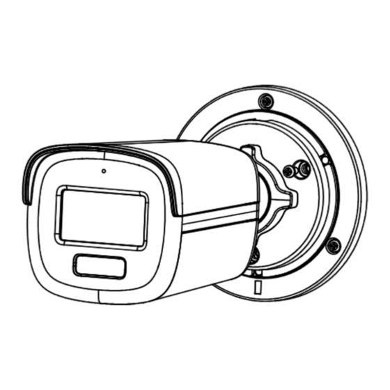
1.2.3 Overview of Type III Camera Enclosure Microphone Main Body Base Switch Button Power Cord Video Cable Installation Plate Figure 1-3 Overview of Type III Camera Notes: Press and hold the switch button for 5 seconds to switch the video output. Four kinds of video outputs are available: TVI, AHD, CVI, and CVBS 1.2.4 Overview of Type IV Camera Base... - Page 9 If the product does not function properly, contact your dealer or the nearest service center. DO NOT disassemble the camera for repair or maintenance by yourself. Installation of Type I and Type II Camera Before you start: The installation of type I and type II camera are similar. Following guide takes type I as example.
- Page 10 Figure 2-3 Fix the Camera to the Junction Box Cover 6. Secure the junction box body on the wall with three PA4 × 25 screws (supplied). Figure 2-4 Secure the Junction Box on the Wall 7. Route the cables through the bottom cable hole or side cable hole of the junction box and connect the cables.
- Page 11 Figure 2-7 Dissemble the Camera iii. Secure the base to the ceiling with three PA4 × 25 screws (supplied). iv. Align the screw hole with the triangle mark to install the camera back to the base and secure it. Triangle Mark Figure 2-8 Install the Camera to Ceiling 4.
- Page 12 Junction Box Cover Installation Plate PA4 × 10 Figure 2-10 Fix the Camera to the Junction Box For Type IV and Type V camera: PA4 × 25 PM3 × 13 Junction Box Cover M4 × 10 Installation Plate/Base Figure 2-11 Fix the Camera to the Junction Box 7.
-
Page 13: Menu Description
Figure 2-13 Fix the Installation Plate For Type IV camera: i. Refer to Step 3 of Section 2.2.1 to dissemble the camera ii. Use M4 × 10 screws to fix the base onto the wall mount. Figure 2-14 Fix the Base 4. -
Page 14: Video Format
VIDEO FORMAT EXPOSURE MODE ANTI-BANDING EXPOSURE BACK EXIT SAVE & EXIT LIGHTING MODE IR/WHITE LIGHT SMART IR THRESHOLD LIGHTING SETTINGS Level BACK EXIT SAVE & EXIT IMAGE MODE WHITE BALANCE BRIGHTNESS CONTRAST VIDEO MAIN MENU SHARPNESS SETTINGS SATURATION BACK EXIT SAVE &... - Page 15 4 MP@30 fps 4 MP@25 fps 4 MP@30 fps CVBS NTSC 3.2 EXPOSURE EXPOSURE MODE You can set the EXPOSURE MODE to GLOBAL, BLC, HLC, WDR, or HLS. GLOBAL GLOBAL refers to the normal exposure mode which adjusts lighting distribution, variations, and non-standard processing.
-
Page 16: White Light
N D Threshold (Night to Day Threshold) Night to Day Threshold is used to control the sensitivity of switching the night mode to the day mode. You can set the value from 1 to 9. The larger the value is, the more sensitive the camera is. -
Page 17: Audio Settings
BRIGHTNESS Brightness refers to the brightness of the image. You can set the brightness value from 1 to 9 to darken or brighten the image. The greater the value is, the brighter the image is. CONTRAST This feature enhances the difference in color and light between parts of an image.
Need help?
Do you have a question about the DS-2CE12KF0T-LFS and is the answer not in the manual?
Questions and answers