Table of Contents
Advertisement
Quick Links
Advertisement
Table of Contents

Related Manuals for TYAN GC70-B8033


Summary of Contents for TYAN GC70-B8033
- Page 1 GC70-B8033 Service Engineer’s Manual http://www.tyan.com...
- Page 2 MITAC assumes no liability whatsoever, and ® disclaims any express or implied warranty, relating to sale and/or use of TYAN products including liability or warranties relating to fitness for a particular purpose or merchantability. MITAC retains the right to make changes to produce descriptions and/or specifications at any time, without notice.
- Page 3 This Class A digital apparatus complies with Canadian ICES-003. Cet appareil numérique de la Classe A est conforme à la norme NMB-003 du Canada. Notice for Europe (CE Mark) ● This product is in conformity with the Council Directive 2014/30/EU and 2014/35/EU. http://www.tyan.com...
- Page 4 Replace only with the same or equivalent type recommended by manufacturer. Dispose of used battery according to manufacturer instructions and in accordance with your local regulations. Safety: UL/IEC/EN 62368-1 ● This equipment is compliant with UL/CB/LVD of Safety: UL/IEC/EN 62368-1. http://www.tyan.com...
- Page 5 This manual is intended for skilled person with hardware knowledge of computers. Components inside the compartments should be serviced only by a skilled person. This manual is aimed to provide you with instructions on installing your TYAN GC70-B8033. How this guide is organized...
- Page 6 Safety and Compliance Information Before installing and using TYAN GC70-B8033, take note of the following precautions: ·Read all instructions carefully. ·Do not place the unit on an unstable surface, cart, or stand. ·Do not block the slots and opening on the unit, which are provided for ventilation.
- Page 7 You must become familiar with the safety information in this guide before you install, operate, or service TYAN products. Symbols on Equipment Caution.
- Page 8 · Do not attempt to move a fully loaded rack. Remove equipment from the rack before moving it. · Do not attempt to move a rack on an incline that is greater than 10 degrees from the horizontal. http://www.tyan.com...
- Page 9 This will reduce the risk of personal injury, fire, or damage to the equipment. The total rack load should not exceed 80 percent of the branch circuit rating. Consult the electrical authority having jurisdiction over your facility wiring and installation requirements. http://www.tyan.com...
- Page 10 TYAN, your authorized TYAN partner, or their agents. Equipment Modifications · Do not make mechanical modifications to the system. TYAN is not responsible for the regulatory compliance of TYAN equipment that has been http://www.tyan.com...
- Page 11 – The product does not operate normally when you follow the operating instructions. · Retain all screws or other fasteners when removing access cover(s). Upon completion of accessing inside the product, refasten access cover with original screws or fasteners. http://www.tyan.com...
- Page 12 http://www.tyan.com...
-
Page 13: Table Of Contents
Table of Contents Chapter 1: Overview............... 17 About the TYAN GC70-B8033 ..........17 Product Models ............... 18 Features .................. 19 About the Product ..............24 1.4.1 System Front View ............24 1.4.2 System Rear View ............26 ... - Page 14 5.3.20 PCIe Slot Configuration ..........136 5.3.21 Redfish Host Interface Settings ........137 Chipset .................. 138 5.4.1 North Bridge Configuration ..........139 AMD CBS ................141 5.5.2 DF Common Options ..........146 http://www.tyan.com...
- Page 15 Chapter 6: Diagnostics ..............189 Flash Utility ................189 AMIBIOS Post Code (Aptio) ..........190 Appendix I: How to recover UEFI BIOS ........197 Appendix II: Cable Connection Tables ........199 Appendix III: Technical Support ..........201 http://www.tyan.com...
- Page 16 http://www.tyan.com...
-
Page 17: Chapter 1: Overview
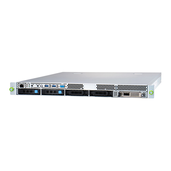
GC70-B8033 (B8033G70E2HR-CB) supports (2) 2.5" NVMe U.2 devices and Chicony 800W CRPS power supply type. The GC70-B8033 uses TYAN’s latest chassis featuring a robust structure and a solid mechanical enclosure. All of this provides GC70-B8033 the power and flexibility to meet the needs of nowadays server applications. http://www.tyan.com... -
Page 18: Product Models
Product Models The system board within the Tyan Barebone is defined by the following models: B8033G70E2HR-DB Single-socket AMD EPYC 7003 barenone platform with (2) 2.5” NVMe U.2 SSDs and (1) 22110/2280 M.2 connector by PCIe Gen4 interface, RPSU power supply type, Delta 800 Watts B8033G70E2HR-CB ... -
Page 19: Features
Features GC70-B8033 (B8033G70E2HR-CB) Form Factor 1U Rackmount Chassis Model GC70 Dimension (D x 27.4" x 17.32" x 1.7" (697 x 440 x 43.2mm) W x H) Motherboard S8033GME # System Name Motherboard # The motherboard not sold separately Notification Board 16"... - Page 20 10° C ~ 35° C (50° F~ 95° F) Temp. Operating Environment Non-operating - 40° C ~ 70° C (-40° F ~ 158° F) Temp. Barebone (20) GC70-B8033 Barebone Package Manual (20) Quick Installation Guide on Top Cover Contains Others Separately orderable items: 1U quick-released sliding rail http://www.tyan.com...
- Page 21 RoHS 6/6 RoHS Compliant GC70-B8033 (B8033G70E2HR-DB) Form Factor 1U Rackmount Chassis Model GC70 Dimension (D x 27.4" x 17.32" x 1.7" (697 x 440 x 43.2mm) W x H) Motherboard S8033GME # System Name Motherboard # The motherboard not sold separately...
- Page 22 Please refer to our AVL support lists. System list FCC (SDoC) Class A Regulation CE (DoC) Class A Operating 10° C ~ 35° C (50° F~ 95° F) Temp. Operating Environment Non-operating - 40° C ~ 70° C (-40° F ~ 158° F) Temp. http://www.tyan.com...
- Page 23 Barebone (20) GC70-B8033 Barebone Package Manual (20) Quick Installation Guide on Top Cover Contains Others Separately orderable items: 1U quick-released sliding rail RoHS 6/6 RoHS Compliant NOTE: 1. The specifications are subject to change without prior notice. 2. Please visit our Web site for the latest specifications.
-
Page 24: About The Product
BMC Health LED pre-installed) Drive Trays UID Button OCP 3.0 Mezz Tray Reset Button 1000Base-T dedicated Power Button w/LED MGMT LAN Port System Event LED USB3.2 Gen1 Port 2 PSU Status LED USB3.2 Gen1 Port 1 UID LED VGA Port http://www.tyan.com... - Page 25 Status LED (Red) Drive present, no activity Green Solid On Drive present with activity Green Blinking Drive Fail Don’t care Red Solid On Drive identify Don’t care Red Blinking @ 1Hz Drive Rebuild Don’t care Red Blinking @ 4Hz http://www.tyan.com...
-
Page 26: System Rear View
Description Description SYS_FAN_1 SYS_FAN_1 SYS_FAN_2 SYS_FAN_2 SYS_FAN_3 SYS_FAN_3 PSU1 M8033G70-PDB (pre-installed) PSU2 SYS_FAN_4 SYS_FAN_4 SYS_FAN_5 SYS_FAN_5 SYS_FAN_6 (reserved) SYS_FAN_6 (reserved) ID LED ID LED Rear Panel LED Indication Color Behavior ID LED Blue Remote located / Blue Sold On http://www.tyan.com... -
Page 27: Psu And Lan Led Indications
Green Solid On Green Solid On 100 Mbps Active Green Blinking Green Solid On Link Green Solid On Amber Solid On 1000 Mbps (1Gbps) Active Green Blinking Amber Solid On NOTE: “Left” and “Right” are viewed from the rear panel. http://www.tyan.com... -
Page 28: System Top View
1.4.4 System Top View CRPS SKU Description Description M1726G70-FPB System Fans (pre-installed) PSU1 Drive Trays OCP 3.0 Mezz Tray PSU2 S8033 Mainboard (pre-installed) http://www.tyan.com... - Page 29 PDB SKU Description Description M1726G70-FPB System Fans (pre-installed) M8033G70-PDB (pre-installed) Drive Trays OCP 3.0 Mezz Tray S8033 Mainboard (pre-installed) http://www.tyan.com...
-
Page 30: System Configuration
1.4.5 System Configuration CRPS SKU http://www.tyan.com... - Page 31 PDB SKU http://www.tyan.com...
- Page 32 NOTE http://www.tyan.com...
-
Page 33: Chapter 2: Setting Up
Caution! To avoid damaging the motherboard and associated components, use torque force within the range kgf/cm (4.35 ~ 6.09 lb/in) on each mounting screw for motherboard installation. Do not apply power to the board if it has been damaged. http://www.tyan.com... -
Page 34: Precautions
Working on a system that is connected to a power supply can be extremely dangerous. Follow the guidelines below to avoid damage to GC70-B8033 or injury to yourself. Ground yourself properly before removing the top cover of the system. -
Page 35: Installing Motherboard Components
This section describes how to install components on to the motherboard, including CPUs, memory modules and Add-on cards. 2.1.1 Removing the Chassis Cover Follow these instructions to remove the GC70-B8033 chassis cover. 1. Use a screw driver to loosen the thumb screw. 2. Slide to lift up the top cover. http://www.tyan.com... -
Page 36: Replacing The Chassis Cover
2.1.2 Replacing the Chassis Cover Follow these instructions to replace the GC70-B8033 chassis cover. Place the top cover on the chassis and slide it forwards. Use a screw driver to fasten the thumb screw. http://www.tyan.com... -
Page 37: Installing The Cpu And Heat Sink
2.1.3 Installing the CPU and Heat sink Follow the steps below on installing CPU and CPU heat sink. The GC70-B8033 supports single AMD Socket SP3. The following installation is based on an AMD Socket SP3. 1. Use a T20 Torx screwdriver to loosen the screws securing the force frame in a sequential order (3->2->1). - Page 38 During installation, observe the following: 1. Make sure to push the carrier frame with package towards the end of the rail frame until it clicks into place. 2. Do not drop the carrier frame or touch the package pad to avoid component damage. http://www.tyan.com...
- Page 39 6. Close the force frame. Then use a T20 Torx screwdriver to tighten the screws to secure the force frame in a sequential order (1 ->2->3). 7. Place a heatsink on top of the processor. Use a T20 Torx screwdriver to tighten four screws in a diagonal sequence to secure the heat sink. http://www.tyan.com...
-
Page 40: Installing The Air Duct
Installing the Air Duct Follow these instructions to install the air duct. 1. Take out the air duct. 2. Align the guide pins on the air duct with the guide pins on the chassis. 3. Place the air duct onto the chassis. http://www.tyan.com... -
Page 41: Installing The Memory
Press the memory slot locking levers in the direction of the arrows as shown in the following illustration. Align the memory module with the slot. When inserted properly, the memory slot locking levers lock automatically onto the indentations at the ends of the module. http://www.tyan.com... - Page 42 Memory Population table http://www.tyan.com...
- Page 43 http://www.tyan.com...
-
Page 44: Installing The 2.5" Hard Drive
Installing the 2.5” Hard Drive Follow these instructions to install the 2.5” SSD/NVMe drives. 1. Press the locking tab to pull the lever open. 2. Slide the drive tray out. 3. Press the locking tab to pull the tray side rail open. http://www.tyan.com... - Page 45 4. Align the hard drive with the guide pins and install the hard drive into the drive tray. Close the tray side rail. 5. Insert the drive tray into the chassis and close the lever. http://www.tyan.com...
-
Page 46: Installing The M.2 Card
Installing the M.2 Card Follow these instructions to install the M.2 Card. 1. The M.2 Latch is pre-installed on the mainboard. 2. Insert the M.2 card into the slot. 3. Pull the M.2 Latch to lock the M.2 card in place. http://www.tyan.com... -
Page 47: Installing The Ocp Mezz Card
Follow these instructions to install the OCP Mezz Card. 1. Take out the OCP Mezz card. 2. Insert and slide the OCP Mezz card all the way into the chassis until it clicks. 3. Use a screw driver to fasten the thumb screw. http://www.tyan.com... -
Page 48: Installing The Gpu Card
Follow these instructions to install the GPU Card. 1. Take out the GPU Bracket. 2. Insert the GPU card into the GPU bracket. Use a screw driver to secure three screws. 3. Align the GPU Bracket with the guide pins on the chassis. http://www.tyan.com... - Page 49 4. Use a screw driver to fasten the thumb screws. Finally connect the GPU PWR cable. http://www.tyan.com...
- Page 50 NOTE http://www.tyan.com...
-
Page 51: Chapter 3: Replacing Pre-Installed Components
This chapter explains how to replace the pre-installed components, including the S8033 Motherboard, M1726G70-FPB Front Panel Board, M8033G70-L16-1F Riser Card, M8033G70-PDB Power Distribution Board, System Fan and Power Supply etc. Disassembly Flowchart The following flowchart outlines the disassembly procedure. http://www.tyan.com... -
Page 52: Removing The Cover
Removing the Cover Follow Chapter 2.1.1 to remove the cover of GC70-B8033. Replacing the Power Supply To replace the power supply follow these instructions. Press the latch as shown to pull out the power supply module. Replace a new single power and reinsert it into the power cage following the above steps in reverse. -
Page 53: Replacing The Front Panel Board
2. Use a screw driver to loosen the thumb screw and push the front panel board backwards to lift it up. 3. After replacing with a new Front Panel Board, follow the steps described earlier in reverse order to reinstall the front panel bezel. http://www.tyan.com... -
Page 54: Front Panel Board Features
Connector Definitions Location Definition RJ45 LAN (management port) FP USB Header J4/J5 Type-A USB3.2 Gen1 Port System Alert (top) / PWROK LED (bottom) UID LED (top) / BMC Health LED (bottom) UID Button Reset Button PWR Button w/LED FPIO Connector http://www.tyan.com... -
Page 55: Replacing Power Distribution Board
1. Disconnect the power cable from the Power Distribution Board. Use a screw driver to loosen the thumb screw and then push the PDB forwards to unlock. 2. After replacing with a new PDB, follow the steps described earlier in reverse order to reinstall the power distribution board into the chassis. http://www.tyan.com... -
Page 56: Power Distribution Board Features
M8033G70-PDB Power Distribution Board Form Factor D71.5 x W140 mm, 6-layer PCB, thickness: 1.62mm It is a conversion board from 48Vdc Busbar clip to CRPS (common redundant power supply) connection. Connectors (1) PWRBP Connector (J1) (1) CRPS 50-pin Gold Finger (GF1) http://www.tyan.com... -
Page 57: Replacing The Riser Card
Riser Card. 1. Lift up the Riser Card Bracket from the chassis. Unscrew to replace with a new riser card M8033G70-L16-1F. 2. Follow the steps described earlier in reverse order to reinstall the riser card bracket into the chassis. http://www.tyan.com... -
Page 58: Riser Card Features
3.7.1 Riser card Features M8033G70-L16-1F Riser Card Form Factor 123 x 32mm, 6-layer PCB, thickness=1.57 mm (1) PCI-e x16 Gen3 Slot connector (SLOT1) Connectors (1) PCI-e x16 Gen3 Gold Finger connector (GF1) http://www.tyan.com... -
Page 59: Replacing The Fan
1. Disconnect the fan cable to lift up the fan module from the chassis. 2. Release the rubber screws from the fan module. Replace with a new fan and then insert the rubber screws. 4. Place the new fan module into the chassis and reconnect the fan cable. http://www.tyan.com... -
Page 60: Replacing The Motherboard
Replacing the Motherboard After removing all of the aforementioned components, follow these instructions to remove the motherboard from the chassis. Disconnect all MB cables. Unscrew the motherboard to lift it up for replacement. http://www.tyan.com... -
Page 61: Chapter 4: Mainboard Information
To avoid damaging the motherboard and associated components, do not use torque force greater than kgf/cm (4.35 ~ 6.09 lb/in) on each mounting screw for motherboard installation. Do not apply power to the board if it has been damaged. http://www.tyan.com... -
Page 62: Board Image
Board Image S8033 This picture is representative of the latest board revision available at the time of publishing. The board you receive may not look exactly like the above picture. http://www.tyan.com... -
Page 63: Block Diagram
Block Diagram S8033 http://www.tyan.com... -
Page 64: Mainboard Mechanical Drawing
Mainboard Mechanical Drawing http://www.tyan.com... -
Page 65: Board Parts, Jumpers And Connectors
The board you receive may not look exactly like the above diagram. But for the DIMM number please refer to the above placement for memory installation. For the latest board revision, please visit our web site at http://www.tyan.com. http://www.tyan.com... - Page 66 http://www.tyan.com...
- Page 67 +12Vstby AMBAlert# CR_BUS Return sense ISHARE +12V Remote sense PRESENT PWOK VIN_GOOD PW2: PCIe Power Connector Signal Signal +12V +12V +12V +12V +12V +12V +12V +12V GND2 GND1 J1/J2/J3/J4/J6/J7/J8: FAN Connector Signal Signal PRESENT PRESENT +12V +12V TACHOMETER TACHOMETER http://www.tyan.com...
- Page 68 TX_P2 TX_N2 RX_N2 RX_P2 TX_P3 RX_N3 TX_N3 RX_P3 TX_P4 TX_N4 RX_N4 RX_P4 TX_P5 TX_N5 RX_N5 RX_P5 TX_P6 RX_N6 TX_N6 RX_P6 RESET# WAKE# TX_P7 TX_N7 RX_N7 RX_P7 TX_P8 TX_N8 RX_N8 RX_P8 TX_P9 RX_N9 TX_N9 RX_P9 TX_P10 TX_N10 RX_N10 RX_P10 TX_P11 http://www.tyan.com...
- Page 69 TX_P14 TX_N14 RX_N14 RX_P14 TX_P15 TX_N15 RX_N15 RX_P15 REFCLK_P REFCLK_N PRESENT RESERVED HDT1: HDT Header Signal Signal CPU_VDDIO CPU_TCK CPU_TMS CPU_TDI CPU_TDO GNCPU_TRST# CPU_PWROK CPU_RST# CPU_DBREQ# CPU_VDDIO JTAG1: FPGA JTAG Header Signal Signal JTAG_TCK JTAG_TDO +3.3Vaux JTAG_TMS JTAG_TDI JTAG_HDR# http://www.tyan.com...
- Page 70 U2_1/U2_2/U2_3/U2_4: U.2 Connector Signal Signal REFCLK_P REFCLK_N TX_N15 TX_P15 RX_P15 RX_N15 +3.3Vaux RESET# WAKE# IFDET# TX_N14 TX_P14 RX_P14 PRESENT# RX_N14 RDYLED# TX_N13 +12V TX_P13 +12V +12V RX_P13 GND1 RX_N13 GND2 TX_N12 TX_P12 RX_P12 RX_N12 http://www.tyan.com...
- Page 71 SOUT J197/J193: BMC DEGUT SWITCH Header Signal Signal BMC_RXD5 (J197) RXD_OUT (J197) BMC_TXD5 (J193) TXD_OUT (J193) CPU_RX (J197) CPU_TX (J193) PIN1-2 CLOSED: BMC COM PORT (DEFAULT) PIN2-3 CLOSED: CPU COM PORT J209: BMC DEGUT Header Signal Signal BMC_RXD5 BMC_TXD5 http://www.tyan.com...
- Page 72 USB_DN GND2 USB_DP USB_SSRXN USB_SSRXP USB_SSTXN USB_SSTXP USB3_FPIO1: FP USB Header Signal Signal VCC_USB USB_SSRXN1 VCC_USB USB_SSRXP1 USB_SSRXN2 USB_SSRXP2 USB_SSTXN1 USB_SSTXP1 USB_SSTXN2 USB_SSTXP2 USB_DN1 USB_DP1 USB_DN2 USB_DP2 VGA1: VGA Header Signal Signal VGA_R VGA_G VGA_B VGA_DAT VGA_HS VGA_CLK VGA_VS http://www.tyan.com...
- Page 73 +3.3Vaux +3.3Vaux +3.3Vaux +3.3Vaux +3.3Vaux +3.3Vaux BMC_HB_LED# +3.3Vaux SYS_AIR_INLET +3.3Vaux NMI_BTN# +3.3Vaux RST_BTN# +3.3Vaux PWR_BTN# +3.3Vaux ID_LED_BTN# FP_PW_LED+ ID_LED+ FP_PW_LED- ID_LED- PHY_LED_ACT- PHY_LED_ACT+ PHY_MDI0+ PHY_LED_1000 PHY_MDI0- PHY_LED_100 PHY_MDI1+ PSU_SMBUS_ALERT# PHY_MDI1- BMC_SYS_FAULT# PHY_MDI2+ PHY_MDI2- FP_SMB_DAT FP_SMB_CLK GND1 GND2 GND3 GND4 http://www.tyan.com...
- Page 74 RBT_CRS_DV +12V_EDGE +12V_EDGE +12V_EDGE +12V_EDGE +12V_EDGE +12V_EDGE SMCLK BIF0# SMDAT BIF1# SMRST# BIF2# PRSNTA# PERST0# PERST1# +3.3V_EDGE PRSNTB2# AUX_PWR_EN REFCLKn1 FEFCLKn0 REFCLKp1 REFCLKp0 PERn0 PETn0 PERp0 PETp0 PERn1 PETn1 PERp1 PETn1 PERn2 PETn2 PERp2 PETp2 PERn3 PETn3 PERp3 PETp3 http://www.tyan.com...
- Page 75 PRSNTB0# PERn8 PETn8 PERp8 PETp8 PERn9 PETn9 PERp9 PETp9 PERn10 PETn10 PERp10 PETp10 PERn11 PETn11 PERp11 PETp11 PERn12 PETn12 PERp12 PETp12 PERn13 PETn13 PERp13 PETp13 PERn14 PETn14 PERp14 PETp14 PERn15 PETn15 PERp15 PETp15 USB_DATn RFU1_N/C USB_DATp RFU2_N/C PWRBKO# PRSNTB3# http://www.tyan.com...
-
Page 76: Tips On Installing Motherboard In Chassis
Some chassis include plastic studs instead of metal. Although the plastic studs are usable, MITAC recommends using metal studs with screws that will fasten the motherboard more securely in place. Below is a chart detailing what the most common motherboard studs look like and how they should be installed. http://www.tyan.com... - Page 77 http://www.tyan.com...
-
Page 78: Installing The Memory
Installing the Memory Before installing memory, ensure that the memory you have is compatible with the motherboard and processor. Check the TYAN Web site at http://www.tyan.com details of the type of memory recommended for your motherboard. This platform supports (8)+(8) DDR4 slots RDIMM DDR4 3200 w/ECC up to 1,024GB (64GB*4) / LRDIMM DDR4 3200 ... - Page 79 http://www.tyan.com...
- Page 80 Follow these instructions to install memory modules into the S8033. Unlock the clips as shown in the illustration. Insert the memory module firmly into the socket by gently pressing down until it sits flush with the socket. Lock the clips to secure the memory module into place. http://www.tyan.com...
-
Page 81: Installing Add-In Cards
TIP: It’s a good practice to install add-in cards in a staggered manner rather than making them directly adjacent to each other. Doing so allows air to circulate within the chassis more easily, thus improving cooling for all installed devices. http://www.tyan.com... -
Page 82: Finishing Up
In the rare circumstance that you have experienced difficulty, you can find help by asking your vendor for assistance. If they are not available for assistance, please find setup information and documentation online at our website or by calling your vendor’s support line. http://www.tyan.com... -
Page 83: Chapter 5: Bios Setup
The table below shows how to navigate in the setup program using the keyboard. Function Left/Right Arrow Keys Change from one menu to the next Up/Down Arrow Keys Move between selections Enter Open highlighted section PgUp/PgDn Keys Change pages Change options Exit http://www.tyan.com... -
Page 84: Getting Help
The following pages provide the details of BIOS menu. Please be noticed that the BIOS menu are continually changing due to the BIOS updating. The BIOS menu provided are the most updated ones when this manual is written. Please visit TYAN’s website at http://www.tyan.com for the information of BIOS updating. -
Page 85: Main Menu
System Date Set the Date. Use Tab to switch between Date elements. Default Ranges: Year: 1998~2999 Months: 1-12 Days: dependent on month Range of Years may vary. System Time Set the Time. Use Tab to switch between Time elements. http://www.tyan.com... -
Page 86: Advanced Menu
Configure the iSCSI parameters. VLAN Configuration (MAC: XXXXXXXXXXXX) VLAN Configuration (MAC: XXXXXXXXXXXX) MAC: XXXXXXXXXXXX --- IPV4 Network Configuration Configure network parameters. (MAC: XXXXXXXXXXXX) MAC: XXXXXXXXXXXX --- IPV6 Network Configuration Configure IPV6 network parameters. (MAC: XXXXXXXXXXXX) Network Stack Configuration Network Stack Settings. http://www.tyan.com... - Page 87 CPU Configuration Parameters. NVMe Configuration NVMe Devices Information. Trusted Computing Trusted Computing Settings. PCI Subsystem Settings PCI, PCI-X and PCI Express Settings. Option ROM Dispatch Policy Option ROM Dispatch Policy. PCIe Slot Configuration Redfish Host Interface Settings Redfish Host Interface Parameters. http://www.tyan.com...
-
Page 88: T1S Auth Configuration
5.3.1 T1s Auth Configuration Server CA Configuration Press <Enter> to configure Server CA. Client Cert Configuration Press <Enter> to configure Client Cert. http://www.tyan.com... - Page 89 5.3.1.1 Server CA Configuration Enroll Cert Press <Enter> to enroll cert. Delete Cert Press <Enter> to delete cert. http://www.tyan.com...
- Page 90 5.3.1.1.1 Enroll Cert Enroll Cert Using File Enroll Cert Using File. Cert GUID Input digit character in 11111111-2222-3333-4444-1234567890ab format. Commit Changes and Exit Commit Changes and Exit. Discard Changes and Exit Discard Changes and Exit. http://www.tyan.com...
- Page 91 5.3.1.1.2 Delete Cert XXXXX GUID for CERT. Disabled / Enabled http://www.tyan.com...
-
Page 92: Iscsi Configuration
Step 3. Save changes and reboot. Attempt Priority Change the priority using +/- keys. Use arrow keys to select the attempt then press +/- to move the attempt up/down in the attempt order list. Host iSCSI Configuration Host iSCSI Configuration. http://www.tyan.com... - Page 93 Change the priority using +/- keys. Use arrow keys to select the attempt then press +/- to move the attempt up/down in the attempt order list. Host Attempt / Redfish Attempt Commit Changes and Exit Commit Changes and Exit. http://www.tyan.com...
- Page 94 5.3.2.2 Host iSCSI Configuration iSCSI Initiator Name The worldwide unique name of iSCSI Initiator. Only IQN format is accepted. Enter [iqn.xxx]. xxx ranges from 4 to 223. For example: http://www.tyan.com...
- Page 95 Add an Attempt. Delete Attempts Delete one or more attempts. Change Attempt Order Change the order of Attempts using +/- keys. Use arrow keys to select the attempt then press +/- to move the attempt up/down in the attempt order list. http://www.tyan.com...
- Page 96 The screen shows the network protocols installed. If no network protocols are installed, the screen displays the message “Necessary network protocols are not available to retrieve….” MAC xx:xx:xx:xx:xx:xx (Intel® Ethernet Network Adapter) PFA: Bus 184 / Dev 0 / Func 0. http://www.tyan.com...
- Page 97 IPv4 / IPv6 / Autoconfigure Connection Retry Count The minimum value is 0 and the maximum is 16. 0 means no retry. Connection Establishing Timeout The timeout value in milliseconds. The minimum value is 100 milliseconds and the maximum is 20 seconds. http://www.tyan.com...
- Page 98 Hexadecimal representation of the LU number. Examples are: 4752-3A4F-6b7e-3F99, 6734-9-156f-127, 4186-9. Authentication Type Authentication method: CHAP, Kerberos, or None. CHAP / None Save Changes Must reboot system manually for changes to take place. Back to Previous Page Back to Previous Page. http://www.tyan.com...
- Page 99 5.3.2.2.2 Delete Attempts Commit Changes and Exit Commit Changes and Exit. Discard Changes and Exit Discard Changes and Exit. http://www.tyan.com...
- Page 100 5.3.2.2.3 Change Attempt Order Commit Changes and Exit Commit Changes and Exit. Discard Changes and Exit Discard Changes and Exit. http://www.tyan.com...
-
Page 101: Vlan Configuration (Mac:xxxxxxxxxxxx)
5.3.3 VLAN Configuration (MAC:xxxxxxxxxxxx) Enter Configuration Menu Press ENTER to enter configuration menu for VLAN configuration. http://www.tyan.com... - Page 102 Enter Configuration Menu VLAN ID VLAN ID of new VLAN or existing VLAN, valid value is 0~4094. Priority 802.1Q Priority, valid value is 0~7. Add VLAN Create a new VLAN or update existing VLAN. Remove VLAN Remove selected VLANs. http://www.tyan.com...
-
Page 103: Mac:xxxxxxxxxxxx - Ipv4 Network Configuration
5.3.4 MAC:xxxxxxxxxxxx - IPv4 Network Configuration Configured Indicate whether network address configured successfully or not. Disabled / Enabled Save Changes and Exit Save Changes and Exit. http://www.tyan.com... -
Page 104: Mac:xxxxxxxxxxxx - Ipv6 Network Configuration
5.3.5 MAC:xxxxxxxxxxxx - IPv6 Network Configuration Enter Configuration Menu Press ENTER to enter configuration menu for IPv6 configuration. http://www.tyan.com... - Page 105 Automatic / Manual NOTE: The Advanced Configuration submenu is available when Policy is set to [Manual]. Advanced Configuration Configure the interface manually. IP address, gateway address, and DNS server address can be configured. Save Changes and Exit Save Changes and Exit. http://www.tyan.com...
- Page 106 DNS addresses can only be configured under manual policy. e.g. 2002::4. Separate the IP address with blank space to configure more than one address. Commit Changes and Exit Commit Changes and Exit. Discard Changes and Exit Discard Changes and Exit. http://www.tyan.com...
-
Page 107: Network Stack Configuration
Enable Ipv4 HTTP Boot Support. If disabled IPV4 HTTP boot support will not be available. Disabled / Enabled Ipv6 PXE Support Enable Ipv6 PXE Boot Support. If disabled IPV6 PXE boot support will not be available. Disabled / Enabled http://www.tyan.com... - Page 108 Disabled / Enabled PXE boot wait time Wait time to press ESC key to abort the PXE boot. Media detect count Number of times the presence of media will be checked. Use either +/- or numeric keys to set the value. http://www.tyan.com...
-
Page 109: Acpi Settings
5.3.7 ACPI Settings Enable ACPI Auto Configuration Enables or Disables BIOS ACPI Auto Configuration. Disabled / Enabled http://www.tyan.com... -
Page 110: S5 Rtc Wake Settings
Select 0-23. For example enter 3 for 3am and 15 for 3pm. Wake up minute Select 0-59 for Minute. Wake up second Select 0-59 for Second. When Wake system from S5 is set to [Dynamic Time] Wake up Minute increase 1-5. http://www.tyan.com... -
Page 111: Serial Port Console Redirection
Console redirection enable or disable. Disabled / Enabled Legacy Console Redirection Settings Legacy Console redirection settings. Console Redirection Settings The settings specify how the host computer (which the user is using) will exchange data. Both computers should have the same or compatible settings. http://www.tyan.com... - Page 112 0 if the num of 1’s in the data bits is even. Odd: parity bit is 0 if the num of 1’s in the data bits is odd. Mark: parity bit is always 1. Space: parity bit is always 0. Mark and Space parity do not allow for error detection. None / Even / Odd / Mark / Space http://www.tyan.com...
- Page 113 On this mode enabled only text will be sent. This is to capture Terminal data. Disabled / Enabled Resolution 100x31 Enable or disable extended terminal resolution. Disabled / Enabled Putty KeyPad Select FunctionKey and KeyPad on Putty. VT100 / LINUX / XTERMR6 / SCO / ESCN / VT400 http://www.tyan.com...
- Page 114 When BootLoader is selected, then Legacy Console Redirection is disabled before booting to legacy OS, When Always Enable is selected, then Legacy Console Redirection is enabled for legacy OS. Default setting for this option is set to Always Enable. Always Enable / BootLoader http://www.tyan.com...
- Page 115 VT-UTF8 / VT100 / VT100+ / ANSI Bits per Second Select serial port transmission speed. The speed must be matched on the other side. Long or noisy lines may require lower speeds. 115200 / 9600 / 19200 / 57600 http://www.tyan.com...
- Page 116 ‘start’ signal can be sent to restart the flow. Hardware flow control uses two wires to send start/stop signal. None / Hardware RTS/CTS / Software Xon/Xoff Data Bits EMS / Parity EMS / Stop Bits EMS Read only. http://www.tyan.com...
-
Page 117: Usb Configuration
USB Mass Storage Driver Support Enable/Disable USB Mass Storage Driver Support. Disabled / Enabled Port 60/64 Emulation Enables I/O Port 60h/64h emulation support. This should be enabled for the complete USB keyboard legacy support for non-USB aware OSes. Disabled / Enabled http://www.tyan.com... - Page 118 Hub descriptor. Auto / Manual NOTE: Device power up delay in seconds is available when Device power-up delay is set to [Manual]. Device power-up delay in seconds Delay range is 1…40 seconds, in one second increments. http://www.tyan.com...
-
Page 119: Onboard Device Configuration
Onboard VGA Enable/Disable ASPEED VGA. Enabled / Disabled Active Video Select between onboard or external VGA support. Onboard / External NMI Function Enable or Disable NMI function. Enabled / Disabled Clock Spread Spectrum Enable/Disable Clock Spread Spectrum. Enabled / Disabled http://www.tyan.com... -
Page 120: Ast2500 Super Io Configuration
5.3.12 AST2500 Super IO Configuration Serial Port 1 Configuration Set Parameters of Serial Port 1 (COMA). http://www.tyan.com... - Page 121 Serial Port Enable or disable Serial Port (COM). Enabled / Disabled Device Settings Read only. Change Settings Select an optimal setting for Super IO Device. Auto ; / IO=3F8h; IRQ=4; / IO=2F8h, IRQ=4; / IO=3E8h, IRQ=4; / IO=2E8h, IRQ=4; http://www.tyan.com...
-
Page 122: Hardware Health Configuration
PWM Minimal Duty Cycle (%).This item is available when Fan Speed Control is set to [Manual]. BMC Alert Beep Enable/Disable BMC Alert Beep. On / Off PMBus support PMBus Support. Enabled / Disabled Number of PSU User can select PSU number for needed. 1 / 2 http://www.tyan.com... - Page 123 5.3.13.1 Sensor Data Register Monitoring http://www.tyan.com...
- Page 124 NOTE: SDR can not be modified. Read only. http://www.tyan.com...
-
Page 125: Csm Configuration
Network Controls the execution of UEFI and Legacy PXE OpROM UEFI / Legacy Storage Controls the execution of UEFI and Legacy Storage OpROM UEFI / Legacy Video Controls the execution of UEFI and Legacy Video OpROM UEFI / Legacy http://www.tyan.com... - Page 126 Other PCI devices Determines OpRom execution policy for devices other than network, storage, or video UEFI / Legacy http://www.tyan.com...
-
Page 127: Cpu Configuration
5.3.15 CPU Configuration SVM Mode Enable/disable CPU Virtualization. Enabled / Disabled SMEE Mode Control secure memory encryption enable. Enabled / Disabled CPU0 Information View Information related to CPU 0. http://www.tyan.com... - Page 128 5.3.15.1 CPU0 Information Read only. http://www.tyan.com...
-
Page 129: Nvme Configuration
5.3.16 NVMe Configuration If no NVME device is installed, it shows no NVME Device Found. If a NVME device is installed, this page shows the Device Name you installed as shown below. http://www.tyan.com... -
Page 130: Trusted Computing
SHA256 PCR Bank Enable or Disable SHA256 PCR Bank. Disabled / Enabled Pending operation Schedule an Operation for the Security Device. NOTE: Your Computer will reboot during restart in order to change State of Security Device. None / TPM Clear http://www.tyan.com... - Page 131 TPM 1.2 will restrict support to TPM 1.2 devices, TPM 2.0 will restrict support to TPM 2.0 devices, Auto will support both with the default set to TPM 2.0 devices if not found, TPM 1.2 devices will be enumerated. TPM 1.2 / TPM 2.0 / Auto http://www.tyan.com...
-
Page 132: Pci Subsystem Settings
Space (Only if System Supports 64 bit PCI Decoding). Enabled / Disabled SR-IOV Support If system has SR-IOV capable PCIe Devices, this option Enables or Disables Single Root IO Virtualization Support. Enabled / Disabled PCI Express Settings Change PCI Express Devices Settings. http://www.tyan.com... - Page 133 PCI Express Settings Max Payload Set Maximum Payload of PCI Express Device or allow System BIOS to select the value. Auto / 128 Bytes / 256 Bytes / 512 Bytes / 1024 Bytes / 2048 Bytes / 4096 Bytes http://www.tyan.com...
-
Page 134: Option Rom Dispatch Policy
5.3.19 Option ROM Dispatch Policy OCP1 Enable or Disable Option ROM execution for selected Slot. Disabled / Enabled MINIPCIE_1 Enable or Disable Option ROM execution for selected Slot. Disabled / Enabled http://www.tyan.com... - Page 135 http://www.tyan.com...
-
Page 136: Pcie Slot Configuration
Auto / GEN1 (2.5G T/s) / GEN2 (5 GT/s) / GEN3 (8 GT/s) / GEN4 (16 GT/s) MINIPCIE_1 Maximum Link Speed for MINIPCIE_1 slot. Auto / GEN1 (2.5G T/s) / GEN2 (5 GT/s) / GEN3 (8 GT/s) / GEN4 (16 GT/s) http://www.tyan.com... -
Page 137: Redfish Host Interface Settings
5.3.21 Redfish Host Interface Settings Redfish Enable/Disable AMI Redfish. Enabled / Disabled BMC Redfish Version / BIOS Redfish Version Read only. IP Address Enter IP address. IP Mask Address Enter IP Mask address. IP Port Enter IP Port. http://www.tyan.com... -
Page 138: Chipset
Chipset PCIe Compliance Mode PCIe Link Compliance Mode. Disabled / Enabled North Bridge North Bridge Parameters. http://www.tyan.com... -
Page 139: North Bridge Configuration
5.4.1 North Bridge Configuration Memory Information Total Memory: xxxxx MB CPU 0 Information View Memory Information related to CPU 0. http://www.tyan.com... - Page 140 5.4.1.1 CPU 0 Information Read only. http://www.tyan.com...
-
Page 141: Amd Cbs
AMD CBS CPU Common Options CPU Common Options. DF Common Options DF Common Options. UMC Common Options UMC Common Options. NBIO Common Options NBIO Common Options. FCH Common Options FCH Common Options. http://www.tyan.com... - Page 142 Enable/Disable PFEH, cloak individual banks, and mask deferred error interrupts from each bank. Enabled / Disabled / Auto Core Performance Boost Disable CPB. Disabled / Auto Global C-state Control Controls IO based C-state generation and DF C-states. Disabled / Enabled / Auto http://www.tyan.com...
- Page 143 When this option is enabled, specific uncorrected errors detected by the PSP FW or SMU FW will hang and not reset the system. Disabled / Enabled / Auto SNP Memory (RMP Table) Coverage Enabled=ENTIRE system memory is covered. Disabled / Enabled / Custom / Auto http://www.tyan.com...
- Page 144 Auto / ONE (1+0) / TWO (2+0) / THREE (3+0) / FOUR (4+0) / FIVE (5+0) / SIX (6+0) / SEVEN (7+0) SMT Control Can be used to disable symmetric multithreading. To re-enable SMT, a POWER CYCLE is needed after selecting the ‘Auto’ option. Disabled / Enabled / Auto http://www.tyan.com...
- Page 145 5.5.1.2 Prefetcher settings L1 Stream HW Prefetcher Option to Enable/Disable L1 Stream HW Prefetcher. Disabled / Enabled / Auto L2 Stream HW Prefetcher Option to Enable/Disable L2 Stream HW Prefetcher. Disabled / Enabled / Auto http://www.tyan.com...
-
Page 146: Df Common Options
PSP error injection support ‘True’ enables error injection. False / True RAS EINJ Mode BIOS: Send APEI EINJ actions to PSP via CPM EINJ SMI callback; PSP: Send APEI EINJ actions to PSP via PSP Mailbox. BIOS / PSP http://www.tyan.com... - Page 147 Disabled / 1 hour / 4 hours / 8 hours / 16 hours / 24 hours / 48 hours / Auto Poison scrubber control Poison scrubber control. Disabled / Enabled / NPS4 Redirect scrubber control Redirect scrubber control. Disabled / Enabled / Auto http://www.tyan.com...
- Page 148 1 Kbytes, 2 Kbytes and 4 Kbytes. This determines the starting address of the interleave (bit 8, 9, 10, 11 or 12). 256 Bytes / 512 Bytes / 1 KB / 2 KB / 4 KB / Auto http://www.tyan.com...
- Page 149 5.5.2.3 ACPI ACPI SRAT L3 Cache As NUMA Domain Enabled: Each CCX in the system will be declared as a separate NUMA domain. Disabled: Memory Addressing \ NUMA nodes per socket will be declared. Disabled / Enabled / Auto http://www.tyan.com...
- Page 150 5.5.3 UMC Common Options DDR4 Common Options DDR4 Common Options. DRAM Memory Mapping DRAM Memory Mapping. NVDIMM NVDIMM. http://www.tyan.com...
- Page 151 5.5.3.1 DDR4 Common Options DRAM Timing Configuration DRAM Timing Configuration. Common RAS Common RAS. Security Security. http://www.tyan.com...
- Page 152 5.5.3.1.1 DRAM Time Configuration Overclock Memory Overclock settings. Auto / Enabled Memory Clock Speed (available if Overclock is set to [Enabled]) Specifies the memory clock frequency. Auto / 2666MT/s / 2933MT/s / 3200MT/s http://www.tyan.com...
- Page 153 5.5.3.1.2 Common RAS Data Poisoning Enable/Disable data poisoning. Disabled / Enabled / Auto ECC Configuration ECC Configuration. http://www.tyan.com...
- Page 154 ECC Configuration DRAM ECC Symbol Size DRAM ECC Symbol Size (x4/x8/x16). x4 / x8 / x16 / Auto DRAM ECC Enable Use this option to enable/disable DRAM ECC. Auto will set ECC to enable. Disabled / Enabled / Auto http://www.tyan.com...
- Page 155 5.5.3.1.3 Security TSME Transparent Secure Memory Encryption. Auto / Disabled / Enabled Data Scramble Data Scrambling. Auto / Disabled / Enabled http://www.tyan.com...
- Page 156 5.5.3.2 DRAM Memory Mapping Chipselect Interleaving Interleave memory blocks across the DRAM chip selects for node 0. Disabled / Auto BankGroupSwap Bank Group Swap settings. Enabled / Disabled / Auto http://www.tyan.com...
- Page 157 5.5.3.3 NVDIMM NVDIMM-N Feature Disable NVDIMM-N feature for memory margin tool. Enabled / Disabled http://www.tyan.com...
- Page 158 Enables Alternative Routing-ID Interpretation. Disabled / Enabled / Auto PCIe Ten Bit Tag Support Enables PCIe ten bit tags for supported devices. Auto=Disable. Auto / Enabled / Disabled Preferred IO Preferred IO Select Type Auto: Default. Manual / Auto http://www.tyan.com...
- Page 159 Preferred IO Bus (available if Preferred IO is set to [Manual]) Preferred IO Bus Number 0x0-0xFF: Bus Number. SEV-SNP Support Enable or Disable SEV-SNP Support. Disabled / Enabled SMU Common Options SMU Common Options. NBIO RAS Common Options NBIO RAS Common Options. http://www.tyan.com...
- Page 160 Auto=Use default performance determinism settings. Power Performance Auto / Power / Performance cTDP Control Auto=Use the fused TDP Manual=User can set customized TDP Manual / Auto cTDP (available if cTDP Control is set to [Manual]) cTDP [W] 0 = Invalid value. http://www.tyan.com...
- Page 161 Collaborative Processor Performance/Power Control. Disabled / Enabled / Auto EfficiencyModeEn Auto=use performance optimized settings. Enabled=use power efficiency optimized settings. Auto / Enabled HSMP Support Select Host System Management Port support. Disabled / Enabled / Auto LCLK Frequency Control LCLK Frequency Control. http://www.tyan.com...
- Page 162 Set Root Complex LCLK Frequency (Bus range 0x80-0xBF). Auto=Dynamic Frequency Control. 593Mhz=Set LCLK Frequency at 593MHz. Auto / 593Mhz Root Complex 0xC0 LCLK Frequency Set Root Complex LCLK Frequency (Bus range 0xC0-0xFF). Auto=Dynamic Frequency Control. 593Mhz=Set LCLK Frequency at 593MHz. Auto / 593Mhz http://www.tyan.com...
- Page 163 NBIO SyncFlood Generation This value may be used to mask SyncFlood caused by NBIO RAS options. When set to TRUE SyncFlood from NBIO is masked. When set to FALSE NBIO is capable of generating SyncFlood. Enabled / Disabled / Auto http://www.tyan.com...
- Page 164 When this value is set to 0, write response errors will be logged in the MCA. When set to 1, write response errors will trigger an MCOMMIT error. Wheh this value is set to 2, write response errors are converted to Okay responses. Enabled / Trigger MCOMMIT Error / Log Errors in MCA http://www.tyan.com...
- Page 165 True. When ‘Sync Flood on PCIe Fatal Error’ is False, PcdAmdPcieSyncFloodOnFatal should be set to False. When ‘Sync Flood on PCIe Fatal Error’ is Auto, PcdAmdPcieSyncFloodOnFatal should retain its AGESA default. Auto / True / False http://www.tyan.com...
-
Page 166: Fch Common Options
5.5.5 FCH Common Options Ac Power Loss Options Ac Power Loss Options. FCH RAS Options FCH RAS Options. http://www.tyan.com... - Page 167 5.5.5.1 AC Power Loss Options AC Loss Control Select Restore AC Power Loss Method. Power Off / Power On / Last State http://www.tyan.com...
- Page 168 5.5.5.2 FCH RAS Options Reset after Sync flood Enable AB to forward downstream sync-flood message to system controller. Enabled / Disabled / Auto http://www.tyan.com...
-
Page 169: Server Management
3 minutes / 4 minutes / 5 minutes / 6 minutes FRB-2 Timer Policy Configure how the system should respond if the FRB-2 Timer expires. Not available if FRB-2 Timer is disabled. Do Nothing / Reset / Power Down / Power Cycle OS Watchdog Timer http://www.tyan.com... - Page 170 Enable or Disable BMC Logo. Enabled / Disabled System Event Log Press <Enter> to change the SEL event log configuration. BMC network configuration Configure BMC network parameters. BMC User Settings Press <Enter> to Add, Delete and Set Privilege level for users. http://www.tyan.com...
-
Page 171: System Event Log
No / Yes, on next reset / Yes, on every reset Log EFI Status Codes Disable the logging of EFI Status Codes or log only error code or only progress code or both. Disabled / Both / Error Code / Progress Code http://www.tyan.com... -
Page 172: Bmc Network Configuration
Enable or Disable LAN1 IPV6 Support. Enabled / Disabled Configuration Address Source Select the configure LAN channel parameters statically or dynamically (by BIOS or BMC). Unspecified option will not modify any BMC network parameters during BIOS phase. Unspecified / Static / DynamicBmcDhcp / DynamicBmcNonDhcp http://www.tyan.com... -
Page 173: Bmc User Settings
5.6.3 BMC User Settings Add User Press <Enter> to Add a user. Delete User Press <Enter> to Delete a user. Change User Settings Press <Enter> to change User Settings. http://www.tyan.com... - Page 174 User Access Enable/Disable the BMC User’s Access. Enabled / Disabled Channel No Enter BMC Channel Number. N/A / 1 / 8 User Privilege Limit Enter BMC User Privilege Limit for Selected Channel. None / User / Operator / Administrator http://www.tyan.com...
- Page 175 5.6.3.2 Delete User User Name Enter BMC User Name. User Password Enter New Password to change. Password at least 8 characters. http://www.tyan.com...
- Page 176 User Access Enable/Disable the BMC User’s Access. Enabled / Disabled Channel No Enter BMC Channel Number. N/A / 1 / 8 User Privilege Limit Enter BMC User Privilege Limit for Selected Channel. None / User / Operator / Administrator http://www.tyan.com...
-
Page 177: Security
Confirm New Password window will pop out to ask for confirmation. Secure Frozen Mode Enable or disable HDD security freeze lock. Disable to support secure erase function. For AHCI SATA ports only. Enabled / Disabled Secure Boot Secure Boot Configuration. http://www.tyan.com... -
Page 178: Secure Boot
Force System to User Mode. Install factory default Secure Boot key databases. Press ‘Yes’ to proceed ‘No’ to cancel. Reset to Setup Mode Delete all Secure Boot key database from NVRAM. Deleting all variables will reset the System to Setup Mode. Press ‘Yes’ to proceed ‘No’ to cancel. http://www.tyan.com... - Page 179 Key Management Enables expert users to modify Secure Boot Policy variables without full authentication. http://www.tyan.com...
- Page 180 Delete all Secure Boot key database from NVRAM. Deleting all variables will reset the System to Setup Mode. Press ‘Yes’ to proceed ‘No’ to cancel. Enroll Efi Image Allow the image to run in Secure Boot mode. Enroll SHA256 Hash certificate of a PE image into Authorized Signature Database (db). http://www.tyan.com...
- Page 181 Enroll Factory Defaults or load certificates from a file: 1. Public Key Certificate in: a) EFI_SIGNATURE_LIST b) EFI_CERT_X509 (DER) c) EFI_CERT_RSA2048 (bin) d) EFI_CERT_SHAXXX 2. Authenticated UEFI Variable 3. EFI PE/C0FF Image (SHA256) Key source: Factory, External, Mixed Update / Append http://www.tyan.com...
- Page 182 Enroll Factory Defaults or load certificates from a file: 1. Public Key Certificate in: a) EFI_SIGNATURE_LIST b) EFI_CERT_X509 (DER) c) EFI_CERT_RSA2048 (bin) d) EFI_CERT_SHAXXX 2. Authenticated UEFI Variable 3. EFI PE/C0FF Image (SHA256) Key source: Factory, External, Mixed Update / Append http://www.tyan.com...
-
Page 183: Boot
Quiet Boot Enable or disable Quiet Boot option. Enabled / Disabled Wait for ‘ESC’ If Error Wait for ‘ESC’ key to be pressed if error occurs. Enabled / Disabled Endless Boot Enable or disable Endless Boot. Enabled / Disabled http://www.tyan.com... - Page 184 Boot Option Priorities Boot Option #1 Select the system boot order. Device Name / Disabled Delete Boot Option Remove an EFI boot option from the boot order. http://www.tyan.com...
-
Page 185: Delete Boot Option
5.8.1 Delete Boot Option Delete Boot Option Remove an EFI boot option from the boot order. Select one to delete / Device Name http://www.tyan.com... -
Page 186: Save & Exit
Reset system setup without saving any changes. Save Changes Save changes done so far to any of the setup options. Discard Changes Discard changes done so far to any of the setup options. Restore Defaults Restore/Load Default values for all the setup options. http://www.tyan.com... - Page 187 Save as User Defaults Save the changes done so far as User Defaults. Restore User Defaults Restore the User Defaults to all the setup options. Boot Override Read only. http://www.tyan.com...
- Page 188 NOTE http://www.tyan.com...
-
Page 189: Chapter 6: Diagnostics
BIOS flash failure, you must contact your dealer for a replacement BIOS. There are no exceptions. TYAN does not have a policy for replacing BIOS chips directly with end users. In no event will TYAN be held responsible for damages done by the end user. -
Page 190: Amibios Post Code (Aptio)
South Bridge initialization before microcode loading 0x05 OEM initialization before microcode loading 0x06 Microcode loading 0x07 AP initialization after microcode loading 0x08 North Bridge initialization after microcode loading 0x09 South Bridge initialization after microcode loading 0x0A OEM initialization after microcode loading 0x0B Cache initialization http://www.tyan.com... - Page 191 CPU post-memory initialization is started 0x33 CPU post-memory initialization. Cache initialization 0x34 CPU post-memory initialization. Application Processor(s) (AP) initialization 0x35 CPU post-memory initialization. Boot Strap Processor (BSP) selection 0x36 CPU post-memory initialization. System Management Mode(SMM) initialization 0x37 Post-Memory North Bridge initialization is started http://www.tyan.com...
- Page 192 Reserved for future AMI progress codes S3 Resume Error Codes 0xE8 S3 Resume Failed 0xE9 S3 Resume PPI not Found 0xEA S3 Resume Boot Script Error 0xEB S3 OS Wake Error 0xEC – 0xEF Reserved for future AMI error codes http://www.tyan.com...
- Page 193 North Bridge DXE initialization (North Bridge module specific) 0x70 South Bridge DXE initialization is started 0x71 South Bridge DXE SMM initialization is started 0x72 South Bridge devices initialization 0x73 South Bridge DXE initialization (South Bridge module specific) 0x74 South Bridge DXE initialization (South Bridge module specific) http://www.tyan.com...
- Page 194 SCSI Enable 0xA8 Setup Verifying Password 0xA9 Start of Setup 0xAA Reserved for ASL (see ASL Status Codes section below) 0xAB Setup Input Wait 0xAC Reserved for ASL (see ASL Status Codes section below) 0xAD Ready To Boot event http://www.tyan.com...
- Page 195 System is entering S1 sleep state 0x02 System is entering S2 sleep state 0x03 System is entering S3 sleep state 0x04 System is entering S4 sleep state 0x05 System is entering S5 sleep state 0x10 System is waking up from the S1 sleep state http://www.tyan.com...
- Page 196 System is waking up from the S3 sleep state 0x40 System is waking up from the S4 sleep state 0xAC System has transitioned into ACPI mode. Interrupt controller is in PIC mode. 0xAA System has transitioned into ACPI mode. Interrupt controller is in APIC mode. http://www.tyan.com...
-
Page 197: Appendix I: How To Recover Uefi Bios
UEFI recovery bootloader that would prevent the recovery process itself from working. In no event shall Tyan be liable for direct, indirect, incidental, special or consequential damages arising from the BIOS update or recovery. - Page 198 “Flash update completed. Press any key to reset the system” displayed on screen. Remove the USB disk and reboot. If your system does not have video output or the POST code halts at “FF” on the right-lower portion of the screen, please contact Tyan representatives for RMA service. http://www.tyan.com...
-
Page 199: Appendix Ii: Cable Connection Tables
→ USB3_FPIO1 Cable 3. VGA Cable Chassis to S8033 (MB) Connect to S8033GME VGA Cable in front of Chassis → VGA1 4. LED Cable Chassis to S8033 (MB) Connect to S8033GME Rear plate of LED Cable → J208 Chassis http://www.tyan.com... - Page 200 NOTE http://www.tyan.com...
-
Page 201: Appendix Iii: Technical Support
MITAC serves multiple market segments with the industry’s most competitive services to support them. Please feel free to contact us directly for this service at tech-support@tyan.com Help Resources: 1. See the beep codes section of this manual. - Page 202 (RMA) number. The RMA number should be prominently displayed on the outside of the shipping carton and the package should be mailed prepaid. TYAN will pay to have the board shipped back to you. TYAN® GC70-B8033 Service Engineer’s Manual V1.0 Document No.: D2530-100...
Need help?
Do you have a question about the GC70-B8033 and is the answer not in the manual?
Questions and answers