
Related Manuals for Pickering 40-522


Summary of Contents for Pickering 40-522
- Page 1 40-522/523/524 User Manual PXI High Density Matrix Module pickeringtest.com Issue 7.4 February 2020...
- Page 2 © COPYRIGHT (2020) PICKERING INTERFACES. ALL RIGHTS RESERVED. No part of this publication may be reproduced, transmitted, transcribed, translated or stored in any form, or by any means without the written permission of Pickering Interfaces. Technical details contained within this publication are subject to change without notice.
- Page 3 Pickering Interfaces strives to fulfil all relevant environmental laws and regulations and reduce wastes and releases to the environment. Pickering Interfaces aims to design and operate products in a way that protects the environment and the health and safety of its employees, customers and the public. Pickering Interfaces endeavours to develop and manufacture products that can be produced, distributed, used and recycled, or disposed of, in a safe and environmentally friendly manner.
-
Page 4: Product Safety
If this product is heavy reference should be made to the safety instructions for provisions of lifting and moving. STATIC SENSITIVE To indicate that static sensitive devices are present and handling precautions should be followed. REED RELAY MODULE 40-110/115/120/125 HIGH DENSITY MATRIX MODULES 40-522/523/524 Page (IV) Page (IV) -
Page 5: Table Of Contents
Pre Operation Checks ............3.1 Hardware Installation ............3.2 Software Installation .............3.2 Testing Operation ..............3.3 Section 4 Programming Guide ..............4.1 Programming Options For Pickering PXI Modules ....4.1 Module Architecture ..............4.2 Using The IVI, Direct or VISA Driver ........4.3 Section 5 Connector Information ..............5.1 Section 6 Trouble Shooting .................6.1... - Page 6 THIS PAGE INTENTIONALLY BLANK HIGH DENSITY MATRIX MODULES 40-522/523/524 Page (VI)
-
Page 7: Warnings And Cautions
Not to be used in safety critical circuits, refer to the Pickering Interfaces’ terms & conditions of sale. This module must not be used for the switching of Mains Circuits. For the switching of voltages up to the module’s full specification, Secondary Circuit power supplies and the Device Under Test must... - Page 8 • For suitably equipped products in the event of an emergency press the red “emergency stop” button situated on the front of the unit. HIGH DENSITY MATRIX MODULES 40-522/523/524 Page (VIII) 2 AMP 1-POLE UHD MATRIX MODULES 40-575 / 576 / 577 / 578 / 579...
-
Page 9: Technical Specification
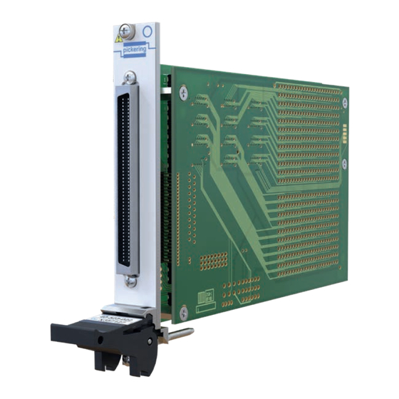
• Supported by PXI or LXI Chassis • Supported by eBIRST ™ • 3 Year Warranty The 40-522 module is configured as a dual 12x8 matrix and is available in 1-pole and 2-pole reed relay formats. Typical applications include signal routing in ATE and data acquisition systems. - Page 10 SECTION 1 - TECHNICAL SPECIFICATION Specifications pickering High Density Matrix – 40-522 Internal View of the 40-522 High Density Matrix Module Relay Type Mechanical Characteristics The 40-522 modules are fitted with ruthenium sputtered reed Single slot 3U PXI (CompactPCI card).
- Page 11 This product is supported by the eBIRST test tools which simplify the identification of failed relays, the required eBIRST tools are Product Customization below. For more information go to: pickeringtest.com/ebirst Pickering PXI modules are designed and manufactured on our own Product Test Tool Adaptor Termination...
- Page 12 44x4 2-Pole Matrix signals from multiple modules. However, for applications that • 40-524-021 46x4 1-Pole Matrix require a very large matrix, Pickering’s BRIC™ modules are best The screened version is suitable for switching coaxial signals up to suited. 50MHz. Supported by eBIRST...
- Page 13 Connectors with minimum downtime. PXI bus via 32-bit P1/J1 backplane connector. All reed relays are manufactured by our sister company Pickering Signals via front panel 96-pin male micro-D connector, for pin outs Electronics: pickeringrelay.com please refer to the operating manual.
- Page 14 40-523/524 93-002-001 93-002-226 93-016-103 Pickering PXI modules are designed and manufactured on our own Spare Relay Kits flexible manufacturing lines, giving complete product control and Kits of replacement relays are available for the majority of enabling simple customization to meet very specific requirements.
- Page 15 We provide a full range of supporting cable and connector solutions for all our switching products—20 connector families with 1200+ products. We offer everything from simple mating connectors to complex cables assemblies and terminal blocks. All assemblies are manufactured by Pickering and are guaranteed to mechanically and electrically mate to our modules. Connectors & Backshells...
- Page 16 High Density Matrix – 40-523/524 Programming Pickering provide kernel, IVI and VISA (NI & Keysight) drivers which are compatible with all Microsoft supported versions of Windows and popular older versions. For a list of all supporting operating systems, please see: pickeringtest.com/os...
-
Page 17: Functional Description
FUNCTIONAL DESCRIPTION A functional block diagram for the 40-522/523 is provided in Figure 2.1. The Matrix Module is powered by a +5V input via Compact PCI connector J1. The interface to the user test equipment is via the front panel mounted 96-pin micro-D connector, J2. - Page 18 RELAY CONTACTS RELAY COILS RELAY DRIVERS U10 TO U23 TERMINATING MODULE PCI BRIDGE RESISTORS CONFIGURATION R4 TO R15 U6, U7 AND U8 PCI BRIDGE CONFIGURATION Figure 2.2 - PXI Module 40-40-524: Functional Block Diagram HIGH DENSITY MATRIX MODULES 40-522/523/524 Page 2.2...
-
Page 19: Installation
Modular products require installation in a suitable PXI/LXI chassis. The module is designed for indoor use only. PREOPERATION CHECKS (UNPACKING) 1. Check the module for transport damage and report any damage immediately to Pickering Interfaces. Do not attempt to install the product if any damage is evident. -
Page 20: Hardware Installation
For a system comprising more than one chassis, turn ON the last chassis in the system followed by the penultimate, etc, and finally turn ON the external controller or chassis containing the system controller. 9. For Pickering Interfaces modular LXI installation there is no requirement to use any particular power up sequence. -
Page 21: Testing Operation
Figure 3.2 - General Soft Front Panel Icon A selector panel will appear, listing all installed Pickering PCI, PXI or LXI switch cards and resistor cards. Click on the card you wish to control, and a graphical control panel is presented allowing operation of the card. - Page 22 SECTION 3 - INSTALLATION pickering THIS PAGE INTENTIONALLY BLANK HIGH DENSITY MATRIX MODULES 40-522/523/524 Page 3.4...
-
Page 23: Programming Guide
SECTION 4 - PROGRAMMING GUIDE PROGRAMMING OPTIONS FOR PICKERING INTERFACES PXI CARDS For information on the installation and use of drivers and the programming of Pickering’s products in various software environments, please refer to the Software User Manual. This is available as a download from: https://www.pickeringtest.com/support/software-drivers-and-downloads... -
Page 24: Module Architecture
X and Y lines allowing single X-Y connections, or X-X connections using a Y line as a path. The 40-523 and 40-524 are single matrices controlled in the same way as the 40-522 but have matrix sizes of 44x4 1 or 2-pole and 46x4 1-pole respectively. - Page 25 Once the drivers are installed the manual “Sys40Prg.pdf” and driver help files which fully describes these functions can be found in the Pickering folder(s) or the Pickering entries on your Start Menu. The card must be opened before use and closed after using the following function calls: Direct I/O Driver - Open with PIL_OpenCards or PIL_OpenSpecifiedCard and close with PIL_CloseCards or PIL_CloseSpecifiedCards respectively.
- Page 26 SECTION 4 - PROGRAMMING GUIDE pickering THIS PAGE INTENTIONALLY BLANK HIGH DENSITY MATRIX MODULES 40-522/523/524 Page 4.4...
- Page 27 Y208 Y208.1 Y208.2 Y208.2 Y208 Y208.1 Y208 Y208 40-522-021 40-522-021 40-522-022 40-522-022 40-522-021-S 40-522-021-S Figure 5.1 - High Density Matrix Module 40-522: Connector Pinouts (96-pin Male Micro-D Connector Viewed From Front of Module) HIGH DENSITY MATRIX MODULES 40-522/523/524 Page 5.1...
- Page 28 X43.1 X44.2 X44.1 Y1.1 Y1.2 Y2.2 Y2.1 Y3.2 Y3.1 Y4.1 Y4.2 40-523-021 40-523-021-S 40-523-022 Figure 5.2 - High Density Matrix Module 40-523: Connector Pinouts (96-pin Male Micro-D Connector Viewed From Front of Module) HIGH DENSITY MATRIX MODULES 40-522/523/524 Page 5.2...
- Page 29 SECTION 5 - CONNECTOR INFORMATION pickering 40-524-021 Figure 5.3 - High Density Matrix Module 40-524: Connector Pinouts (96-pin Male Micro-D Connector Viewed From Front of Module) HIGH DENSITY MATRIX MODULES 40-522/523/524 Page 5.3...
- Page 30 SECTION 5 - CONNECTOR INFORMATION pickering THIS PAGE INTENTIONALLY BLANK HIGH DENSITY MATRIX MODULES 40-522/523/524 Page 5.4...
-
Page 31: Trouble Shooting
PCI configuration, highlighting any potential configuration problems. Specific details of all installed Pickering switch cards are included. All the installed Pickering switch cards should be listed in the “Pilpxi information” section - if one or more cards is missing it may be possible to determine the reason by referring to the PCI configuration dump contained in the report, but interpretation of this information is far from straightforward, and the best course is to contact Pickering support: support@pickeringtest.com, if possible... - Page 32 SECTION 6 - TROUBLE SHOOTING pickering THIS PAGE INTENTIONALLY BLANK HIGH DENSITY MATRIX MODULES 40-522/523/524 Page 6.2...
-
Page 33: Maintenance Information
For PXI modules which are supported in one of Pickering Interfaces’ Modular LXI Chassis (such as the 60-102B and 60-103B) no module software update is required. If the module was introduced after the LXI chassis was manufactured the module may not be recognized, in this case the chassis firmware may need upgrading. - Page 34 SECTION 7 - MAINTENANCE INFORMATION pickering RELAY LOOK-UP TABLES - 40-522 TABLE 7.1 - Dual 12 x 8 Matrix 40-522-021/022 Motherboard Relay Cross Reference 40-522 MOTHER BOARD - MATRIX 1 COLUMN A COLUMN B COLUMN C COLUMN D Relay No.
- Page 35 SECTION 7 - MAINTENANCE INFORMATION pickering TABLE 7.2 - Dual 12 x 8 Matrix 40-522-021/022 Daughterboard Relay Cross Reference 40-522 DAUGHTER BOARD - MATRIX 2 MOTHERBOARD COLUMN A COLUMN B COLUMN C COLUMN D 212r0 06/99 Relay No. Crosspoint Relay No.
-
Page 36: Relay Lookup Tables - 40-523
X21, Y2 X21, Y1 X22, Y4 X22, Y3 X22, Y2 X22, Y1 MOTHERBOARD 212r0 06/99 spare relays Figure 7.3 - 40-523-021/022 Motherboard Component Layout C102 C104 HIGH DENSITY MATRIX MODULES 40-522/523/524 Page 7.4 C101 C103 U112 U104 U108 C108 C112 C116... - Page 37 U108 C108 C112 C116 U111 U103 U107 C107 C111 C115 U110 U102 U106 C114 C106 C110 J101 U109 U105 U101 C105 C109 C113 DAUGHTERBOARD pickering J102 Figure 7.4 - 40-523-021/022 Daughterboard Component Layout HIGH DENSITY MATRIX MODULES 40-522/523/524 Page 7.5...
-
Page 38: Relay Lookup Tables - 40-524
X42, Y4 X43, Y1 X43, Y2 X43, Y3 X43, Y4 X44, Y1 X44, Y2 X44, Y3 X44, Y4 X45, Y1 X45, Y2 X45, Y3 X45, Y4 X46, Y1 X46, Y2 X46, Y3 X46, Y4 HIGH DENSITY MATRIX MODULES 40-522/523/524 Page 7.6... - Page 39 RL44 RL90 RL136 RL182 LK5 LK6 RL22 RL68 RL114 RL160 RL45 RL91 RL137 RL183 C D E SPARE SPARE RL23 RL69 RL115 RL161 RL46 RL92 RL138 RL184 Figure 7.5 - 40-524-021 Component Layout HIGH DENSITY MATRIX MODULES 40-522/523/524 Page 7.7...
- Page 40 SECTION 7 - MAINTENANCE INFORMATION pickering THIS PAGE INTENTIONALLY BLANK HIGH DENSITY MATRIX MODULES 40-522/523/524 Page 7.8...
Need help?
Do you have a question about the 40-522 and is the answer not in the manual?
Questions and answers