Table of Contents
Advertisement
Quick Links
This user's guide describes the operational use of the MLTLDO2EVM-037 evaluation module (EVM) as a
reference design for engineering demonstration and evaluation of linear regulators. The EVM is
specifically designed for linear regulators which are packaged in the DDA, DCY, 3-pin KVU and 5-pin KVU
packages. Included in this user's guide are setup and operating instructions, thermal and layout
guidelines, a printed circuit board (PCB) layout, a schematic diagram, and a bill of materials (BOM).
SBVU065 – May 2020
Submit Documentation Feedback
MLTLDO2EVM-037 Evaluation Module
Copyright © 2020, Texas Instruments Incorporated
User's Guide
SBVU065 – May 2020
MLTLDO2EVM-037 Evaluation Module
1
Advertisement
Table of Contents

Related Manuals for Texas Instruments MLTLDO2EVM-037


Summary of Contents for Texas Instruments MLTLDO2EVM-037
- Page 1 SBVU065 – May 2020 MLTLDO2EVM-037 Evaluation Module This user’s guide describes the operational use of the MLTLDO2EVM-037 evaluation module (EVM) as a reference design for engineering demonstration and evaluation of linear regulators. The EVM is specifically designed for linear regulators which are packaged in the DDA, DCY, 3-pin KVU and 5-pin KVU packages.
-
Page 2: Table Of Contents
Contents ...... General Texas Instruments High Voltage Evaluation (TI HV EVM) User Safety Guidelines ........................Introduction ......................... PCB Layout ........................Schematic ......................Bill of Materials List of Figures ......................Assembly Layer ......................Top Layer Routing ......................First Middle Layer ...................... - Page 3 Any other use and/or application are strictly prohibited by Texas Instruments. If you are not suitable qualified, you should immediately stop from further use of the HV EVM.
-
Page 4: Introduction
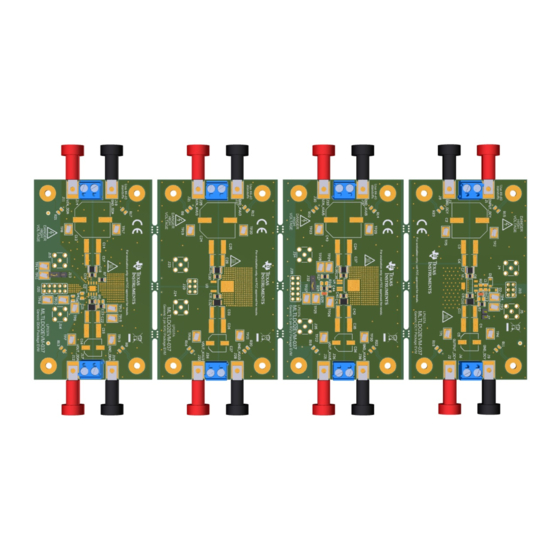
TI's MLTLDO2EVM-037 helps design engineers evaluate the operation and performance of linear regulators for possible use in their own circuit application. The MLTLDO2EVM-037 EVM offers four linear regulator designs, each one electrically isolated from the other through tab routing in the PCB fabrication step. - Page 5 The circuit module is not a finished product or electrical appliance. The module does not contain current or voltage thresholds for circuit protection. It must be used by qualified personnel with additional equipment for evaluation only. SBVU065 – May 2020 MLTLDO2EVM-037 Evaluation Module Submit Documentation Feedback Copyright © 2020, Texas Instruments Incorporated...
- Page 6 2.2.4 EVM System Grounding Each board within the MLTLDO2EVM-037 is electrically isolated from the other three boards in the EVM. External mounting holes are provided to mount the EVM to the system chassis. An 0805-sized surface pad is placed near each mounting hole. If populated, the components will tie the mounting hole to the internal board ground plane.
- Page 7 EVM Operation Beyond 50 Vdc (KVU|5 Package) or 100 Vdc (DCY, DDA, and KVU|3 Packages) If the end use of the MLTLDO2EVM-037 PCB will require larger voltages than it was designed for, it may still be possible to use it if the proper precautions are taken. A common method to extending the voltage rating of a PCB is to apply conformal coating.
- Page 8 DDA package EN pin header. Connect the jumper from pin 1 to pin 2 of the header to enable the DDA package linear regulator. 2.5.14 J14 – INPUT_DDA_TERMINAL Input voltage terminal block for the DDA package. MLTLDO2EVM-037 Evaluation Module SBVU065 – May 2020 Submit Documentation Feedback Copyright © 2020, Texas Instruments Incorporated...
- Page 9 Regulated output supply ground for the KVU 3-pin package. Use this connection for voltages at 50 Vdc or less. 2.5.29 J29 – KVU3 PACKAGE TEST HOOKUP Intended for test purposes only. SBVU065 – May 2020 MLTLDO2EVM-037 Evaluation Module Submit Documentation Feedback Copyright © 2020, Texas Instruments Incorporated...
- Page 10 DCY top bode resistor test point. 2.5.43 TP4 – DCY_BODE_BOTTOM DCY bottom bode resistor test point. 2.5.44 TP5 – DCY_INPUT_GND DCY input ground test point. MLTLDO2EVM-037 Evaluation Module SBVU065 – May 2020 Submit Documentation Feedback Copyright © 2020, Texas Instruments Incorporated...
- Page 11 A 3-pin KVU output test point. 2.5.58 TP19 – KVU3_INPUT A 3-pin KVU input test point. 2.5.59 TP20 – KVU3_INPUT_GND A 3-pin KVU input ground test point. SBVU065 – May 2020 MLTLDO2EVM-037 Evaluation Module Submit Documentation Feedback Copyright © 2020, Texas Instruments Incorporated...
- Page 12 Connect the equipment as shown in the following steps: 1. Review the data sheet for the linear regulator being installed on the MLTLDO2EVM-037 EVM. 2. Set the input power supply up to maximum rated voltage as listed on the data sheet, then turn it off.
-
Page 13: Pcb Layout
7. Disable the DDA package by connecting J13 pin 2 (EN_DDA) to J13 pin 3 (GND_DDA). PCB Layout Figure 1 Figure 5 illustrate the PCB layouts for this EVM. Figure 1. Assembly Layer Figure 2. Top Layer Routing SBVU065 – May 2020 MLTLDO2EVM-037 Evaluation Module Submit Documentation Feedback Copyright © 2020, Texas Instruments Incorporated... -
Page 14: First Middle Layer
PCB Layout www.ti.com Figure 3. First Middle Layer Figure 4. Second Middle Layer MLTLDO2EVM-037 Evaluation Module SBVU065 – May 2020 Submit Documentation Feedback Copyright © 2020, Texas Instruments Incorporated... -
Page 15: Bottom Layer Routing
PCB Layout www.ti.com Figure 5. Bottom Layer Routing SBVU065 – May 2020 MLTLDO2EVM-037 Evaluation Module Submit Documentation Feedback Copyright © 2020, Texas Instruments Incorporated... -
Page 16: Generic Dcy Package Schematic
100uF 47µF 47µF 100µF 100nF 100nF 10uF 100V 100nF 10.0k GND_DCY GND_DCY GND_DCY GND_DCY ADJ_DCY OUTPUT_DCY OUTPUT_DCY INPUT_DCY Figure 6. Generic DCY Package Schematic MLTLDO2EVM-037 Evaluation Module SBVU065 – May 2020 Submit Documentation Feedback Copyright © 2020, Texas Instruments Incorporated... -
Page 17: Schematic
1.0M TP13 TP14 TP15 TP16 TP17 GND_DDA GND_DDA GND_DDA GND_DDA VOUT_DDA VIN_DDA FB_NC_DDA EN_DDA DELAY_DDA PG_DDA Pin4_DDA GND_DDA Figure 7. Generic DDA Package Schematic SBVU065 – May 2020 MLTLDO2EVM-037 Evaluation Module Submit Documentation Feedback Copyright © 2020, Texas Instruments Incorporated... -
Page 18: Generic 3-Pin Kvu Package Schematic
100uF 47µF TPS7B8850QKVURQ1 47µF 100µF 100nF 100nF 10uF TP20 TP21 GND_KVU3 GND_KVU3 GND_KVU3 VIN_KVU3 GND_KVU3 VOUT_KVU3 GND_KVU3 Figure 8. Generic 3-pin KVU Package Schematic MLTLDO2EVM-037 Evaluation Module SBVU065 – May 2020 Submit Documentation Feedback Copyright © 2020, Texas Instruments Incorporated... - Page 19 10uF 100uF TP27 10nF TP28 10.0k 1.0M TP29 TP30 GND_KVU5 GND_KVU5 GND_KVU5 VOUT_KVU5 FB/NC_KVU5 EN_KVU5 VIN_KVU5 GND_KVU5 Figure 9. Generic 5-pin KVU Package Schematic SBVU065 – May 2020 MLTLDO2EVM-037 Evaluation Module Submit Documentation Feedback Copyright © 2020, Texas Instruments Incorporated...
-
Page 20: Bill Of Materials
These assemblies must comply with workmanship standards IPC-A-610 Class 2. Unless otherwise noted in the Alternate Part Number or Alternate Manufacturer columns, all parts can be substituted with equivalents. MLTLDO2EVM-037 Evaluation Module SBVU065 – May 2020 Submit Documentation Feedback Copyright © 2020, Texas Instruments Incorporated... - Page 21 Most LDOs in the DRV package SOIC8 Texas Instruments Most LDOs in the DQN package KVU0003A Texas Instruments Most LDOs in the SOT-23 package KVU0005A Texas Instruments SBVU065 – May 2020 MLTLDO2EVM-037 Evaluation Module Submit Documentation Feedback Copyright © 2020, Texas Instruments Incorporated...
- Page 22 TI products. TI’s provision of these resources does not expand or otherwise alter TI’s applicable warranties or warranty disclaimers for TI products. Mailing Address: Texas Instruments, Post Office Box 655303, Dallas, Texas 75265 Copyright © 2020, Texas Instruments Incorporated...
Need help?
Do you have a question about the MLTLDO2EVM-037 and is the answer not in the manual?
Questions and answers