Table of Contents
Advertisement
Quick Links
www.ti.com
EVM User's Guide: MCF8315RRYEVM
MCF8315 Evaluation Module
Description
The MCF8315RRYEVM allows users to evaluate
the performance of a MCF8315 motor driver. The
EVM includes an onboard FTDI chip to convert USB
communication, from the micro-USB connector, into
UART. An onboard MSP430FR2355 microcontroller
(MCU) translates the UART communication into
control signals, which is sent to the MCF8315 device.
There are many user-selectable jumpers, resistors,
connectors, and test points to assist with evaluating
the many features of the MCF8315 IC and the
configurable device-specific settings.
Get Started
1. Download the latest design files from the
MCF8315RRYEVM
tool page.
2. Download the latest version of the Motor Studio
GUI and firmware from the
page.
SLLU387 – AUGUST 2024
Submit Document Feedback
Motor Studio tool
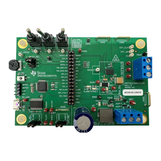
MCF8315RRYEVM (Top View)
Copyright © 2024 Texas Instruments Incorporated
Features
•
GUI software to simplify the MCx tuning process
and performance evaluation
•
MCU-to-MCx shunt jumper header with removable
shunts to disconnect main signals going to the
motor driver IC from the MCU
– The shunts can be removed if the user desires
to control the MCF8315 IC with an external
MCU or to use the EVM MCU to control an
external MCF8315 IC
Applications
•
Brushless-DC (BLDC) motor modules
•
Residential and living fans
•
Air purifiers and humidifier fans
•
Washer and dishwashers pumps
•
Automotive fan and blowers
•
CPAP machines
Description
MCF8315 Evaluation Module
1
Advertisement
Table of Contents

Related Manuals for Texas Instruments MCF8315


Summary of Contents for Texas Instruments MCF8315
- Page 1 IC from the MCU (MCU) translates the UART communication into – The shunts can be removed if the user desires control signals, which is sent to the MCF8315 device. to control the MCF8315 IC with an external There are many user-selectable jumpers, resistors,...
-
Page 2: Kit Contents
The MCF8315RRYEVM can support voltages up to 35V and currents up to 4A. To prevent damage to both the IC and the EVM, confirm that these voltage and current specifications are not exceeded. To check which MCF8315 chip is populated on the EVM by default by looking at the sticker label, see Figure 1-1 for the sticker label location, with the default part number of MCF8315 referenced. -
Page 3: Device Information
Evaluation Module Overview 1.4 Device Information The MCF8315 is a 4.5V to 35V, 4A peak integrated three-phase gate driver IC with code-free sensorless field-oriented control (FOC) for motor drive applications. The MCF8315 provides three accurately trimmed and temperature compensated half-bridge MOSFETS, gate drivers, charge pump, current sense amplifier, linear regulator for the external load and adjustable buck regulator. - Page 4 Optionally, use the GUI (as shown in Section 3) to monitor real-time speed of the motor, put the MCF8315 into a low-power sleep mode, and read status of the LEDs. Figure 2-1. Reference for Quick Start Guide MCF8315 Evaluation Module SLLU387 –...
-
Page 5: Hardware Setup
4.5V to 35V. The MCF8315 includes three integrated half-bridges and implements a sensorless FOC algorithm to spin a motor with up to 4A peak current. The MCF8315 also integrates an adjustable buck regulator. For interfacing with the GUI, the MCF8315RRYEVM has an onboard FTDI chip and MSP430. -
Page 6: Connection Details
5V_SEL jumper J3 and 3V3_SEL jumper J5 to connect external power rails. Figure 2-4. Micro-USB Connector and USB-to-UART interface MCF8315 Evaluation Module SLLU387 – AUGUST 2024 Submit Document Feedback Copyright © 2024 Texas Instruments Incorporated... -
Page 7: Led Lights
D7, can be used for debug purposes as well. The 32-pin shunt jumper bridge J6 ties all signals between the microcontroller and MCF8315 IC. These jumpers can be inserted or removed as needed to isolate the microcontroller from the gate driver. This allows for microcontroller signal debugging or using the MCF8315RRYEVM as a standalone gate driver with an external microcontroller. - Page 8 Name Color Description Internal buck regulator is voltage output Buck Regulator Green Lights up when fault condition has occurred on MCF8315 nFAULT Lights up when alarm condition has occurred on MCF8315 ALARM Motor power is supplied to the board Green...
-
Page 9: User-Configurable Settings
Turns on all low-side MOSFETs Right Brake disabled Left Controls direction of motor Right Left MCF8315 FETs disabled DRVOFF Disables gate drivers Right MCF8315 FETs enabled SLLU387 – AUGUST 2024 MCF8315 Evaluation Module Submit Document Feedback Copyright © 2024 Texas Instruments Incorporated... - Page 10 3.1 Firmware and GUI Application The MCF8315RRYEVM includes a USB-to-UART interface, using a MSP430FR2355 microcontroller, that serves as a communication bridge between a host PC and the MCF8315 device for configuring various device settings and reading fault diagnostic information. The MCF8315RRYEVM is supported on the Motor Studio GUI which can be used to configure the MCF8315 though this communication interface.
- Page 11 5. Select the folder created in Step 1 by extracting the Motor Studio firmware. 6. Import the project into your workspace as shown in Figure 3-2. Figure 3-2. MSP430FR2355 Interface Firmware Code in Code Composer Studio SLLU387 – AUGUST 2024 MCF8315 Evaluation Module Submit Document Feedback Copyright © 2024 Texas Instruments Incorporated...
- Page 12 MSP430 LaunchPad (eZ-FET Debug Probe Side) (J101) MCF8315RRYEVM 4-pin SPI-by-Wire Header (J4) 3.3V SBWTDIO SBWTDIO SBWTCK SBWTCK Figure 3-3. MSP430 LaunchPad eZ-FET Probe Connected to MCF8315RRYEVM MCF8315 Evaluation Module SLLU387 – AUGUST 2024 Submit Document Feedback Copyright © 2024 Texas Instruments Incorporated...
- Page 13 4.1.1 Main Supply and Pi Filter Figure 4-1. Main Supply and Pi Filter Schematic 4.1.2 Connectors and Interface Figure 4-2. Connectors and Interface Schematic SLLU387 – AUGUST 2024 MCF8315 Evaluation Module Submit Document Feedback Copyright © 2024 Texas Instruments Incorporated...
- Page 14 Hardware Design Files www.ti.com 4.1.3 USB to UART Figure 4-3. USB to UART Schematic 4.1.4 MCU Programming and Debug Figure 4-4. MCU Programming and Debug Schematic MCF8315 Evaluation Module SLLU387 – AUGUST 2024 Submit Document Feedback Copyright © 2024 Texas Instruments Incorporated...
- Page 15 Hardware Design Files 4.1.5 MSP430FR2355 MCU Figure 4-5. MSP430FR2355 MCU Schematic 4.1.6 MCF8315 3-Phase Sensorless FOC Integrated Driver Figure 4-6. MCF8315 3-Phase Sensorless FOC Integrated Driver Schematic SLLU387 – AUGUST 2024 MCF8315 Evaluation Module Submit Document Feedback Copyright © 2024 Texas Instruments Incorporated...
- Page 16 Hardware Design Files www.ti.com 4.1.7 Buck Regulator Figure 4-7. Buck Regulator Schematic 4.1.8 Status LEDs Figure 4-8. Status LEDs Schematic MCF8315 Evaluation Module SLLU387 – AUGUST 2024 Submit Document Feedback Copyright © 2024 Texas Instruments Incorporated...
-
Page 17: Pcb Layouts
Hardware Design Files 4.1.9 Switches and Speed Input Figure 4-9. Switches and Speed Input Schematic 4.2 PCB Layouts Figure 4-10. EVM Board Dimensions SLLU387 – AUGUST 2024 MCF8315 Evaluation Module Submit Document Feedback Copyright © 2024 Texas Instruments Incorporated... - Page 18 Hardware Design Files www.ti.com Figure 4-11. EVM Top Overlay Figure 4-12. EVM Bottom Overlay MCF8315 Evaluation Module SLLU387 – AUGUST 2024 Submit Document Feedback Copyright © 2024 Texas Instruments Incorporated...
- Page 19 Hardware Design Files Figure 4-13. EVM Top Layer Figure 4-14. EVM Bottom Layer SLLU387 – AUGUST 2024 MCF8315 Evaluation Module Submit Document Feedback Copyright © 2024 Texas Instruments Incorporated...
- Page 20 Hardware Design Files www.ti.com Figure 4-15. EVM Top Solder Mask Figure 4-16. EVM Bottom Solder Mask MCF8315 Evaluation Module SLLU387 – AUGUST 2024 Submit Document Feedback Copyright © 2024 Texas Instruments Incorporated...
- Page 21 Hardware Design Files Figure 4-17. EVM Drill Drawing SLLU387 – AUGUST 2024 MCF8315 Evaluation Module Submit Document Feedback Copyright © 2024 Texas Instruments Incorporated...
- Page 22 LED, Red, SMD Red 0805 LED LTST-C170KRKT Lite-On Diode, Schottky, 40V, 0.75A, AEC-Q101, SOD-323 BAT165E6327HTSA1 Infineon Technologies SOD-323 LED, Red, SMD Red LED, 1.6x0.8x0.8mm LTST-C190KRKT Lite-On MCF8315 Evaluation Module SLLU387 – AUGUST 2024 Submit Document Feedback Copyright © 2024 Texas Instruments Incorporated...
- Page 23 25 kohm Trimmer Potentiometer, 25kohm, 0.5W, TH 9.53x8.89mm 3352T-1-253LF Bourns R5, R12, R13 RES, 0, 5%, 0.1 W, AEC-Q200 Grade 0, 0603 0603 ERJ-3GEY0R00V Panasonic SLLU387 – AUGUST 2024 MCF8315 Evaluation Module Submit Document Feedback Copyright © 2024 Texas Instruments Incorporated...
- Page 24 Test Point, Compact, Red, TH Red Compact Testpoint 5005 Keystone TP23, TP28, TP29, Test Point, Miniature, Black, TH Black Miniature Testpoint 5001 Keystone TP30, TP31 MCF8315 Evaluation Module SLLU387 – AUGUST 2024 Submit Document Feedback Copyright © 2024 Texas Instruments Incorporated...
- Page 25 0.39A, 2.3 ohm, AEC-Q200 Grade 1, SMD 3x3mm Inductor, Shielded, Powdered Iron, 22uH, SMD, 2-Leads, Body 22uH 78438335220 Wurth Elektronik 0.6A, 1.04 ohm, AEC-Q200 Grade 1, SMD 3x3mm SLLU387 – AUGUST 2024 MCF8315 Evaluation Module Submit Document Feedback Copyright © 2024 Texas Instruments Incorporated...
-
Page 26: Additional Information
™ , LaunchPads ™ , and Code Composer Studio ™ are trademarks of Texas Instruments. All trademarks are the property of their respective owners. MCF8315 Evaluation Module SLLU387 – AUGUST 2024 Submit Document Feedback Copyright © 2024 Texas Instruments Incorporated... - Page 27 STANDARD TERMS FOR EVALUATION MODULES Delivery: TI delivers TI evaluation boards, kits, or modules, including any accompanying demonstration software, components, and/or documentation which may be provided together or separately (collectively, an “EVM” or “EVMs”) to the User (“User”) in accordance with the terms set forth herein.
- Page 28 www.ti.com Regulatory Notices: 3.1 United States 3.1.1 Notice applicable to EVMs not FCC-Approved: FCC NOTICE: This kit is designed to allow product developers to evaluate electronic components, circuitry, or software associated with the kit to determine whether to incorporate such items in a finished product and software developers to write software applications for use with the end product.
- Page 29 www.ti.com Concernant les EVMs avec antennes détachables Conformément à la réglementation d'Industrie Canada, le présent émetteur radio peut fonctionner avec une antenne d'un type et d'un gain maximal (ou inférieur) approuvé pour l'émetteur par Industrie Canada. Dans le but de réduire les risques de brouillage radioélectrique à...
- Page 30 www.ti.com EVM Use Restrictions and Warnings: 4.1 EVMS ARE NOT FOR USE IN FUNCTIONAL SAFETY AND/OR SAFETY CRITICAL EVALUATIONS, INCLUDING BUT NOT LIMITED TO EVALUATIONS OF LIFE SUPPORT APPLICATIONS. 4.2 User must read and apply the user guide and other available documentation provided by TI regarding the EVM prior to handling or using the EVM, including without limitation any warning or restriction notices.
- Page 31 Notwithstanding the foregoing, any judgment may be enforced in any United States or foreign court, and TI may seek injunctive relief in any United States or foreign court. Mailing Address: Texas Instruments, Post Office Box 655303, Dallas, Texas 75265 Copyright © 2023, Texas Instruments Incorporated...
- Page 32 TI products. TI’s provision of these resources does not expand or otherwise alter TI’s applicable warranties or warranty disclaimers for TI products. TI objects to and rejects any additional or different terms you may have proposed. IMPORTANT NOTICE Mailing Address: Texas Instruments, Post Office Box 655303, Dallas, Texas 75265 Copyright © 2024, Texas Instruments Incorporated...
Need help?
Do you have a question about the MCF8315 and is the answer not in the manual?
Questions and answers