
Related Manuals for Texas Instruments AWR1443


Summary of Contents for Texas Instruments AWR1443
- Page 1 AWR1443, AWR1243 Evaluation Module (AWR1443BOOST, AWR1243BOOST) mmWave Sensing Solution User's Guide Literature Number: SWRU507 May 2017...
-
Page 2: Table Of Contents
........................Antenna ..................Jumpers, Switches, and LEDs ..................Design Files and Software Tools ..........Software, Development Tools, and Example Codes for AWR1443 ....................Mechanical Mounting of PCB ..............PCB Storage and Handling Recommendations Table of Contents SWRU507 – May 2017 Submit Documentation Feedback Copyright ©... - Page 3 List of Tables ..................20-Pin Connector Definition (J5) ..................20-Pin Connector Definition (J6) ....................HD Connector Pin Definition ......................... SOP Modes ........................ Push Buttons ......................... LEDs SWRU507 – May 2017 List of Figures Submit Documentation Feedback Copyright © 2017, Texas Instruments Incorporated...
-
Page 4: Getting Started
Getting Started Introduction The AWR1443 BoosterPack™ is an easy-to-use evaluation board for the single-chip AWR1443 mmWave sensing device from TI, with direct connectivity to the TI MCU LaunchPad™ ecosystem. The evaluation board contains everything needed to start developing on a low-power ARM -R4F controller. -
Page 5: Key Features
UL, CSA, VDE, CCC, PSE, and so on. 1.3.2 mmWave Proximity Demo TI provides sample demo codes to easily get started with the AWR1443 evaluation module and experience the functionality of the AWR1443 mmWave sensor. For details on getting started with these demos, see the mmWave SDK User Guide. -
Page 6: Hardware
Figure 2 show the front and rear views of the evaluation board, respectively. Onboard Antenna AWR1443 Flash 60-Pin HD Connector Figure 1. EVM Front View AWR1443BOOST, AWR1243BOOST (BoosterPack™) SWRU507 – May 2017 Submit Documentation Feedback Copyright © 2017, Texas Instruments Incorporated... -
Page 7: Evm Rear View
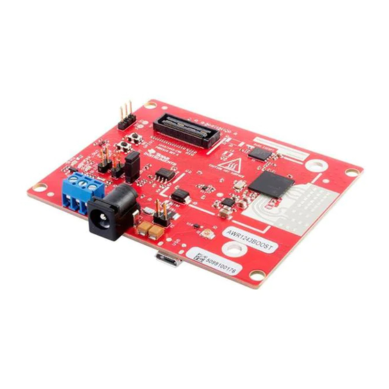
Hardware www.ti.com Heat Sink Area Micro USB Connector PMIC 20-Pin LaunchPad Connector (J5) 20-Pin LaunchPad Connector (J6) XDS110 Figure 2. EVM Rear View SWRU507 – May 2017 AWR1443BOOST, AWR1243BOOST (BoosterPack™) Submit Documentation Feedback Copyright © 2017, Texas Instruments Incorporated... -
Page 8: Block Diagram
20-pin connectors. The connectors do not have a key to prevent the misalignment of the pins or reverse connection. Therefore, ensure reverse mounting does not take place. On the AWR1443 BoosterPack, we have provided 3V3 marking near pin 1 (see Figure 4). -
Page 9: Power Connections
LaunchPads, ensure the pin 1 orientation is correct by matching the 3V3 and 5-V signal marking on the boards (see Figure Figure 6. 20-Pin BoosterPack™ Connectors (J5 and J6) SWRU507 – May 2017 AWR1443BOOST, AWR1243BOOST (BoosterPack™) Submit Documentation Feedback Copyright © 2017, Texas Instruments Incorporated... - Page 10 Enable signal is released. NOTE: To enable this feature, the R102 resister must be populated on the EVM. • ANA1/2/3/4 – These are inputs to the GPADCs (general purpose ADC) available on the AWR1443 device. AWR1443BOOST, AWR1243BOOST (BoosterPack™) SWRU507 –...
-
Page 11: High Density Connector (60 Pin)
Pin Number Description Pin Number Description SPI_CS SPI_CLK HOSTINT SPI_MOSI SPI_MISO PGOOD (onboard VIO) NERROUT SYNC_IN DEBUG_VALIDP DEBUG_VALIDM DEBUG_FRCLKP DEBUG_FRCLKM DEBUG/CSI_3P DEBUG/CSI_3M DEBUG/CSI_2P DEBUG/CSI_2M SWRU507 – May 2017 AWR1443BOOST, AWR1243BOOST (BoosterPack™) Submit Documentation Feedback Copyright © 2017, Texas Instruments Incorporated... -
Page 12: Can Connector
MCU must ensure that it does not drive any I/O signals to the AWR device before this I/O supply is stable, to avoid leakage current into the I/Os. 2.4.3 CAN Interface Connector (for AWR1443) The J3 connector provides the CAN_L and CAN_H signals (see Figure 8) from the onboard CAN transceiver (SN65HVDA540). -
Page 13: Pc Connection
Details on this board can be found at http://www.ti.com/tool/tsw1400evm For details on these use cases, see the mmWave-DevPack User Guide. SWRU507 – May 2017 AWR1443BOOST, AWR1243BOOST (BoosterPack™) Submit Documentation Feedback Copyright © 2017, Texas Instruments Incorporated... -
Page 14: Antenna
3-D plane (see Figure 10). £/2 £ RX Antennas TX Antennas Figure 10. PCB Antenna AWR1443BOOST, AWR1243BOOST (BoosterPack™) SWRU507 – May 2017 Submit Documentation Feedback Copyright © 2017, Texas Instruments Incorporated... -
Page 15: Antenna Pattern In H-Plane
(H-plane) and elevation plan (E-plane) is as shown in Figure 11 Figure Figure 11. Antenna Pattern in H-Plane Figure 12. Antenna Pattern in E-Plane SWRU507 – May 2017 AWR1443BOOST, AWR1243BOOST (BoosterPack™) Submit Documentation Feedback Copyright © 2017, Texas Instruments Incorporated... -
Page 16: Jumpers, Switches, And Leds
Jumpers, Switches, and LEDs 2.7.1 Sense On Power Jumpers The AWR1443 and AWR1243 devices can be set to operate in three different modes, based on the state of the SOP (sense on power) lines (see Figure 13). These lines are only sensed during boot up of the AWR device. -
Page 17: Push Buttons
This LED turns on if there is NERR_OUT any hardware error in the AWR device. This LED turns on when the Yellow GPIO_1 GPIO is logic-1. SWRU507 – May 2017 AWR1443BOOST, AWR1243BOOST (BoosterPack™) Submit Documentation Feedback Copyright © 2017, Texas Instruments Incorporated... -
Page 18: Design Files And Software Tools
Mechanical Mounting of PCB The field of view of the radar sensor is orthogonal to the PCB. The L-brackets provided with the AWR1443 and AWR1243 EVM kit, along with the screws and nuts help in the vertical mounting of the EVM. - Page 19 Operation of this equipment in a residential area is likely to cause harmful interference in which case the user will be required to correct the interference at his own expense. SWRU507 – May 2017 AWR1443BOOST, AWR1243BOOST (BoosterPack™) Submit Documentation Feedback Copyright © 2017, Texas Instruments Incorporated...
- Page 20 Japan with respect to EVMs. Also, do not transfer EVMs, unless User gives the same notice above to the transferee. Please note that if User does not follow the instructions above, User will be subject to penalties of Radio Law of Japan. AWR1443BOOST, AWR1243BOOST (BoosterPack™) SWRU507 – May 2017 Submit Documentation Feedback Copyright © 2017, Texas Instruments Incorporated...
- Page 21 User assumes all responsibility and liability for any improper or unsafe handling or use of the EVM by User or its employees, affiliates, contractors or designees. SWRU507 – May 2017 AWR1443BOOST, AWR1243BOOST (BoosterPack™) Submit Documentation Feedback Copyright © 2017, Texas Instruments Incorporated...
- Page 22 County, Texas. Notwithstanding the foregoing, any judgment may be enforced in any United States or foreign court, and TI may seek injunctive relief in any United States or foreign court. AWR1443BOOST, AWR1243BOOST (BoosterPack™) SWRU507 – May 2017 Submit Documentation Feedback Copyright © 2017, Texas Instruments Incorporated...
- Page 23 STANDARD TERMS FOR EVALUATION MODULES Delivery: TI delivers TI evaluation boards, kits, or modules, including any accompanying demonstration software, components, and/or documentation which may be provided together or separately (collectively, an “EVM” or “EVMs”) to the User (“User”) in accordance with the terms set forth herein.
- Page 24 FCC Interference Statement for Class B EVM devices NOTE: This equipment has been tested and found to comply with the limits for a Class B digital device, pursuant to part 15 of the FCC Rules. These limits are designed to provide reasonable protection against harmful interference in a residential installation.
- Page 25 【無線電波を送信する製品の開発キットをお使いになる際の注意事項】 開発キットの中には技術基準適合証明を受けて いないものがあります。 技術適合証明を受けていないもののご使用に際しては、電波法遵守のため、以下のいずれかの 措置を取っていただく必要がありますのでご注意ください。 1. 電波法施行規則第6条第1項第1号に基づく平成18年3月28日総務省告示第173号で定められた電波暗室等の試験設備でご使用 いただく。 2. 実験局の免許を取得後ご使用いただく。 3. 技術基準適合証明を取得後ご使用いただく。 なお、本製品は、上記の「ご使用にあたっての注意」を譲渡先、移転先に通知しない限り、譲渡、移転できないものとします。 上記を遵守頂けない場合は、電波法の罰則が適用される可能性があることをご留意ください。 日本テキサス・イ ンスツルメンツ株式会社 東京都新宿区西新宿6丁目24番1号 西新宿三井ビル 3.3.3 Notice for EVMs for Power Line Communication: Please see http://www.tij.co.jp/lsds/ti_ja/general/eStore/notice_02.page 電力線搬送波通信についての開発キットをお使いになる際の注意事項については、次のところをご覧ください。http:/ /www.tij.co.jp/lsds/ti_ja/general/eStore/notice_02.page 3.4 European Union 3.4.1 For EVMs subject to EU Directive 2014/30/EU (Electromagnetic Compatibility Directive): This is a class A product intended for use in environments other than domestic environments that are connected to a low-voltage power-supply network that supplies buildings used for domestic purposes.
- Page 26 Notwithstanding the foregoing, any judgment may be enforced in any United States or foreign court, and TI may seek injunctive relief in any United States or foreign court. Mailing Address: Texas Instruments, Post Office Box 655303, Dallas, Texas 75265 Copyright © 2017, Texas Instruments Incorporated...
- Page 27 IMPORTANT NOTICE FOR TI DESIGN INFORMATION AND RESOURCES Texas Instruments Incorporated (‘TI”) technical, application or other design advice, services or information, including, but not limited to, reference designs and materials relating to evaluation modules, (collectively, “TI Resources”) are intended to assist designers who are developing applications that incorporate TI products;...
Need help?
Do you have a question about the AWR1443 and is the answer not in the manual?
Questions and answers