Table of Contents
Advertisement
Quick Links
www.ti.com
EVM User's Guide: MCF8316DEVM
MCF8316D Evaluation Module
Description
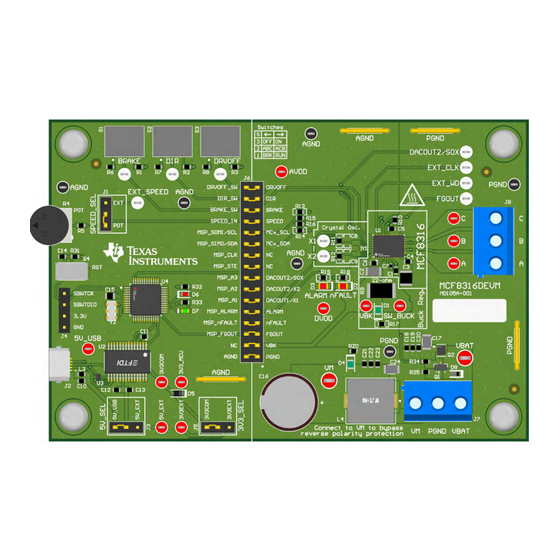
The MCF8316DEVM enables users to evaluate the
performance of the MCF8316D motor driver. The
EVM includes an onboard FTDI chip to convert USB
communication, from the micro-USB connector, into
UART. An onboard MSP430FR2355 microcontroller
(MCU) translates the UART communication into either
control signals or I2C formatted data, which is sent
to the MCF8316. There are many user-selectable
jumpers, resistors, connectors, and test points to
assist with evaluating the many features of the
MCF8316 IC and the configurable device-specific
settings.
Get Started
1. Download the latest design files from the
MCF8316DEVM tool page
2. Download the latest version of the Motor Studio
GUI and firmware from the
on ti.com
SLLU393 – OCTOBER 2024
Submit Document Feedback
on ti.com
Motor Studio tool page
Copyright © 2024 Texas Instruments Incorporated
Features
•
GUI software to simplify the MCx tuning process
and performance evaluation
•
MCU-to-MCx shunt jumper header with removable
shunts to disconnect main signals going to the
motor driver IC from the MCU
– The shunts can be removed if the user desires
to control the MCF8316 IC with an external
MCU or to use the EVM MCU to control an
external MCF8316 IC
Applications
•
Brushless-DC (BLDC) motor modules
•
Washer and Dishwasher Pumps
•
Air Purifiers and Humidifier Fans
•
Residential and Living Fans
•
CPAP Machines
Description
MCF8316D Evaluation Module
1
Advertisement
Table of Contents

Related Manuals for Texas Instruments MCF8316DEVM


Summary of Contents for Texas Instruments MCF8316DEVM
-
Page 1: Description
Description EVM User's Guide: MCF8316DEVM MCF8316D Evaluation Module Description Features The MCF8316DEVM enables users to evaluate the • GUI software to simplify the MCx tuning process performance of the MCF8316D motor driver. The and performance evaluation EVM includes an onboard FTDI chip to convert USB •... -
Page 2: Table Of Contents
8.3 Downloading Code Composer Studio and Importing GUI Firmware................16 8.4 Using eZ-FET to Program the Onboard MSP430FR2355....................9 Hardware Design Files................................. Schematics..................................18 9.2 PCB Layouts..................................9.3 Bill of Materials (BOM)..............................MCF8316D Evaluation Module SLLU393 – OCTOBER 2024 Submit Document Feedback Copyright © 2024 Texas Instruments Incorporated... - Page 3 Table of Contents 10 Additional Information................................34 11 Revision History..................................34 SLLU393 – OCTOBER 2024 MCF8316D Evaluation Module Submit Document Feedback Copyright © 2024 Texas Instruments Incorporated...
-
Page 4: Evaluation Module Overview
1 Evaluation Module Overview 1.1 Introduction This user's guide details how to set up, configure, and operate the Motor Studio GUI and MCF8316DEVM. Throughout this document, the terms evaluation board, evaluation module, and EVM are synonymous with the MCF8316DEVM. This document also provides information on the operating procedure, input and output connections, an electrical schematic, printed circuit board (PCB) layout drawings, and a bill of materials (BOM) for the EVM. -
Page 5: Specification
Evaluation Module Overview 1.4 Specification The MCF8316DEVM is rated for operation of 40V absolute maximum and currents up to 8A peak. To prevent personal injury, electrical shock hazard, damage to the EVM, or a combination confirm that the EVMs voltage and current specifications are not exceeded. -
Page 6: Hardware
Figure 2-1. Reference for Quick Start Guide 2.2 Hardware Setup The hardware required to run the motor is the MCF8316DEVM, a Micro-USB cable, and a power supply with a DC output from 4.5V to 35V. Follow these steps to start up the MCF8316DEVM: MCF8316D Evaluation Module SLLU393 –... - Page 7 5. Turn on the power supply and power up the PCB. If using the MCF8316DEVM with an external microcontroller, remove all shunt jumpers from jumper bridge J6. Connect with external jumpers to the left side of the jumper bridge from the external MCU.
-
Page 8: Hardware Connections Overview
4.5V to 35V. The MCF8316D includes three integrated half-bridges and implements a sensorless FOC algorithm to spin a motor with up to 8A peak current. It also integrates an adjustable buck regulator. For interfacing with the GUI, the MCF8316DEVM has an onboard FTDI chip and MSP430FR2355. Users Switches... -
Page 9: Connection Details
4 Connection Details Figure 4-1 shows the connections made to the MCF8316DEVM in order to spin a 3-phase sensorless Brushless- DC motor. An 4.5V to 35V power supply or battery is connected to the VBAT or VM and PGND terminals on connector J7. - Page 10 Connection Details www.ti.com Figure 4-2. Micro-USB Connector and UART for MCF8316DEVM MCF8316D Evaluation Module SLLU393 – OCTOBER 2024 Submit Document Feedback Copyright © 2024 Texas Instruments Incorporated...
-
Page 11: Msp430Fr2355 Microcontroller & User Interface
™ provide an onboard eZ-FET Debug Probe that can be jumper-wired to the MCF8316DEVM to flash the firmware into the MSP430FR2355 microcontroller. The Reset (RST) button at any time to reset and restart the MCU program. Two active-low LEDs, D6 and D7, can be used for debug purposes as well. - Page 12 MSP430FR2355 Microcontroller & User Interface www.ti.com Figure 5-1. MSP430FR2355 MCU on MCF8316DEVM MCF8316D Evaluation Module SLLU393 – OCTOBER 2024 Submit Document Feedback Copyright © 2024 Texas Instruments Incorporated...
-
Page 13: Led Lights
LED Lights 6 LED Lights The MCF8316DEVM has 6 status LEDs implemented that provide the status of power supplies and functionalities of the evaluation module. By default, the VM LED and 3.3V Buck LEDs will light up when the board is powered. -
Page 14: User-Configurable Settings
User-Configurable Settings www.ti.com 7 User-Configurable Settings The MCF8316DEVM includes a variety of user-selectable jumpers, switches, and resistors on the entirety of the evaluation board to configure settings. Table 7-1 summarizes all of these configurable settings. Table 7-1. Description of User-Selectable Settings on MCF8316DEVM... -
Page 15: Software
3. Once the Motor Studio GUI is installed, run the Motor Studio GUI application. 4. Click the Setup Now button and follow the instructions to set up the EVM. 5. After setting up the MCF8316DEVM, click on Quick Spin to begin configuring the device. Figure 8-1. Motor Studio GUI Home Page SLLU393 –... -
Page 16: Downloading Code Composer Studio And Importing Gui Firmware
1. Remove the GND, 3V3, SBWTDIO, and SBWTCK jumpers from the MSP430 LaunchPad. 2. Connect the top pins on the eZ-FET side of the LaunchPad of the GND, 3V3, SBWTCK, and SBWTDIO signals to their respective pins on J4 of the MCF8316DEVM as shown in Table 8-1 Figure 8-3. - Page 17 Software Table 8-1. Spy-Bi-Wire Connections Needed to Program the MSP430FR2355 (continued) ™ MSP430 LaunchPad (eZ-FET Debug Probe Side) (J101) MCF8316DEVM 4-pin Spi-Bi-Wire Header (J4) 3.3V SBWTDIO SBWTDIO SBWTCK SBWTCK Figure 8-3. MSP430 LaunchPad eZ-FET Debug Probe Connected to MSP430FR2355 SLLU393 –...
-
Page 18: Hardware Design Files
Y o u s hould comple te ly va lida te and te s t your de s ign imple me nta tion to confirm the s ys te m functiona lity for your a pplica tion. Engine e r: J os hua Horla nde r-Cruz Contact: http://www. ti.com/support © Te xa s Ins trume nts 2024 Figure 9-1. Interfaces MCF8316D Evaluation Module SLLU393 – OCTOBER 2024 Submit Document Feedback Copyright © 2024 Texas Instruments Incorporated... - Page 19 Y o u s hould comple te ly va lida te and te s t your de s ign imple me nta tion to confirm the s ys te m functiona lity for your a pplica tion. Engine e r: J os hua Horla nde r-Cruz Contact: http://www. ti.com/support © Te xa s Ins trume nts 2024 Figure 9-2. Driver SLLU393 – OCTOBER 2024 MCF8316D Evaluation Module Submit Document Feedback Copyright © 2024 Texas Instruments Incorporated...
- Page 20 Engine e r: J os hua Horla nde r-Cruz Contact: http://www. ti.com/support © Te xa s Ins trume nts 2024 Figure 9-3. Power and Connectors MCF8316D Evaluation Module SLLU393 – OCTOBER 2024 Submit Document Feedback Copyright © 2024 Texas Instruments Incorporated...
- Page 21 Y o u s hould comple te ly va lida te and te s t your de s ign imple me nta tion to confirm the s ys te m functiona lity for your a pplica tion. Engine e r: J os hua Horla nde r-Cruz Contact: http://www. ti.com/support © Te xa s Ins trume nts 2024 Figure 9-4. Control SLLU393 – OCTOBER 2024 MCF8316D Evaluation Module Submit Document Feedback Copyright © 2024 Texas Instruments Incorporated...
- Page 22 Y o u s hould comple te ly va lida te and te s t your de s ign imple me nta tion to confirm the s ys te m functiona lity for your a pplica tion. Engine e r: J os hua Horla nde r-Cruz Contact: http://www. ti.com/support © Te xa s Ins trume nts 2024 Figure 9-5. Hardware MCF8316D Evaluation Module SLLU393 – OCTOBER 2024 Submit Document Feedback Copyright © 2024 Texas Instruments Incorporated...
-
Page 23: Pcb Layouts
Hardware Design Files 9.2 PCB Layouts Figure 9-6. EVM Board Dimentions SLLU393 – OCTOBER 2024 MCF8316D Evaluation Module Submit Document Feedback Copyright © 2024 Texas Instruments Incorporated... - Page 24 Hardware Design Files www.ti.com Figure 9-7. EVM Top Overlay MCF8316D Evaluation Module SLLU393 – OCTOBER 2024 Submit Document Feedback Copyright © 2024 Texas Instruments Incorporated...
- Page 25 Hardware Design Files Figure 9-8. EVM Top Layer SLLU393 – OCTOBER 2024 MCF8316D Evaluation Module Submit Document Feedback Copyright © 2024 Texas Instruments Incorporated...
- Page 26 Hardware Design Files www.ti.com Figure 9-9. EVM Signal Layer 1 MCF8316D Evaluation Module SLLU393 – OCTOBER 2024 Submit Document Feedback Copyright © 2024 Texas Instruments Incorporated...
- Page 27 Hardware Design Files Figure 9-10. EVM Signal Layer 2 SLLU393 – OCTOBER 2024 MCF8316D Evaluation Module Submit Document Feedback Copyright © 2024 Texas Instruments Incorporated...
- Page 28 Hardware Design Files www.ti.com Figure 9-11. EVM Bottom Layer MCF8316D Evaluation Module SLLU393 – OCTOBER 2024 Submit Document Feedback Copyright © 2024 Texas Instruments Incorporated...
-
Page 29: Bill Of Materials (Bom)
CAP, CERM, GRM32ER71J106 10uF 10uF, 63V, +/- 1210 MuRata KA12L 10%, X7R, 1210 CAP, CERM, 0603BB104KW10 0.1uF 0.1µF, 100V,+/- Passive Plus 10%, X7R, 0603 SLLU393 – OCTOBER 2024 MCF8316D Evaluation Module Submit Document Feedback Copyright © 2024 Texas Instruments Incorporated... - Page 30 Red 0805 LED LTST-C170KRKT Lite-On Diode, Schottky, BAT165E6327HT Infineon 40V, 0.75A, AEC- SOD-323 Technologies Q101, SOD-323 Red LED, LED, Red, SMD LTST-C190KRKT Lite-On 1.6x0.8x0.8mm MCF8316D Evaluation Module SLLU393 – OCTOBER 2024 Submit Document Feedback Copyright © 2024 Texas Instruments Incorporated...
- Page 31 8A (Ta) 15W (Tc) SOT1220 BUK9D23-40EX Nexperia Surface Mount DFN2020MD-6 RES, 10.0k, R1, R2, R3, R6, 0.05%, 0.1W, 10.0k ERA-3ARW103V Panasonic R7, R8 AEC-Q200 Grade 0, 0603 SLLU393 – OCTOBER 2024 MCF8316D Evaluation Module Submit Document Feedback Copyright © 2024 Texas Instruments Incorporated...
- Page 32 SH-J15, SH-J16, SH-J17, SH-J18, SH-J19 TP1, TP2, TP3, Test Point, TP4, TP12, TP13, White Miniature Miniature, White, 5002 Keystone TP14, TP15, Testpoint TP16, TP17 MCF8316D Evaluation Module SLLU393 – OCTOBER 2024 Submit Document Feedback Copyright © 2024 Texas Instruments Incorporated...
- Page 33 MSP430FR2355T 16-Bit 24MHz LQFP48 Texas Instruments 32KB (32K x 8) FRAM 48-LQFP (7x7) Resonator, 4MHz, CSTCR4M00G55 39pF, AEC-Q200 4.5x1.2x2mm MuRata B-R0 Grade 1, SMD SLLU393 – OCTOBER 2024 MCF8316D Evaluation Module Submit Document Feedback Copyright © 2024 Texas Instruments Incorporated...
-
Page 34: Revision History
11 Revision History NOTE: Page numbers for previous revisions may differ from page numbers in the current version. DATE REVISION NOTES August 2021 Initial Release MCF8316D Evaluation Module SLLU393 – OCTOBER 2024 Submit Document Feedback Copyright © 2024 Texas Instruments Incorporated... - Page 35 TI products. TI’s provision of these resources does not expand or otherwise alter TI’s applicable warranties or warranty disclaimers for TI products. TI objects to and rejects any additional or different terms you may have proposed. IMPORTANT NOTICE Mailing Address: Texas Instruments, Post Office Box 655303, Dallas, Texas 75265 Copyright © 2024, Texas Instruments Incorporated...
Need help?
Do you have a question about the MCF8316DEVM and is the answer not in the manual?
Questions and answers