Table of Contents
Advertisement
Quick Links
Advertisement
Table of Contents

Related Manuals for MP Filtri UFM051


Summary of Contents for MP Filtri UFM051
- Page 1 User’s Manual UFM051 Mobile fi ltration unit PASSION TO PERFORM...
-
Page 3: Product Overview
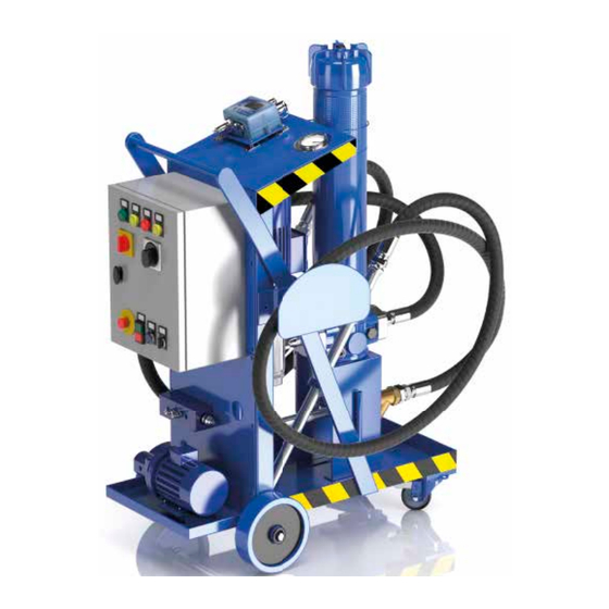
PRODUCT OVERVIEW UFM051 fi ltration unit series Key features: - Transfer - Filtration - Flow rates from 50 l/min - Maximum working pressure 10 bar - Absolute fi ltration - Wide range of fi ltration media - Water removal fi lter elements... - Page 4 Mobile filtration unit...
-
Page 5: Declaration Of Conformity
DECLARATION OF CONFORMITY EC declaration DECLARATION OF CONFORMITY IN ACCORDANCE WITH 2006/42/EC MACHINERY DIRECTIVE The company: MP Filtri S.p.A. Via 1° Maggio, 3 20042 - Pessano con Bornago (MI) - Italy as a manufacturer, it declares that the machine: Name... -
Page 6: Table Of Contents
Page PRODUCT OVERVIEW Declaration of Conformity Table of contents GENERAL WARNINGS General warnings and information for the recipient 1.1 General information 1.2 General and safety instructions 1.3 Operator station and dangerous areas 1.4 Hazards and risks that cannot be eliminated 1.5 Personal protective equipment TRANSPORT AND STORAGE Transport and handling conditions... - Page 7 TABLE OF CONTENTS Page UFM 051 - MOBILE FILTRATION UNIT Technical features Dimensions Hydraulics diagrams and material list Installation procedures and general operation Introduction Filter element installation Wiring diagram 6.3.1 Electrical connection 6.3.2 Triangular electrical connection of a three-phase motor 6.3.3 Electrical connection of a single-phase motor 6.3.4 Electrical panel 6.3.5 Electrical panel labels...
-
Page 8: General Warnings And Information For The Recipient
1 General warnings and information for the recipient 1.1 General information The mobile filtration units of the UFM series have been designed and manufactured in compliance with the machinery directive and the low voltage directive with regards to electric motors. The EC Declaration of Conformity is included in this manual. The warranty has a duration of twelve months starting from the date shown on the delivery note. - Page 9 GENERAL WARNINGS To allow rapid identification of the employees who must read this manual, definitions have been used with the following meaning: The person in charge of using the machine for productive purposes. The operator is aware of the measures taken by the machine manufacturer to eliminate the sources of risk of accidents at OPERATOR work and complies with the operational constraints.
-
Page 10: Operator Station And Dangerous Areas
1.3 Operator station and dangerous areas Areas adjacent to the electric motor due to the presence of live equipment and potentially very hot surfaces are to be considered as dangerous areas. The operator has no reason to access electrical equipment and is not authorised to do so. The trolley must be taken out of service and/or dismantled in full compliance with the regulations in force at that time in the country where the machine is installed. -
Page 11: Transport And Storage
The filtration unit is transported packaged with strapping and plastic film. The product is moved by means of wheels. The movement of the same is carried out by acting on the special handle. The weight of each individual unit is shown below: Total weight UFM051 70 Kg Mobile filtration unit... - Page 12 Mobile filtration unit...
-
Page 13: General Warranty Conditions
GENERAL WARRANTY CONDITIONS 3 Warranty, limits and exclusions 1 - The seller assumes a guarantee of the normal mechanical operation of their product for a period of one year (except as provided for in Item H4 referred to the general conditions of sale and warranty sent with each order confirmation) from the delivery date. 2 - The warranty is limited to the replacement of damaged or defective parts due to poor quality of the material or construction. -
Page 14: Mobile Transfer And Filtration Units
- off-line filtration of new oil into drums or underground/large tanks - Particle counting and determination of cleanliness class according to ISO4406, NAS1638, AS4059 (only for versions with ICM mounted on UFM051-091-181-919) - Measurement of the water saturation level (RH) contained in the fluid and of the temperature Depending on the version, the mobile filtration units can use filter elements and cartridges with different filtering media, filtration degree and dimensions;... -
Page 15: Test Certificate
PRODUCT DOCUMENTATION 4.1 Test certifi cate Hard copy of test certifi cate is attached to the cart. 4.2 Download Area Please scan the QR codes below to get updated electronic version of the related document. MOBILE FILTRATION UNIT CONTAMINATION MONITORING QUICK GUIDE PRODUCTS General catalogue... - Page 16 Mobile filtration unit...
-
Page 17: Technical Features
Ambient temperature from -20 °C to +45 °C Protection class IP 55 Seals Mineral & Synthetic oils. For other fl uids contact MP Filtri. Compatibility with hydraulic fl uids Flexible suction hose DN32 L = 3000 mm Hoses Nozzle Øe = 42... -
Page 18: Dimensions
5.1 Dimensions Filter length [mm] 1230 standard 1530 higher Drain valve Mobile filtration unit... -
Page 19: Hydraulics Diagrams And Material List
UFM051 5.2 Hydraulic circuit and bill of materials PRESSURE (OUT) G 1” Versions: UFM051MA2010P01 - UFM051TA2010P01 Position Quantity Description Y shaped filter 800 µm Gear pump / screw 50 l/min Motor/pump coupling Single-phase electric motor 1.5 kW 4P-B3/B5 (IE3) Three-phase electric motor 1.5 kW 4P-B3/B5 (IE3) Standard filter length Microfibre filter element 1 µm... - Page 20 >> NEXT Hydraulic circuit and bill of materials PRESSURE (OUT) G 1” Versions: UFM051MA3010P01 - UFM051TA3010P01 Position Quantity Description Y shaped filter 800 µm Gear pump / screw Motor/pump coupling 50 l/min Single-phase electric motor 1.5 kW 4P-B3/B5 (IE3) Three-phase electric motor 1.5 kW 4P-B3/B5 (IE3) Standard filter length Microfibre filter element 1 µm Microfibre filter element 3 µm...
- Page 21 UFM051 >> NEXT Hydraulic circuit and bill of materials PRESSURE (OUT) G 1” Version: UFM051MA3011P01 - UFM051TA3011P01 Position Quantity Description Y shaped filter 800 µm Gear pump / screw Motor/pump coupling Single-phase electric motor 1.5 kW 4P-B3/B5 (IE3) Three-phase electric motor 1.5 kW 4P-B3/B5 (IE3)
- Page 22 >> NEXT Hydraulic circuit and bill of materials PRESSURE (OUT) G 1” Versions: UFM051MA2020P01 - UFM051TA2020P01 Position Quantity Description Y shaped filter 800 µm Gear pump / screw 50 l/min Motor/pump coupling Single-phase electric motor 1.5 kW 4P-B3/B5 (IE3) Three-phase electric motor 1.5 kW 4P-B3/B5 (IE3) Increased filter length Microfibre filter element 1 µm Microfibre filter element 3 µm...
- Page 23 UFM051 >> NEXT Hydraulic circuit and bill of materials PRESSURE (OUT) G 1” Versions: UFM051MA3020P01 - UFM051TA3020P01 Position Quantity Description Y shaped filter 800 µm Gear pump / screw Motor/pump coupling 50 l/min Single-phase electric motor 1.5 kW 4P-B3/B5 (IE3) Three-phase electric motor 1.5 kW 4P-B3/B5 (IE3)
- Page 24 >> NEXT Hydraulic circuit and bill of materials PRESSURE (OUT) G 1” Version: UFM051MA3021P01 - UFM051TA3021P01 Position Quantity Description Y shaped filter 800 µm Gear pump / screw Motor/pump coupling Single-phase electric motor 1.5 kW 4P-B3/B5 (IE3) Three-phase electric motor 1.5 kW 4P-B3/B5 (IE3) Increased filter length 50 l/min Microfibre filter element 1 µm...
-
Page 25: Installation Procedures And General Operation
The standard version of the fi ltration unit is delivered without a fi lter element, before its use install an original MP Filtri fi lter element suitable for the type of unit being used (see fi lter element codes listed in Table 6.7.2 Item.7) and carry out the procedures described in Section 6.2 "Filter element... -
Page 26: Wiring Diagram
6.3 Wiring diagram 6.3.1 Electrical connection The trolley must be connected via the plug supplied to the power supply, checking: - the laws and technical specifications valid in the place and at the time of installation - that the power supply voltage and the frequency at the connection point are compatible with those indicated on the rating plate of the mobile filtration unit - the data shown on the rating plate. -
Page 27: Electrical Connection Of A Single-Phase Motor
UFM051 6.3.3 Electrical connection of a single-phase motor Depending on its type, this motor is connected to the single-phase line in only one way: - Motor with single-phase winding: Characteristic system for single-phase motors that have only a single winding, in which one end must be connected to the phase and the other end to the neutral conductor. -
Page 28: Electrical Panel Labels
Labels on the electrical panel Version with electric differential Version with electric differential indicator, red led alarm (9) on panel indicator, blue led alarm (9) on panel (for particle counter’s version only) 6.3.5 Electrical panel labels NOTE Pos. Translation of electrical panel labels ENGLISH ITALIAN FRENCH... -
Page 29: Use
UFM051 6.4 U 6.4.1 Installation The mobile filtration unit must be positioned in a place that guarantees its stability during use. TRANSFER Connect/immerse the metal suction lance (IN) to the tank or to the drum, immerse the discharge hose (OUT) in the machine tank or in the drum which should be transferred to. - Page 30 Models: Knob ON/OFF UFM051MA2010P01 UFM051TA2010P01 UFM051MA2020P01 UFM051TA2020P01 After inserting the plug, turn the rotary knob for turning on and off located on the terminal box of the electric motor to "I" (Fig. 9). At this point the transfer and filtration of the fluid begins.
-
Page 31: Air Vent
UFM051 6.4.3 Air vent When the unit is first turned on after inserting the filter element, vent the air inside the filter body using the vent valve (Fig. 14) on the cover. Once the air has been removed, close the vent valve. -
Page 32: Shutdown
6.4.5 Shutdown Models: Button ON/OFF UFM051MA2010P01 UFM051TA2010P01 UFM051MA2020P01 UFM051TA2020P01 Once the operations have been completed, switch off the electric pump, turn the shutdown switch to "0" on the terminal box of the electric motor (Fig. 17) and disconnect the electrical connection plug. With visual display Fig.17 Models:... -
Page 33: Operating Limits And Environmental Limits
6.5 Normal and scheduled maintenance The UFM051 does not require particular maintenance interventions, it is in any case a good rule to check the perfect condition of the suction and discharge hoses before each use. Check that the filter element is correctly installed and that the filter cover is tightly screwed on. -
Page 34: Filter Clogging
6.6 Filter clogging - Versions with visual differential clogging indicator UFM051MA2010P01 - UFM051TA2010P01 - UFM051MA2020P01 - UFM051TA2020P01 The conditions relating to the blockage of the filter element are guaranteed by a visual indicator (Fig. 23) mounted on the head of the LMP430 filter. - Page 35 UFM051 It is recommended to clean the fi lter cover carefully before beginning the operations for replacing the fi lter element. Fig.26 Open the vent valve Drain the oil using the oil Unscrew the cover Remove the fi lter element drain Fig.27...
-
Page 36: Air Vent
6.6.2 Air vent When the unit is first turned on after replacing the filter element, drain the air inside the filter body using the vent valve (Fig. 29) on the cover. Once the air has been removed, close the vent valve. Air vent Fig.29 Collect the oil in a container and dispose of it in accordance with the regulations in force. - Page 37 UFM051 Mobile filtration unit...
-
Page 38: Designation & Ordering Code
Particle counter option Without ICM • • With ICM 2.0 • • Option MP Filtri standard Customized CLOGGING INDICATORS (*) Visual Differential Indicator Settings Ordering code 3.0 bar ±10% DV M 30 P01 Electrical Differential Indicator (visual indication on panel) -
Page 39: Spare Parts
UFM051 8 Spare parts 22.1 22.2 8.1 List of spare parts Position Series Description Code Quantity UFM051MA2010P01 UFM051MA2020P01 UFM051MA3010P01 UFM051MA3020P01 UFM051TA2010P01 UFM051TA2020P01 Y-shaped fi lter 1-1/4” BSP - 800 µm 02200017 UFM051TA3010P01 UFM051TA3020P01 UFM051TA3011P01 UFM051TA3021P01 UFM051MA2010P01 UFM051MA2020P01 UFM051MA3010P01 UFM051MA3020P01 UFM051TA2010P01... - Page 40 >> NEXT List of spare parts Position Series Description Code Quantity UFM051MA2010P01 UFM051MA2020P01 UFM051MA3010P01 UFM051MA3020P01 UFM051TA2010P01 UFM051TA2020P01 Pump side half-coupling SGEA21FS200U UFM051TA3010P01 UFM051TA3020P01 UFM051TA3011P01 UFM051TA3021P01 UFM051MA2010P01 UFM051MA2020P01 UFM051MA3010P01 UFM051MA3020P01 UFM051TA2010P01 UFM051TA2020P01 SGEA21M04048U Motor side half-coupling UFM051TA3010P01 UFM051TA3020P01 UFM051TA3011P01 UFM051TA3021P01 UFM051MA2010P01 UFM051MA2020P01 UFM051MA3010P01 UFM051MA3020P01...
- Page 41 UFM051 >> NEXT List of spare parts Position Series Description Code Quantity Microfibre filter element 25 µm CU4005A25ANP01 Filter element in wire mesh 25 µm CU4005M25ANP01 series codes Filter element in wire mesh 60 µm CU4005M60ANP01 see previous page Water absorber filter element CU4005WA025ANP01 Microfibre filter element 1 µm...
- Page 42 >> NEXT List of spare parts Position Series Description Code Quantity UFM051MA3010P01 UFM051MA3020P01 UFM051TA2010P01 UFM051TA2020P01 Flexible suction hose DN32 L = 3000 mm 02200021 UFM051TA3010P01 Inclined cut nozzle Øe = 42 L = 700 mm UFM051TA3020P01 UFM051TA3011P01 UFM051TA3021P01 UFM051MA2010P01 UFM051MA2020P01 UFM051MA3010P01 UFM051MA3020P01 UFM051TA2010P01...
- Page 43 UFM051 >> NEXT List of spare parts Position Series Description Code Quantity UFM051TA3020P01 Fixed wheel Ø200x50x20 mm UFM051TA3011P01 02200045 Blue polyurethane coating and black polyamide structure UFM051TA3021P01 UFM051MA2010P01 UFM051MA2020P01 UFM051MA3010P01 UFM051MA3020P01 UFM051TA2010P01 Swivel wheel with Ø80x30x20 mm lock UFM051TA2020P01 Blue polyurethane coating and black polyamide structure...
-
Page 44: Filter Element Detail
All data, details and words contained in this publication are provided for use by technically qualifi ed personnel at their discretion, without warranty of any kind. MP Filtri reserves the right to make modifi cations to the models and versions of the described products at any time for both technical and/or commercial reasons. - Page 46 WORLDWIDE NETWORK CANADA RUSSIAN FEDERATION CHINA SINGAPORE FRANCE UNITED ARAB EMIRATES GERMANY UNITED KINGDOM INDIA PASSION TO PERFORM mp ltri.com...
Need help?
Do you have a question about the UFM051 and is the answer not in the manual?
Questions and answers