
Subscribe to Our Youtube Channel
Related Manuals for Leuze electronic DDLS 538 Series


Summary of Contents for Leuze electronic DDLS 538 Series
- Page 1 Original operating instructions DDLS 538 ... Optical Data Transmission for EtherCAT - Version F3/F4 We reserve the right to make technical changes EN • 2022-03-16 • 50141812...
- Page 2 © 2022 Leuze electronic GmbH + Co. KG In der Braike 1 73277 Owen / Germany Phone: +49 7021 573-0 Fax: +49 7021 573-199 www.leuze.com info@leuze.com Leuze electronic GmbH + Co. KG DDLS 538 ...
-
Page 3: Table Of Contents
Setting the operating mode.................... 43 Fine adjustment ........................ 46 6.2.1 General procedure ...................... 46 6.2.2 Fine adjustment with the single-handed adjustment (SHA) process......... 47 6.2.3 Fine adjustment without the single-handed adjustment (SHA) process...... 48 Leuze electronic GmbH + Co. KG DDLS 538 ... - Page 4 11.2 Dimensioned drawings ...................... 71 11.3 Dimensional drawings: Accessories .................. 73 Order guide and accessories................ 74 12.1 Nomenclature ........................ 74 12.2 Cables accessories....................... 74 12.3 Other accessories ......................... 75 EC Declaration of Conformity................ 76 Leuze electronic GmbH + Co. KG DDLS 538 ...
-
Page 5: About This Document
Text passages with this symbol provide you with further information. Symbol for action steps Text passages with this symbol instruct you to perform actions. Symbol for action results Text passages with this symbol describe the result of the preceding action. Leuze electronic GmbH + Co. KG DDLS 538 ... -
Page 6: Safety
Ä The device must not be opened. There are no user-serviceable parts inside. Ä Repairs must only be performed by Leuze electronic GmbH + Co. KG. Leuze electronic GmbH + Co. KG DDLS 538 ... -
Page 7: Competent Persons
• The device is not being used properly. • Reasonably foreseeable misuse is not taken into account. • Mounting and electrical connection are not properly performed. • Changes (e.g., constructional) are made to the device. Leuze electronic GmbH + Co. KG DDLS 538 ... -
Page 8: Laser Safety Notices
Ä The device must not be tampered with and must not be changed in any way. There are no user-serviceable parts inside the device. Repairs must only be performed by Leuze electronic GmbH + Co. KG. The device emits invisible laser radiation with a wavelength of 785 nm (device with designation "Frequency F3") or 852 nm (device with designation "Frequency F4") through the laser aperture of the... - Page 9 Pulse duration: 32 ns 32 ns Wavelength: 785 nm 785 nm CLASS 1M LASER PRODUCT IEC 60825-1:2014 IEC 60825-1:2014 Complies with 21 CFR 1040.10 Fig. 2.2: Laser information signs for devices with frequency F3 Leuze electronic GmbH + Co. KG DDLS 538 ...
- Page 10 NOTICE Devices with integrated alignment laser can be identified by part number code L in the part des- ignation, e.g., DDLS 5xx XXX.4 L. Laser class 1M also applies for devices with integrated alignment laser. Leuze electronic GmbH + Co. KG DDLS 538 ...
-
Page 11: Device Description
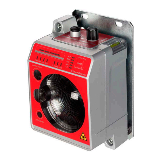
Supporting edge for bubble level or alignment straight- edge LED indicators in the control panel EtherCAT connection, M12 Spirit level (for devices with alignment laser) POWER connection, M12 Fig. 3.1: Device construction Leuze electronic GmbH + Co. KG DDLS 538 ... -
Page 12: Performance Characteristics And Delivery Options
3.1.4 Accessories For exact details and order information, see chapter 12 "Order guide and accessories". • Adapter plate for installing instead of a DDLS 200 • Ready-made cable for M12 connections Leuze electronic GmbH + Co. KG DDLS 538 ... - Page 13 Device description • Customizable connector plug Leuze electronic GmbH + Co. KG DDLS 538 ...
-
Page 14: Operating Principle
The intensity warning is applied on switching output IO1 of the POWER connection. Connection technology A-coded, M12 connection for the supply voltage with integrated switching input and output. D-coded, M12 connection for the EtherCAT connection. Leuze electronic GmbH + Co. KG DDLS 538 ... -
Page 15: Indicators And Operational Controls
LAS – Alignment laser for mounting support LLC – Link Loss Counter MAS – DDLS 538 … installed on the master side MODE – Operating mode selector switch Fig. 3.3: Operating mode LEDs, configuration LED, and operating mode selector switch Leuze electronic GmbH + Co. KG DDLS 538 ... - Page 16 Note: For master-side installation, the MAS configuration must be activated on the device. For slave-side installation, the MAS configuration must be deactivated on the device. DDLS 538 … slave side installed. Green Continuous light DDLS 538 … master side installed. Leuze electronic GmbH + Co. KG DDLS 538 ...
- Page 17 Device error (see chapter 8.1 "Error displays of the operating state LEDs" • The function of the device is limited. The displays of the other operating state LEDs may pro- vide information on the cause of the error. Leuze electronic GmbH + Co. KG DDLS 538 ...
- Page 18 • Transmitter of the second device deactivated Green Continuous light • The optical link exists. • No data is sent or received. Orange Continuous light/ Data is sent and received. flickering light Leuze electronic GmbH + Co. KG DDLS 538 ...
- Page 19 If the received signal level drops, the LEDs are successively switched off, beginning with the green LEDs. two red LEDs two orange LEDs four green LEDs Fig. 3.5: SIGNAL QUALITY indicator of the received signal level Leuze electronic GmbH + Co. KG DDLS 538 ...
- Page 20 • Wrong F3/F4 frequency assignment of the devices • Transmitter of the second device deactivated MAS EtherCAT configuration is activated on both devices. MAS EtherCAT configuration is deactivated on both de- vices. Leuze electronic GmbH + Co. KG DDLS 538 ...
-
Page 21: Indicators In The Optics Area
• The transmitter is deactivated (see chapter 8.2 "Error dis- plays and STATUS LED for remote diagnosis"). • MAS EtherCAT configuration is activated on both devices or MAS EtherCAT configuration is deactivated on both de- vices. Leuze electronic GmbH + Co. KG DDLS 538 ... -
Page 22: Indicators In The Connection Area
• The link to the connected device is OK. light • No data is sent or received. Orange Continuous • The link to the connected device is active. light/ • Data is sent and received. flickering light Leuze electronic GmbH + Co. KG DDLS 538 ... -
Page 23: Mounting
C profile rails. NOTICE If the device is mounted instead of a DDLS 200, use the adapter plate – to be ordered sepa- rately – if necessary (see chapter 12.3 "Other accessories"). Leuze electronic GmbH + Co. KG DDLS 538 ... -
Page 24: Mounting With Alignment Laser And Level
• The laser spot of the alignment laser shows the installation position of the mutually opposing device. 4.2.1 Horizontal mounting (travel axis) with the alignment laser A drilling template is included with the packaging. all dimensions in mm Fig. 4.1: Drilling template Leuze electronic GmbH + Co. KG DDLS 538 ... - Page 25 Ä Switch on the alignment laser. Activate the LAS (Alignment laser) operating mode to switch on the alignment laser (see chapter 6.1 "Setting the operating mode"). NOTICE Data transmission is active while changing the operating mode and with activated alignment laser. Leuze electronic GmbH + Co. KG DDLS 538 ...
- Page 26 44 m 2.5 m 5.6 m 7.7 m 11.8 m 23.8 m 40 m 2.0 m 4.5 m 6.2 m 9.4 m 19.0 m 37 m 1.5 m 3.4 m 4.6 m 7.1 m 14.3 m 32 m 1.0 m 2.2 m 3.1 m 4.7 m 9.5 m 25 m 0.5 m 1.1 m 1.5 m 2.4 m 4.8 m 16 m Leuze electronic GmbH + Co. KG DDLS 538 ...
- Page 27 (7) that is parallel to the guide rail. ð If possible, use laser spot 1 and laser spot 3 for alignment. ð Set the distances of the laser spots to the reference edge exactly to 1 mm. Leuze electronic GmbH + Co. KG DDLS 538 ...
- Page 28 Ä Detach the contour of the optical window from the drilling template along the perforation. Affix the re- moved drilling template to the optical window of the device that was mounted first using the supplied self-adhesive labels. Leuze electronic GmbH + Co. KG DDLS 538 ...
- Page 29 ð After the start-up phase, the operating mode can be changed. Ä Switch on the alignment laser of the second device. Activate the LAS (Alignment laser) operating mode to switch on the alignment laser (see chapter 6.1 "Setting the operating mode"). Leuze electronic GmbH + Co. KG DDLS 538 ...
-
Page 30: Vertical Mounting (Lifting Axis) With The Alignment Laser
Ä Mount the two devices opposite one another with a lateral offset of 30 mm. Mount the devices so that the center of the transmitter of one device is opposite the center of the receiver of the other device. 30 mm Fig. 4.7: Lateral offset of the devices with vertical mounting Leuze electronic GmbH + Co. KG DDLS 538 ... -
Page 31: Mounting Without Alignment Laser
Ä Observe the mounting instructions (see chapter 4.1 "Mounting instructions"). NOTICE You will achieve greater flexibility during basic installation and fine adjustment if you mount the devices on C profile rails. Leuze electronic GmbH + Co. KG DDLS 538 ... -
Page 32: Horizontal Mounting (Travel Axis) Without Alignment Laser
ð Mounting of the device is concluded. Further procedure: • Connect the devices electrically (see chapter 5 "Electrical connection"). • Perform the fine adjustment for the travel axis (see chapter 6.2 "Fine adjustment"). Leuze electronic GmbH + Co. KG DDLS 538 ... -
Page 33: Vertical Mounting (Lifting Axis) Without Alignment Laser
ð Mounting of the device is concluded. Further procedure: • Connect the devices electrically (see chapter 5 "Electrical connection"). • Perform the fine adjustment for the lifting axis (see chapter 6.2 "Fine adjustment"). Leuze electronic GmbH + Co. KG DDLS 538 ... -
Page 34: Mounting Tolerances Of The Devices
Rotary transmission possible with device separation (3) of greater than 500 mm Fig. 4.10: Maximum allowed mounting tolerance The maximum mounting tolerance is calculated using the following formula: [mm] Maximum mounting tolerance of the devices [mm] Applied minimum distance in the system Leuze electronic GmbH + Co. KG DDLS 538 ... -
Page 35: Mounting Distance For Parallel Operation Of Data Transmission Systems
The minimum mounting distance between two optical data transmission systems is determined by the fol- lowing criteria: • Maximum data transmission distance • Frequency-offset mounting (F3/F4 / F4/F3) • Identical frequency mounting (F3/F4 / F3/F4) • Transmission beam spread of the devices The standard beam spread is ±0.5°. Leuze electronic GmbH + Co. KG DDLS 538 ... - Page 36 Minimum mounting distance between the devices 40 m (DDLS 538 40.xxx) 300 mm 120 m (DDLS 538 120.xxx) 300 mm 200 m (DDLS 538 200.xxx) 500 mm Identical-frequency mounting Minimum mounting distance Device with frequency 3 (Frequency F3, DDLS 5XX xxx. 3-YY) Device with frequency 4 (Frequency F4, DDLS 5XX xxx. 4-YY) Fig. 4.13: Identical-frequency mounting Leuze electronic GmbH + Co. KG DDLS 538 ...
-
Page 37: Mounting Distance For Parallel Operation With Ams 300/Ams 200 Laser Measurement Systems
If there are multiple optical data transmission paths between two participants (TN), one speaks of cascad- ing. Optical data transmission path 1 Optical data transmission path 2 Fig. 4.14: Example: Cascading of multiple data transmission systems Leuze electronic GmbH + Co. KG DDLS 538 ... - Page 38 D D LS 538 D D LS 538 S lave S lave F requency F requency F requency F requency Master Bus terminals Fig. 4.15: Cascading with slave participant between the data transmission paths Leuze electronic GmbH + Co. KG DDLS 538 ...
- Page 39 Cascading without slave participant between the data transmission paths Delay times The following delay times apply for the DDLS 538 …: • Constant delay time per path (2 devices): 5 µs • Distance-dependent delay: Distance 0 m: 0 µs Distance 200 m: 0.66 µs Leuze electronic GmbH + Co. KG DDLS 538 ...
-
Page 40: Electrical Connection
Ä Lay all connection cables and signal lines within the electrical installation space or perma- nently in cable ducts. Ä Lay the cables and lines so that they are protected against external damages. Ä For further information: see EN ISO 13849-2, Table D.4. Leuze electronic GmbH + Co. KG DDLS 538 ... -
Page 41: Power (Supply Voltage / Switching Input And Switching Output)
Data transmission remains active until the last orange LED of the SIGNAL QUALITY indicator switches off. Data transmission is then deactivated. The intensity warning remains active even after the last orange LED of the SIGNAL QUALITY indicator switches off. Leuze electronic GmbH + Co. KG DDLS 538 ... -
Page 42: Bus (Bus Input, Ethercat)
The shielding connection must be at the same potential at both ends of the data line. This serves to prevent potential equalization currents over the shield and possible interference cou- pling through compensating currents. Ä Use at least a CAT 5 cable for the connection. Leuze electronic GmbH + Co. KG DDLS 538 ... -
Page 43: Starting Up The Device
(SHA) process"). Manual Data transmission switches off as soon as no green LEDs in the SIGNAL QUALITY indicator illuminate. Note: The AUT LED switches off if the MAN operating mode is activated. Leuze electronic GmbH + Co. KG DDLS 538 ... - Page 44 Note: The device on which the MAS EtherCAT configuration is activated only estab- lishes a cable-connected Ethernet link if the optical link exists between the two de- vices and the slave-side device has already established a cable-connected link. Leuze electronic GmbH + Co. KG DDLS 538 ...
- Page 45 ð Press the operating mode selector switch [MODE] for approx. two seconds until the MAS LED illu- minates continuously. ð Release the operating mode selector switch [MODE] to activate the MAS EtherCAT configuration. ð The MAS LED illuminates continuously. Leuze electronic GmbH + Co. KG DDLS 538 ...
-
Page 46: Fine Adjustment
• One person monitors the "Signal Quality". • The second person adjusts the transmitter at the mutually opposing device. Decide which of the two processes to use; explanations can be found in the following chapters. Leuze electronic GmbH + Co. KG DDLS 538 ... -
Page 47: Fine Adjustment With The Single-Handed Adjustment (Sha) Process
ð The devices are now ready. NOTICE At the maximum transmission distance, the SIGNAL QUALITY indicator may be one or two green LEDs short of end-scale deflection. Data transmission is, however, still active. Leuze electronic GmbH + Co. KG DDLS 538 ... -
Page 48: Fine Adjustment Without The Single-Handed Adjustment (Sha) Process
(see chapter 3.1.1 "device construction"). To do this, communication with the second person is required at the mutually opposing device. ð Note: The second person on the mutually opposing device notifies you of their "Signal Quality" indicator. Leuze electronic GmbH + Co. KG DDLS 538 ... - Page 49 ð The devices are now ready. NOTICE At the maximum transmission distance, the SIGNAL QUALITY indicator may be one or two green LEDs short of end-scale deflection. Data transmission is, however, still active. Leuze electronic GmbH + Co. KG DDLS 538 ...
-
Page 50: Ethercat
I/O ‘s I/O ‘s D D LS 538 D D LS 538 D D LS 538 D D LS 538 I/O ‘s I/O ‘s Master Bus terminals Stationary Mobile Chassis Lifting unit Leuze electronic GmbH + Co. KG DDLS 538 ... -
Page 51: Mas Ethercat Configuration Of The Ddls 538
I/O ‘s „M A S “ = off „M A S “ = on Master Bus terminals DDLS 538 … master side DDLS 538 … slave side Operating mode/MAS configuration = on Fig. 7.1: MAS EtherCAT configuration activated Leuze electronic GmbH + Co. KG DDLS 538 ... -
Page 52: Ethercat Factory Setting
Factory setting of the MAS EtherCAT configuration The DDLS 538 … are delivered ex works with the following MAS EtherCAT configuration: • Device with "Frequency F4": MAS EtherCAT configuration activated • Device with "Frequency F3": MAS EtherCAT configuration deactivated Leuze electronic GmbH + Co. KG DDLS 538 ... -
Page 53: Operation With Ethercat Factory Setting
Ä In the case of moving machine or system parts, an emergency stop can result in property damage and personal injury. Ä Leuze electronic GmbH + Co. KG accepts no liability if the installation and mounting regula- tions are not observed. Leuze electronic GmbH + Co. KG DDLS 538 ... -
Page 54: Alternative Mas Ethercat Configuration
„M A S “ = off „M A S “ = on Master Bus terminals Master-side installation Slave-side installation Device with "Frequency F3" Fig. 7.5: Alternative MAS EtherCAT configuration: device with "Frequency F3" installed on master side Leuze electronic GmbH + Co. KG DDLS 538 ... -
Page 55: Control Requirement
• Due to interruptions of the optical link between the two opposing DDLS 538 devices, • e.g., due to persons who interrupt the optical link during commissioning or maintenance work • exceeding the open angle of the DDLS 538 due to external vibrations/oscillations Leuze electronic GmbH + Co. KG DDLS 538 ... -
Page 56: Difference Between Ddls 538
Ä The actual control cycle time must be greater than or equal to the calculated minimum cycle time. Ä The DDLS 538 … S2 and DDLS 538 … S3 should not be used for control cycle times that are shorter than the calculated minimum control cycle time. Leuze electronic GmbH + Co. KG DDLS 538 ... -
Page 57: Control Cycle Times When Cascading Data Transmission Paths
In doing so, the EtherCAT master runs through the Init > Pre-Operational > Safe-Operational > Operational operating states. In the Operational operating state of the EtherCAT master, the EtherCAT participants are again addressable. Leuze electronic GmbH + Co. KG DDLS 538 ... - Page 58 D D LS 538 D D LS 538 S lave S lave F requency F requency F requency F requency Master Bus terminals Fig. 7.6: Cascading with slave participant between the data transmission paths Leuze electronic GmbH + Co. KG DDLS 538 ...
-
Page 59: Distributed Clocks
• At a maximum expected speed of the stacker crane of 10 m/s, this will traverse a distance of 100 m within 10 s*. (*: the propagation time delay is remeasured every 10 s) Leuze electronic GmbH + Co. KG DDLS 538 ... - Page 60 When cascading data transmission paths without DC-capable slave between the data transmis- sion devices, the propagation time difference may increase further, but remains below the per- missible deviation of 2 µs. The DDLS 538 … is, thus, suitable for DC-synchronized applications. Leuze electronic GmbH + Co. KG DDLS 538 ...
-
Page 61: Diagnostics And Troubleshooting
Data transmission remains active if above or below the operating temperature. An operating hour counter is started internally that records the operating time outside of the specified operating temperature. In this case, the laser diode is excluded from guarantee services. Leuze electronic GmbH + Co. KG DDLS 538 ... - Page 62 • Check F3/F4 frequency assignment of • Wrong frequency assign- the devices. ment of the devices • End deactivation of the transmitters. • Transmitter deactivated • Transmitter of the second device deactivated Leuze electronic GmbH + Co. KG DDLS 538 ...
- Page 63 Check LSR LED. Tab. 8.6: LINK and LINK/ACT LED displays – Causes and measures Color State possible causes Measures LINK No cable-connected link to the con- Check EtherCAT cable nected device. connection. LINK/ Leuze electronic GmbH + Co. KG DDLS 538 ...
-
Page 64: Error Displays And Status Led For Remote Diagnosis
• Eliminate the possibility of environmental influences such as snow, rain, fog • Laser diode: at end of life expectancy Check LSR LED (see chapter 8.1 "Error displays of the operating state LEDs"). Leuze electronic GmbH + Co. KG DDLS 538 ... -
Page 65: Error Displays Of The Operating Mode Leds
(see chapter 7.2 "MAS EtherCAT configuration of the DDLS 538 …"): MAS EtherCAT configuration is deactivated on both devices. • Device installed on master side: activate MAS • Device installed on slave side: deactivate MAS Leuze electronic GmbH + Co. KG DDLS 538 ... -
Page 66: Care, Maintenance And Disposal
Repairs to the device must only be performed by the manufacturer. Ä For repairs, contact your responsible Leuze subsidiary or Leuze customer service (Service and sup- port). Disposing Ä For disposal observe the applicable national regulations regarding electronic components. Leuze electronic GmbH + Co. KG DDLS 538 ... -
Page 67: Service And Support
Contact & Support > Repair Service & Returns. To ensure quick and easy processing of your request, we will send you a returns order with the returns ad- dress in digital form. Leuze electronic GmbH + Co. KG DDLS 538 ... -
Page 68: Technical Data
Approx. 200 mA at 24 V DC (no load at switching output) Data transmission delay time Constant delay time per path (2 devices): 5 µs Distance-dependent delay: • Distance 0 m: 0.00 µs • Distance 200 m: 0.66 µs Leuze electronic GmbH + Co. KG DDLS 538 ... - Page 69 Conformity CE, CDRH Certifications UL 60950-1, CSA C 22.2 No. 60950-1 CAUTION UL applications! For UL applications, use is only permitted in Class 2 circuits in accordance with the NEC (Na- tional Electric Code). Leuze electronic GmbH + Co. KG DDLS 538 ...
-
Page 70: 11.1.2 Device With Heating
Minimum 30 min at +24 V DC and an ambient temperature of -35 °C Minimum conductor cross section Conductor cross section of at least 0.75 mm² for the supply voltage supply line Tab. 11.8: Environmental data Ambient temperature (operation) -35 °C … +50 °C Leuze electronic GmbH + Co. KG DDLS 538 ... -
Page 71: Dimensioned Drawings
Technical data 11.2 Dimensioned drawings all dimensions in mm Center axis of transmitter and alignment laser Center axis of transmitter and receiver Center axis of receiver Fig. 11.1: Dimensioned drawing of DDLS 538 40.xxx, DDLS 538 120.xxx Leuze electronic GmbH + Co. KG DDLS 538 ... - Page 72 Dimensioned drawing of DDLS 538 200.xxx NOTICE Installation for devices with an operating range of 200 m. Ä Always install the Frequency F4 device as stationary device for devices with an operating range of 200 m (DDLS 538 200…). Leuze electronic GmbH + Co. KG DDLS 538 ...
-
Page 73: Dimensional Drawings: Accessories
Technical data 11.3 Dimensional drawings: Accessories all dimensions in mm Fig. 11.3: Dimensioned drawing of adapter plate for DDLS 200 replacement Leuze electronic GmbH + Co. KG DDLS 538 ... -
Page 74: Order Guide And Accessories
Connection cable, M12 socket, axial plug outlet, open cable end, cable length 5 m, not shielded 50132080 KD U-M12-5A-V1-100 Connection cable, M12 socket, axial plug outlet, open cable end, cable length 10 m, not shielded Leuze electronic GmbH + Co. KG DDLS 538 ... -
Page 75: Other Accessories
M12 socket, axial, A-coded for supply voltage, shielded 50108991 D-ET1 RJ45 plug, user-configurable / screw connections 50112155 S-M12A-ET M12 plug, axial, D-coded, user-configurable / screw connections 50109832 KDS ET M12 / RJ45 W-4P Converter from M12, D-coded, to RJ-45 socket Leuze electronic GmbH + Co. KG DDLS 538 ... -
Page 76: Ec Declaration Of Conformity
The optical data transmission systems of the DDLS 500 series were developed and manufactured in accor- dance with the applicable European standards and directives. The manufacturer of the product, Leuze electronic GmbH + Co KG in D-73277 Owen, possesses a certified quality assurance system in accordance with ISO 9001. Leuze electronic GmbH + Co. KG DDLS 538 ...
Need help?
Do you have a question about the DDLS 538 Series and is the answer not in the manual?
Questions and answers