Table of Contents
Advertisement
Quick Links
User Manual
GO-5100M-PGE-1 GO-5100C-PGE-1
GO-5101M-PGE-1 GO-5101C-PGE-1
Thank you for purchasing this product.
Be sure to read this documentation before use.
This documentation includes important safety precautions and instructions on how to operate the unit. Be sure to read this documentation to ensure
proper operation.
The contents of this documentation are subject to change without notice for the purpose of improvement.
© 2023 JAI
CMOS Digital Progressive Scan
Monochrome and Color Camera with GigE Interface
Document Version: 1.0
Date: 2023/09/15
Advertisement
Table of Contents

Related Manuals for JAI GO-5100M-PGE-1


Summary of Contents for JAI GO-5100M-PGE-1
- Page 1 User Manual GO-5100M-PGE-1 GO-5100C-PGE-1 GO-5101M-PGE-1 GO-5101C-PGE-1 CMOS Digital Progressive Scan Monochrome and Color Camera with GigE Interface Document Version: 1.0 Date: 2023/09/15 Thank you for purchasing this product. Be sure to read this documentation before use. This documentation includes important safety precautions and instructions on how to operate the unit. Be sure to read this documentation to ensure proper operation.
-
Page 2: Table Of Contents
GO-5100MC-PGE-1 | GO-5101MC-PGE-1 | User Manual (Ver. 1.0) Table of Contents Table of Contents Table of Contents About Technical Note Notice/Warranty Notice Warranty Certifications CE Compliance Warning China RoHS Usage Precautions Notes on Cable Configurations Notes on LAN Cable Connection Notes on Attaching the Lens Phenomena Specific to CMOS Image Sensors Notes on Exportation... - Page 3 GO-5100MC-PGE-1 | GO-5101MC-PGE-1 | User Manual (Ver. 1.0) Table of Contents Preparation Step 1: Install the Software (First Time Only) Step 2: Connect Devices ① Lens ② Direct Mounting (or Use MP-43 Tripod Adapter Plate) ③ LAN Cable ➃ Network Card ⑤...
- Page 4 GO-5100MC-PGE-1 | GO-5101MC-PGE-1 | User Manual (Ver. 1.0) Table of Contents Shortest Repetition Period for Triggers Event Control Gain Control LUT (Lookup Table) Gamma Function Line Status Defective Pixel Correction Function Automatic Detection Manual configuration ShadingCorrection To Use the Shading Correction Function Binning Function ROI (Region of Interest) Settings Sensor Multi ROI Function...
- Page 5 GO-5100MC-PGE-1 | GO-5101MC-PGE-1 | User Manual (Ver. 1.0) Table of Contents EventControl AnalogControl LUTControl SequencerControl Digital IO Control PulseGenerators TransportLayerControl ActionControl UserSetControl ChunkDataControl JAICustomControlALC JAICustomControlBlemish JAICustomControlShading JAICustomControlMultiROI JAICustomCounterAndTimerControl JAICustomControlAWB JAICustomControlMisc Miscellaneous Troubleshooting Power Supply and Connections Image Display Settings and Operations Specifications Package contents Optional accessories (not supplied)
-
Page 6: About Technical Note
Table of Contents About Technical Note Some additional technical information is provided on the JAI website as Technical Notes. In this manual, if a technical note is available for a particular topic, the above icon is shown. Please refer to the following URL for Technical notes. -
Page 7: Notice/Warranty
The material contained in this manual consists of information that is proprietary to JAI Ltd., Japan, and may only be used by the purchasers of the product. JAI Ltd., Japan makes no warranty for the use of its product and assumes no responsibility for any errors which may appear or for damages resulting from the use of the information contained herein. -
Page 8: Warning
GO-5100MC-PGE-1 | GO-5101MC-PGE-1 | User Manual (Ver. 1.0) Notice/Warranty Connect the equipment into an outlet on a circuit different from that to which the receiver is connected. Consult the dealer or an experienced radio/TV technician for help. Warning Changes or modifications to this unit not expressly approved by the party responsible for FCC compliance could void the user’s authority to operate the equipment. -
Page 9: China Rohs
根据中华人民共和国信息产业部『电器电子产品有害物质限制使用管理办法』, 本产品《有毒有害 物质或元素名称及含量表》如下. 有毒有害物质或元素 部件名称 六价铬 多溴联苯 多溴二苯醚 铅 汞 镉 (Cr (VI)) (PBB) (PBDE) (Pb) (Hg) (Cd) GO-5100M-PGE-1 GO-5100C-PGE-1 × 〇 〇 〇 〇 〇 GO-5101M-PGE-1 GO-5101C-PGE-1 〇:表示该有毒有害物质在该部件所有均质材料中的含量均在 GB/T 26572-2011规定的限量要求以下。 ×:表示该有毒有害物质至少在该部件的某一均质材料中的含量超出 GB/T 26572-2011规定的限量要求。 环保使用期限 电子信息产品中含有的有毒有害物质或元素在正常使用的条件下不会发生外 泄或突变、 电子信息产品用户使用该电子信息产品不会对环境造成严重污染 或对其人身、财产造成 严重损害的期限。... -
Page 10: Usage Precautions
GO-5100MC-PGE-1 | GO-5101MC-PGE-1 | User Manual (Ver. 1.0) Usage Precautions Usage Precautions Notes on Cable Configurations The presence of lighting equipment and television receivers nearby may result in video noise. In such cases, change the cable configurations or placement. Notes on LAN Cable Connection Secure the locking screws on the connector manually, and do not use a driver. -
Page 11: Phenomena Specific To Cmos Image Sensors
GO-5100MC-PGE-1 | GO-5101MC-PGE-1 | User Manual (Ver. 1.0) Usage Precautions Phenomena Specific to CMOS Image Sensors The following phenomena are known to occur on cameras equipped with CMOS image sensors. These do not indicate malfunctions. Aliasing: When shooting straight lines, stripes, and similar patterns, vertical aliasing (zigzag distortion) may appear on the monitor. -
Page 12: Features
GO-5100MC-PGE-1 | GO-5101MC-PGE-1 | User Manual (Ver. 1.0) Features Features This camera is an industrial progressive scan camera equipped with a 2/3-inch global shutter CMOS image sensor with 5.1 effective megapixels (2464 × 2056). The unit is compact and lightweight in design and is equipped with GigE Vision Ver. - Page 13 GO-5100MC-PGE-1 | GO-5101MC-PGE-1 | User Manual (Ver. 1.0) Features Variety of Pre-Process Functions LUT (lookup table): For programmable control over gamma and contrast. Gamma correction: Gamma can be set to 0.45, 0.60, or 1.0 (off). Shading correction (flat field and color shading): Non-uniformity (i.e., shading) in the amount of light generated by the lens and lighting equipment can be corrected.
-
Page 14: Parts Identification
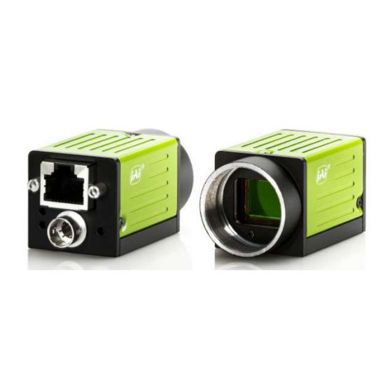
GO-5100MC-PGE-1 | GO-5101MC-PGE-1 | User Manual (Ver. 1.0) Parts Identification Parts Identification ① Lens Mount (C-Mount) ② RJ-45 Connector ③ POWER/TRIG LED ④ LINK LED ⑤ ACT LED ⑥ DC IN/TRIG Connector (6-Pin Round) ⑦ Mounting Holes (M3, 3mm depth) ① Lens Mount (C-Mount) Mount a C-mount lens, microscope adapter, etc. -
Page 15: ② Rj-45 Connector
GO-5100MC-PGE-1 | GO-5101MC-PGE-1 | User Manual (Ver. 1.0) Parts Identification ② RJ-45 Connector Connect a Gigabit Ethernet compatible LAN cable (Category 5e or higher, Category 6 recommended) here. GigE Vision Interface Pin No. Input/Output Signal In/Out MX1+ (DA+) In/Out MX1– (DA–) In/Out MX2+ (DB+) In/Out... -
Page 16: ④ Link Led
GO-5100MC-PGE-1 | GO-5101MC-PGE-1 | User Manual (Ver. 1.0) Parts Identification ④ LINK LED Indicates whether the GigE network connection is established or not. Status The network link is not established (or in progress). Lit green 1000Base-T link is established. ⑤ ACT LED Indicates the GigE network status. -
Page 17: ⑥ Dc In/Trig Connector (6-Pin Round)
GO-5100MC-PGE-1 | GO-5101MC-PGE-1 | User Manual (Ver. 1.0) Parts Identification ⑥ DC IN/TRIG Connector (6-Pin Round) Connect the cable for a power supply (optional) or for DC IN / trigger IN here. Camera Side: HR10A-7R-6PB (73) (Hirose Electric or equivalent) Cable Side: HR10A-7P-6S (Plug) (Hirose Electric or equivalent) Pin No. -
Page 18: Recommended Circuit Diagram (Reference Examples)
GO-5100MC-PGE-1 | GO-5101MC-PGE-1 | User Manual (Ver. 1.0) Parts Identification Recommended Circuit Diagram (Reference Examples) Related Setting Items: Digital IO Control OPTO-In Circuit Characteristics Recommended External Input Circuit Diagram Recommended External Output Circuit Diagram (Reference Example) - 18 -... -
Page 19: Characteristics Of The Recommended Circuits For Opto Out
GO-5100MC-PGE-1 | GO-5101MC-PGE-1 | User Manual (Ver. 1.0) Parts Identification Characteristics of the Recommended Circuits for Opto OUT OUTPUT LINE RESPONSE TIME - 19 -... -
Page 20: Preparation
Read this section to learn how the camera connects to devices and accessories. The preparation process is described below. Step 1: Install the Software (First Time Only) Install the software for configuring and controlling the camera (eBUS SDK for JAI) on the computer. Step 2: Connect Devices Connect the lens, LAN cable, AC adapter, computer, and other devices. -
Page 21: Step 1: Install The Software (First Time Only)
When using the camera for the first time, install the software for configuring and controlling the camera (eBUS SDK for JAI) on the computer. Note: When you install eBUS SDK for JAI, eBUS Player for JAI will also be installed. 1. Download the eBUS SDK for JAI from the JAI website (https://www.jai.com/support-software/jai-... -
Page 22: ① Lens
GO-5100MC-PGE-1 | GO-5101MC-PGE-1 | User Manual (Ver. 1.0) Preparation ① Lens C-mount lenses with lens mount protrusions of 9 mm or less can be attached. The diagonal of the camera’s CMOS image sensor is 11 mm, the size of standard 2/3-inch lenses. To prevent vignetting and to obtain the optimal resolution, use a lens that will cover the 11 mm diagonal. -
Page 23: ③ Lan Cable
GO-5100MC-PGE-1 | GO-5101MC-PGE-1 | User Manual (Ver. 1.0) Preparation ③ LAN Cable Connect a LAN cable to the RJ-45 connector. Use a LAN cable that is Category 5e or higher (Category 6 recommended). When supplying power via PoE, connect to a PoE-compatible switching hub or a PoE- compatible network card. -
Page 24: Step 3: Verify Camera Operation
Step 4: Verify the Connection between the Camera and PC Verify whether the camera is properly recognized via Control Tool. 1. Launch eBUS Player for JAI eBUS Player for JAI startup screen appears. - 24 -... - Page 25 GO-5100MC-PGE-1 | GO-5101MC-PGE-1 | User Manual (Ver. 1.0) Preparation 2. Select the camera you want to configure. Click the Select / Connect button. 3. The connected camera is listed. Please select one camera and click OK. - 25 -...
- Page 26 GO-5100MC-PGE-1 | GO-5101MC-PGE-1 | User Manual (Ver. 1.0) Preparation 4. Check that the settings of the selected camera are displayed. 5. Click the Device control button. The screen shown below will be displayed. In this window, you can adjust various settings of the camera. This completes the procedure for verifying whether the camera is properly recognized and whether control and settings configuration are possible.
-
Page 27: Step 5: Change The Camera Settings
GO-5100MC-PGE-1 | GO-5101MC-PGE-1 | User Manual (Ver. 1.0) Preparation Step 5: Change the Camera Settings This section explains how to change settings by describing the procedure for changing the output format as an example. Configure the Output Format Configure the size, position, and pixel format of the images to be acquired. The factory settings are as follows. -
Page 28: Configure Exposure And External Trigger Settings
Packet Size setting to a value less than 1500 in the eBUS Player for JAI (under Transport Layer Control / Stream Channel Selector, or set your NIC or switch to support “Jumbo Frames.” This setting is typically found in the Advanced Adapter Settings for the NIC or switch which can be accessed through the Device Manager on your PC. -
Page 29: Control Via External Triggers
GO-5100MC-PGE-1 | GO-5101MC-PGE-1 | User Manual (Ver. 1.0) Preparation Control via External Triggers When Controlling the Exposure Time Using Specified Exposure Times Configure the settings as follows. Item Setting Value / Selectable Range Trigger Selector Frame Start - Trigger Mode - Trigger Source - Trigger Activation Rising Edge, Falling Edge... - Page 30 GO-5100MC-PGE-1 | GO-5101MC-PGE-1 | User Manual (Ver. 1.0) Preparation 1. Set Exposure Mode to Timed. (Timed is the default setting.) 2. Specify the exposure time in Exposure Time. The setting value for the exposure time can only be changed when Exposure Auto is set to Off. If Exposure Auto is set to Continuous, temporarily set it to Off before changing the exposure time.
- Page 31 GO-5100MC-PGE-1 | GO-5101MC-PGE-1 | User Manual (Ver. 1.0) Preparation When Controlling the Exposure Time using the Pulse Width of the Trigger Input Signal Configure the settings as follows. Item Setting Value / Selectable Range Trigger Selector Frame Start - Trigger Mode - Trigger Source - Trigger Activation Level High, Level Low...
-
Page 32: Control Without External Triggers
GO-5100MC-PGE-1 | GO-5101MC-PGE-1 | User Manual (Ver. 1.0) Preparation Control Without External Triggers When Controlling the Exposure Time Using Specified Exposure Times Configure the settings as follows. Item Setting Value / Selectable Range Trigger Selector Frame Start - Trigger Mode Exposure Mode Timed 8 bit: 1 ~ 7999810 (μs) *... - Page 33 GO-5100MC-PGE-1 | GO-5101MC-PGE-1 | User Manual (Ver. 1.0) Preparation 2. Specify the exposure time in Exposure Time. The setting value for the exposure time can only be changed when Exposure Auto is set to Off. If Exposure Auto is set to Continuous, temporarily set it to Off before changing the exposure time.
-
Page 34: Step 6: Adjust The Image Quality
GO-5100MC-PGE-1 | GO-5101MC-PGE-1 | User Manual (Ver. 1.0) Preparation Step 6: Adjust the Image Quality Display the camera image and adjust the image quality. Display the Image Display the image captured by the camera. When you click the Play button, the camera image appears in the right area. - Page 35 GO-5100MC-PGE-1 | GO-5101MC-PGE-1 | User Manual (Ver. 1.0) Preparation For the color model, Analog All (master gain), Digital Red (digital R gain), and DigitalBlue (digital B gain) can be configured individually. 2. Set Gain. The master gain (DigitalAll) can be set x1 (0dB) to x16 (+24dB) against the analog base gain.
-
Page 36: Adjusting The White Balance
GO-5100MC-PGE-1 | GO-5101MC-PGE-1 | User Manual (Ver. 1.0) Preparation Adjusting the White Balance Adjust the white balance using R and B gain. The white balance can also be adjusted automatically. Note: The White Balance function is supported only on the color models. Manual White Balance Adjustment 1. -
Page 37: Adjust The Black Level
GO-5100MC-PGE-1 | GO-5101MC-PGE-1 | User Manual (Ver. 1.0) Preparation Adjust the Black Level 1. Expand Analog Control, and select the black level you want to configure in Black Level Selector. For the monochrome model, only Digital All (master black) can be configured. For the color model, Digital All (master black), Digital Red (digital R), and Digital Blue (digital B) can be configured individually. -
Page 38: To Save User Settings
GO-5100MC-PGE-1 | GO-5101MC-PGE-1 | User Manual (Ver. 1.0) Preparation To Save User Settings 1. Stop image acquisition. 2. Expand UserSetControl and select the save destination (UserSet1 to UserSet3) in UserSetSelector. Note: The factory default setting values are stored in Default and cannot be overwritten. Caution: Settings can only be saved when image acquisition on the camera is stopped. -
Page 39: To Load User Settings
GO-5100MC-PGE-1 | GO-5101MC-PGE-1 | User Manual (Ver. 1.0) Preparation To Load User Settings 1. Stop image acquisition. User settings can only be loaded when image capture on the camera is stopped. 2. Select the settings to load (UserSet1 to UserSet3) in UserSetSelector. 3. -
Page 40: Main Functions
GO-5100MC-PGE-1 | GO-5101MC-PGE-1 | User Manual (Ver. 1.0) Main Functions Main Functions This chapter describes the camera's main functions. Basic Function Matrix The combinations of settings for the basic functions that can be used together are as follows. Binning Frame Sensor Trigger Command... -
Page 41: Gpio (Digital Input/Output Settings)
GO-5100MC-PGE-1 | GO-5101MC-PGE-1 | User Manual (Ver. 1.0) Main Functions GPIO (Digital Input/Output Settings) Related Setting Items: Digital IO Control The camera is equipped with GPIO (general-purpose input/output) functions for generating and using combinations of triggers and other necessary signals within the camera and of signals output from the camera to the system such as those used for lighting equipment control. -
Page 42: Acquisition Control
GO-5100MC-PGE-1 | GO-5101MC-PGE-1 | User Manual (Ver. 1.0) Main Functions Acquisition Control Related Setting Items: AcquisitionControl Perform operations and configure settings related to image acquisition in Acquisition Control. The following acquisition modes are available on the camera. Acquisition Description Mode Single Frame Acquire a single frame when the Acquisition Start command is executed. -
Page 43: Maximum Frame Rate
Note: The Frame Rate Calculator, which calculates the maximum frame rate or trigger rate, is available for download from the product page on the JAI website (www.jai.com). Maximum Frame Rate Period Formulas During continuous operation ([Frame Start] trigger is [Off] or [Exposure Mode] is [Off]) - Page 44 GO-5100MC-PGE-1 | GO-5101MC-PGE-1 | User Manual (Ver. 1.0) Main Functions NonOverlapExposureTime ExposureTime MaxExposureTime_TrOlrd However, NonOverlapExposureTime calculation results that are 0 or below will be considered as Maximum frame rate FR_ContLongExposure 1/{(1/FR_Cont) NonOverlapExposureTime} When [Frame Start] trigger is [On] and [Trigger OverLap] is [Off] Maximum frame rate of sensor Sensor FR 1 / {H Period ×...
- Page 45 GO-5100MC-PGE-1 | GO-5101MC-PGE-1 | User Manual (Ver. 1.0) Main Functions When [Frame Start] trigger is [On] and [Trigger OverLap] is [Readout] Maximum frame rate of sensor Sensor FR 1 / {H Period × (Height VBlanking)} Maximum frame rate by interface Interface FR 920 ×...
-
Page 46: Exposure Mode
GO-5100MC-PGE-1 | GO-5101MC-PGE-1 | User Manual (Ver. 1.0) Main Functions Pixel Format Binning Settings Height Width H Period Pack Value Frame Rate (fps) 1 x 1 (Full ROI) 2056 2464 11.3 2 x 1 1028 2464 18.1 10 bit / 12bit* 26.343 μs 1 x 2 2056... - Page 47 Note: Noise may make image unusable after 1 second) ExposureAuto This is a function to control the exposure automatically. It is effective only for Timed. JAI ALC Reference controls the brightness. There are two modes, OFF and Continuous. OFF: No exposure control Continuous: Exposure continues to be adjusted automatically In this mode, the following settings are available.
-
Page 48: Trigger Control
GO-5100MC-PGE-1 | GO-5101MC-PGE-1 | User Manual (Ver. 1.0) Main Functions ALC Channel Area Trigger Control Related Setting Items: AcquisitionControl The camera allows the following controls to be performed via external trigger signals. Trigger Selector Description Start exposure in response to the external trigger signal input. Select this to perform FrameStart exposure control using external triggers. -
Page 49: Shortest Repetition Period For Triggers
GO-5100MC-PGE-1 | GO-5101MC-PGE-1 | User Manual (Ver. 1.0) Main Functions Shortest Repetition Period for Triggers The reciprocal of the maximum frame rate is the time required to output one frame. The shortest repetition periods for triggers cannot be lower than that value. Shortest Period Scanning Range 8 bit... - Page 50 GO-5100MC-PGE-1 | GO-5101MC-PGE-1 | User Manual (Ver. 1.0) Main Functions Trigger Overlap: ReadOut t3 (Min) 8 bit 40 μs 173 μs 10 bit Packed 10 μs (Min) 79 μs 328 μs 10 bit Note: If the exposure time is longer than (input trigger cycle - t3), the next trigger input will not be accepted.
- Page 51 GO-5100MC-PGE-1 | GO-5101MC-PGE-1 | User Manual (Ver. 1.0) Main Functions Note: If the exposure time is longer than (input trigger cycle - t4), the next trigger input will not be accepted. Trigger Overlap: ReadOut t4 (Min) 8 bit 40 μs 40 μs 173 μs 10 bit Packed...
-
Page 52: Event Control
GO-5100MC-PGE-1 | GO-5101MC-PGE-1 | User Manual (Ver. 1.0) Main Functions Event Control Related Setting Items: EventControl “Event control” is a function that uses GVCP (GigE Vision Control Protocol) to output points of change in the camera’s internal signal as event occurrence information or “event messages.” When this information is output, the camera’s internal timestamp counter value is added. - Page 53 GO-5100MC-PGE-1 | GO-5101MC-PGE-1 | User Manual (Ver. 1.0) Main Functions To Use the Event Control Function Configure the settings as follows. Item Setting Value / Selectable Range Description AcquisitionTrigger FrameStart FrameEnd FVAL Start FVAL End ExposureStart Event Selector ExposureEnd Select the event for which to send notifications. Line2RisingEdge Line2FallingEdge Line3RisingEdge...
-
Page 54: Gain Control
GO-5100MC-PGE-1 | GO-5101MC-PGE-1 | User Manual (Ver. 1.0) Main Functions Gain Control Related Setting Items: AnalogControl [Analog All] can be used for gain control for both the monochrome and color camera. [Analog All] (master gain) uses the sensor's internal gain function and consists of analog gain + digital gain. Analog gain is used for lower gain, and analog gain + digital gain is used when the gain becomes high. -
Page 55: Lut (Lookup Table)
You can specify the output curve using 257 setting points (indexes). To Use the LUT Function Configure the settings as follows. Setting Value / Item Description Selectable Range JAI LUT Use LUT. Mode Mono Model: Selector Mono (Color Select the LUT channel to control. -
Page 56: Gamma Function
Setting Value / Selectable Range Description Gamma 0.45, 0.60, 1.0 (Off) Select the gamma correction value. JAI LUT Mode Gamma Use gamma. Note: You can use the LUT function to configure a curve with more detailed points. For details, “LUT (Lookup Table)”. -
Page 57: Line Status
1. Shield the camera sensor. If a lens is attached, use the lens cap as a shield, for example. 2. Configure the threshold level for defective pixel detection. Specify the threshold value for the blemishes to be detected using the JAI Custom Control Blemish - Blemish Detect Threshold setting. -
Page 58: Manual Configuration
GO-5100MC-PGE-1 | GO-5101MC-PGE-1 | User Manual (Ver. 1.0) Main Functions Manual configuration 1. Select the index in Blemish Detect Position Index. You can select from 0 to 255. However, configure the indexes in order starting with the smallest index. If you skip indexes while configuring settings, interpolation may not be performed. 2. -
Page 59: Shadingcorrection
GO-5100MC-PGE-1 | GO-5101MC-PGE-1 | User Manual (Ver. 1.0) Main Functions ShadingCorrection Related Setting Items: JAICustomControlShading The shading correction is a function that corrects non-uniformity (i.e., shading) in the amount of light generated by the lens and lighting equipment. Using this function allows correction even if top, bottom, left, and right shading is not symmetrical in relation to the center of the screen (H, V). -
Page 60: To Use The Shading Correction Function
GO-5100MC-PGE-1 | GO-5101MC-PGE-1 | User Manual (Ver. 1.0) Main Functions ColorShading (Color models only) R-channel and B-channel properties are adjusted by using the G-channel shading properties as a reference. Cautions: Proper correction is not possible under the following conditions. If an area with a brightness level that is more than 30% less than the reference level exists within the screen If the brightness level is saturated in parts or all of the screen If the area in the screen with the highest brightness level is 300 LSB or less (during 10-bit... -
Page 61: Binning Function
GO-5100MC-PGE-1 | GO-5101MC-PGE-1 | User Manual (Ver. 1.0) Main Functions Binning Function Related Setting Items: ImageFormatControl The binning function allows you to combine the signal values of clusters of adjacent pixels to create improved virtual pixels. Using the function results in images with lower pixel resolution and higher sensitivity. -
Page 62: Roi (Region Of Interest) Settings
Settings”. You can increase the frame rate by specifying a lower height, as the number of lines scanned decreases. The minimum area is as follows. Camera Model Width Height GO-5100M-PGE-1 Binning Off: 16 Binning On: 8 GO-5101M-PGE-1 GO-5100C-PGE-1 GO-5101C-PGE-1 Examples... -
Page 63: Sensor Multi Roi Function
ROI function outputs the specified regions in a compressed state. You can increase the frame rate due to the reduced scanning time for the compressed areas. However, you cannot make the line frequency faster by compressing in the horizontal direction. Note: This function is supported only on GO-5100M-PGE-1 and GO-5100C-PGE-1. Restrictions The specified areas cannot overlap. - Page 64 GO-5100MC-PGE-1 | GO-5101MC-PGE-1 | User Manual (Ver. 1.0) Main Functions Configuration Configure each area so that they do not overlap. Both the horizontal and vertical settings must be configured as even values. Horizontal ROI conditions ROIOffsetH1 + ROIWidth1 < ROIOffsetH2 ROIOffsetH1 + ROIWidth1 <...
-
Page 65: Sequence Function
GO-5100MC-PGE-1 | GO-5101MC-PGE-1 | User Manual (Ver. 1.0) Main Functions Frame Rate Calculation Formula FR = line frequency ÷ (ROIHeight1 + ROIHeight2 + … ROIHeight8 + 40) There are two types of line frequencies. 10 bit = 1/0.0000134141 = 74.5484 kHz 12 bit = 1/0.0000263434 = 37.9602 kHz Vertical invalid line: 40 (fixed) Note: Although the maximum frame rate value is determined by the sensor's line frequency, when... -
Page 66: Trigger Sequencer Mode
GO-5100MC-PGE-1 | GO-5101MC-PGE-1 | User Manual (Ver. 1.0) Main Functions Trigger Sequencer Mode With this mode, the Sequencer Trigger “pattern” is predetermined by the user. The user defines up to 128 different “indexes.” Each index represents a combination of the following parameters: ROI (width, height, offset X, and offset Y) Exposure Time Gain Level (R/B Gain can also be configured on the color model) - Page 67 GO-5100MC-PGE-1 | GO-5101MC-PGE-1 | User Manual (Ver. 1.0) Main Functions Trigger Sequencer Examples User-defined Indexes (up to 128) Index Structure for Trigger Sequencer - 67 -...
-
Page 68: Command Sequencer Mode
GO-5100MC-PGE-1 | GO-5101MC-PGE-1 | User Manual (Ver. 1.0) Main Functions Command Sequencer Mode This mode allows the user to vary the “pattern” of the sequence in response to external factors. Changes in the sequence can be initiated manually or in a programmatic fashion as the result of data from sensors/controllers or from the analysis of previous images. - Page 69 GO-5100MC-PGE-1 | GO-5101MC-PGE-1 | User Manual (Ver. 1.0) Main Functions Command Sequencer Examples User-defined Indexes (up to 128) Index structure for Command Sequencer - 69 -...
-
Page 70: Delayed Readout
Set Gain Auto or Exposure Auto or both to Continuous mode. Configure the minimum value, maximum value, etc. for AGC and ASC under JAI Custom Control ALC. The target video levels for AGC and ASC are configured in ALC Reference. For example, when ALC Reference is set to 100%, video levels will be maintained at 100% for AGC and ASC. -
Page 71: Detailed Settings For Gain Auto (Automatic Gain Level Control)
GO-5100MC-PGE-1 | GO-5101MC-PGE-1 | User Manual (Ver. 1.0) Main Functions Automatic Gain Level Control Set Gain to Continuous. Detailed Settings for Gain Auto (Automatic Gain Level Control) When Gain Auto is set to Continuous, you can configure the conditions for automatic adjustment in detail. -
Page 72: Ptp (Precision Time Protocol) Function
GO-5100MC-PGE-1 | GO-5101MC-PGE-1 | User Manual (Ver. 1.0) Main Functions PTP (Precision Time Protocol) Function Related Setting Items: TransportLayerControl How to Use Action Commands in GigE Vision Cameras The camera can work as the slave for Precision Time Protocol defined in IEEE 1588. When the IEEE 1588 master clock exists in the network where the camera is connected, this function synchronizes the camera to the time of the master clock. -
Page 73: Edge Enhancer
GO-5100MC-PGE-1 | GO-5101MC-PGE-1 | User Manual (Ver. 1.0) Main Functions Edge Enhancer Related Setting Items: JAICustomControlMisc This camera is equipped with an Edge Enhancer function for enhancing the contrast of lines or edges within images. Edge Enhancer Function The Edge Enhancer function is enabled when EdgeEnhancerEnable is set to True. Four enhancement levels are available: Low, Middle, High, and Strong. -
Page 74: Counter And Timer Control Function
GO-5100MC-PGE-1 | GO-5101MC-PGE-1 | User Manual (Ver. 1.0) Main Functions Counter and Timer Control Function Related Setting Items: JAICustomCounterAndTimerControl Note: This camera supports only the counter function. The counter function counts up change points in the camera’s internal signals using the camera’s internal counter and reads that information from the host side. -
Page 75: To Use The Counter Function
The camera has non-volatile memory for users to store data. Refer to the technical note “Storing Data in On-Camera Flash Memory” for more information. Note: JAI strongly recommends saving images to the PC or other storage location because the non-volatile flash memory may not have enough memory size to store large data. -
Page 76: Video Process Bypass Mode
GO-5100MC-PGE-1 | GO-5101MC-PGE-1 | User Manual (Ver. 1.0) Main Functions Video Process Bypass Mode The video process bypass mode is a function that bypasses internal video processing on the camera. When bypass is enabled, the sensor output and camera output data can be set to the same bit width. Operation using 12-bit outputs must be performed in bypass mode. -
Page 77: Settings List
Display/configure information related to the device. Device Control Item Setting Range Default Description Device Vendor Name “JAI Corporation” Display the manufacturer name. Device Model Name Display the model name. Device Manufacturer Info "See the possibilities" Display the manufacturer information. Device Version Display the hardware version. - Page 78 GO-5100MC-PGE-1 | GO-5101MC-PGE-1 | User Manual (Ver. 1.0) Settings List Image Format Setting Range Default Description Control Item 0 ~ 2052 (1024)* Offset Y Set the vertical offset. *When Binning = 2, the value in "( )" is applicable. Set the addition process to be used during horizontal binning. (Monochrome models only) Binning Horizontal Mode...
-
Page 79: Acquisitioncontrol
GO-5100MC-PGE-1 | GO-5101MC-PGE-1 | User Manual (Ver. 1.0) Settings List AcquisitionControl Configure image acquisition settings. Acquisition Setting Range Default Description Control Item Select the image acquisition mode. Single Frame Acquisition Mode Multi Frame Continuous Related Topic: Acquisition Control Continuous Acquisition Start Start image acquisition. -
Page 80: Eventcontrol
GO-5100MC-PGE-1 | GO-5101MC-PGE-1 | User Manual (Ver. 1.0) Settings List Acquisition Setting Range Default Description Control Item Select the exposure mode. Timed(control Exposure Mode Timed via exposure Related Topic: Exposure Mode time) TriggerWidth 8 bit: 1 ~ 7999810 Set the exposure time. The maximum value when Trigger Mode is set to Exposure Time 43864 10/12 bit: 1 ~... -
Page 81: Analogcontrol
Enable/disable auto white balance. Balance White Auto Once Color models only Related Topic: Adjusting the White Balance Continuous Set the gamma value. 0.45 Gamma 0.60 0.45 Related Topic: Gamma Function JAI LUT Mode Gamma Select the JAI LUT mode. - 81 -... -
Page 82: Lutcontrol
GO-5100MC-PGE-1 | GO-5101MC-PGE-1 | User Manual (Ver. 1.0) Settings List LUTControl Related Topic: LUT (Lookup Table) Configure LUT settings. LUT Control Item Setting Range Default Description LUT Selector Green Green Select the LUT channel to control. *Color models only Blue LUT Index 0 ~ 256 Set the LUT index table number. - Page 83 GO-5100MC-PGE-1 | GO-5101MC-PGE-1 | User Manual (Ver. 1.0) Settings List Sequencer Setting Control Default Description Range Item Sequencer Offset 0 ~ 2052 Set the vertical offset value for the selected Sequencer Index. Sequencer Gain 100 ~ 1600 Set the gain for the selected Sequencer Index. Sequencer Gain - 4533 ~ 37876 1024...
-
Page 84: Digital Io Control
GO-5100MC-PGE-1 | GO-5101MC-PGE-1 | User Manual (Ver. 1.0) Settings List Digital IO Control Related Topic: GPIO (Digital Input/Output Settings) Configure settings for digital input/output. Digital IO Control Setting Default Description Item Range Line2 - Opt Out 1 Line3 - Opt Out 2 Line5 - Opt In 1 Time Stamp Reset Line2 -... -
Page 85: Pulsegenerators
GO-5100MC-PGE-1 | GO-5101MC-PGE-1 | User Manual (Ver. 1.0) Settings List Digital IO Control Setting Default Description Item Range User Output 0 User Output User Output Selector Set the user output signal. User Output 1 False User Output Value False Set the value for the User Output selected in User Output Selector. True PulseGenerators Configure pulse generator settings. -
Page 86: Transportlayercontrol
GO-5100MC-PGE-1 | GO-5101MC-PGE-1 | User Manual (Ver. 1.0) Settings List Pulse Setting Generator Default Description Range Item High Level Pulse Generator Low Level Set the clear signal condition for the count clear input of the pulse generator. Clear Activation Rising Edge Falling Edge High Acquisition... - Page 87 GO-5100MC-PGE-1 | GO-5101MC-PGE-1 | User Manual (Ver. 1.0) Settings List Transport Layer Setting Range Default Description Control Item False Display whether the current IP configuration is Current IP Configuration LLA True calibrated by LLA (linklocal address). True Current IP Configuration False Select whether to set the IP configuration to True...
- Page 88 GO-5100MC-PGE-1 | GO-5101MC-PGE-1 | User Manual (Ver. 1.0) Settings List Transport Layer Setting Range Default Description Control Item Stream Channel Selector Select the stream channel. Stream Channel Port 0 ~ 4294967295 Set the port number for the stream channel. False Do Not Fragment True Enable/disable “Do Not Fragment.”...
-
Page 89: Actioncontrol
GO-5100MC-PGE-1 | GO-5101MC-PGE-1 | User Manual (Ver. 1.0) Settings List ActionControl Configure action control settings. Action Setting Control Default Description Range Item Action Device Key 0x00 Set the action device key. Action Selector 1 ~ 2 Select the action. Action Group 0x00 Set the key that executes action 1. -
Page 90: Chunkdatacontrol
GO-5100MC-PGE-1 | GO-5101MC-PGE-1 | User Manual (Ver. 1.0) Settings List ChunkDataControl Configure chunk control settings. Chunk Data Control Setting Range Default Description Item False Chunk Mode False Set whether to enable the Chunk Data. Active True Image OffsetX OffsetY Width Height PixelFormat TimeStamp... -
Page 91: Jaicustomcontrolalc
GO-5100MC-PGE-1 | GO-5101MC-PGE-1 | User Manual (Ver. 1.0) Settings List JAICustomControlALC Related Topic: ALC (Automatic Level Control) Function Configure JAI ALC settings. These settings are also used for AGC (auto gain control). ALC Control Setting Range Default Description Item ALC Reference 10 ~ 95 Set the target level for ALC. -
Page 92: Jaicustomcontrolblemish
GO-5100MC-PGE-1 | GO-5101MC-PGE-1 | User Manual (Ver. 1.0) Settings List JAICustomControlBlemish Related Topic: Defective Pixel Correction Function Configure settings for JAI white blemish correction. Blemish Setting Control Default Description Range Item False Blemish Enable Enable/disable blemish correction. True Blemish Detect Execute blemish detection. -
Page 93: Jaicustomcontrolshading
GO-5100MC-PGE-1 | GO-5101MC-PGE-1 | User Manual (Ver. 1.0) Settings List JAICustomControlShading Related Topic: ShadingCorrection Configure shading correction settings. Shading Control Setting Range Default Description Item Flat Shading Shading Flat Shading Select the shading correction method. Color Shading (Color Correction Mode models only) User 1 Set the area to which to save shading correction data. -
Page 94: Jaicustomcontrolmultiroi
Related Topic: Sensor Multi ROI Function Configure settings for JAI sensor multi ROI. Notes: This function is supported only on GO-5100M-PGE-1 and GO-5100C-PGE-1. Settings that can only be configured when image acquisition on the camera is stopped. Setting Multi ROI Item... -
Page 95: Jaicustomcounterandtimercontrol
GO-5100MC-PGE-1 | GO-5101MC-PGE-1 | User Manual (Ver. 1.0) Settings List JAICustomCounterAndTimerControl Related Topic: Counter and Timer Control Function Configure counter settings. (This camera only supports counter functions.) Counter and Timer Control Setting Range Default Description Item Counter 0 ~ 2 Counter 0 ~ 2 Select the counter. -
Page 96: Jaicustomcontrolawb
GO-5100MC-PGE-1 | GO-5101MC-PGE-1 | User Manual (Ver. 1.0) Settings List JAICustomControlAWB Related Topic: Adjusting the White Balance Configure settings for AWB functions. Notes: This function is only supported on the color models. Settings that can only be configured when image acquisition on the camera is stopped. Multi ROI Setting Range Default... -
Page 97: Jaicustomcontrolmisc
GO-5100MC-PGE-1 | GO-5101MC-PGE-1 | User Manual (Ver. 1.0) Settings List JAICustomControlMisc Configure settings for other JAI functions. Misc. Item Setting Range Default Description Video Process Bypass Mode Enable / disable video process bypass mode. Enable / disable the Edge Enhancer function.. -
Page 98: Miscellaneous
Miscellaneous Miscellaneous Troubleshooting Check the following before requesting help. If the problem persists, contact your local JAI distributor. Power Supply and Connections Issue: The POWER/TRIG LED remains lit amber and does not turn green, even after power is supplied to the camera. -
Page 99: Specifications
GO-5100MC-PGE-1 | GO-5101MC-PGE-1 | User Manual (Ver. 1.0) Miscellaneous Specifications Specifications Description Scanning System Progressive scan, 1 tap Synchronization Internal Interface 1000Base-T Ethernet (GigE Vision 2.0), IEEE 802.3af Mono: Monochrome CMOS Image sensor Color: Bayer color CMOS 8.5 (H) × 7.09 (V) 、 11.1 mm diagonal Image Size (Effective Image) Pixel Size 3.45 μm x 3.45 μm... - Page 100 GO-5100MC-PGE-1 | GO-5101MC-PGE-1 | User Manual (Ver. 1.0) Miscellaneous Specifications Description Acquisition: Acquisition Start/ Acquisition Stop Trigger Selector Exposure: FrameStart Transfer: Acquisition Transfer Start Trigger Overlap Off / Readout Trigger Input Signal Line5 (Optical In1), Software, PG0, Action1/2,NAND 0 (out), NAND1 (out) Opt Filter (for Trigger Noise) 10μs(Typ), 100μs, 500μs, 1ms, 5ms, 10ms 14.7 μs* (Min) ~ 8 秒...
- Page 101 GO-5100MC-PGE-1 | GO-5101MC-PGE-1 | User Manual (Ver. 1.0) Miscellaneous Specifications Description Input range DC +12 V to +24 V ±10% (via input terminal) Consumption 3.5W Typical (Default setting /25°C Environment /DC +12V), 3.9W 6-Pin (5100) (Max) Connector Consumption 3.2W Typical (Default setting /25°C Environment /DC +12V), 3.6W (5101) (Max) Power Supply...
-
Page 102: Package Contents
GO-5100MC-PGE-1 | GO-5101MC-PGE-1 | User Manual (Ver. 1.0) Miscellaneous Package contents Camera body (1) Sensor protection cap (1) Dear Customer (sheet) (1) Optional accessories (not supplied) MP-43 tripod mount - 102 -... -
Page 103: Frame Rate Reference
GO-5100MC-PGE-1 | GO-5101MC-PGE-1 | User Manual (Ver. 1.0) Miscellaneous Frame Rate Reference Resolution Frame Rate Pixel Count ROI/Binning Pixel Size (μm) Image Size (Screen Size) (@8 bit) 5.1 MP 2464 × 2056 Full Pixel 3.45 × 3.45 2/3" 22.7 fps 1/2"... -
Page 104: Spectral Response
GO-5100MC-PGE-1 | GO-5101MC-PGE-1 | User Manual (Ver. 1.0) Miscellaneous Spectral Response Monochrome Model Color Model - 104 -... -
Page 105: External Appearance And Dimensions
GO-5100MC-PGE-1 | GO-5101MC-PGE-1 | User Manual (Ver. 1.0) Miscellaneous External Appearance and Dimensions Notes: Dimensional tolerance: ± 0.3mm Unit: mm - 105 -... -
Page 106: User's Record
GO-5100MC-PGE-1 | GO-5101MC-PGE-1 | User Manual (Ver. 1.0) Miscellaneous User's Record Model name: Revision: …………… Serial No: …………… Firmware version: …………… For camera revision history, please contact your local JAI distributor. - 106 -... -
Page 107: Revision History
GO-5100MC-PGE-1 | GO-5101MC-PGE-1 | User Manual (Ver. 1.0) Revision History Revision History Revision Date Device Version Changes 2023/09/15 DV0100 First Release. Trademarks • GigE Vision is a registered trademark of AIA (Automated Imaging Association). Systems and product names described in this document are trademarks or registered trademarks of their respective owners. The ™ and ® symbols are •...
Need help?
Do you have a question about the GO-5100M-PGE-1 and is the answer not in the manual?
Questions and answers