Table of Contents
Advertisement
Quick Links
Thank you for purchasing this product.
Be sure to read this manual before use.
This manual includes important safety precautions and instructions on
how to operate the unit. Be sure to read this manual to ensure proper
operation.
© 2016 JAI
User Manual
GO-2401M-PGE
GO-2401C-PGE
2.35M Digital Progressive Scan
Monochrome and Color Camera
Document Version:
GO-2401-PGE_Ver.2.3C_Feb.2020
2.3C
Advertisement
Table of Contents

Related Manuals for JAI GO-2401M-PGE


Summary of Contents for JAI GO-2401M-PGE
- Page 1 Thank you for purchasing this product. Be sure to read this manual before use. This manual includes important safety precautions and instructions on how to operate the unit. Be sure to read this manual to ensure proper operation. © 2016 JAI...
-
Page 2: Table Of Contents
GO-2401M-PGE / GO-2401C-PGE Contents Notice ................3 Gamma Function ............35 Warranty ...............3 To use the gamma function ........35 Certifications ..............3 Line Status ..............36 Warning ................3 Shading Correction .............36 Flat Shading ............36 Usage Precautions ............6 Features ................7 Color Shading (GO-2401C-PGE only) ....37 To use the shading correction function ....37... -
Page 3: Notice
The material contained in this manual consists of information that is proprietary to JAI Ltd., Japan and may only be used by the purchasers of the product. JAI Ltd., Japan makes no warranty for the use of its product and assumes no responsibility for any errors which may appear or for damages resulting from the use of the information contained herein. - Page 4 GO-2401M-PGE / GO-2401C-PGE Supplement The following statement is related to the regulation on “ Measures for the Administration of the control of Pollution by Electronic Information Products “ , known as “ China RoHS “. The table shows contained Hazardous Substances in this camera.
- Page 5 GO-2401M-PGE / GO-2401C-PGE Supplement The following statement is related to the regulation on “ Measures for the Administration of the control of Pollution by Electronic Information Products “ , known as “ China RoHS “. The table shows contained Hazardous Substances in this camera.
-
Page 6: Usage Precautions
GO-2401M-PGE / GO-2401C-PGE Usage Precautions Notes on cable configurations The presence of lighting equipment and television receivers nearby may result in video and audio noise. In such cases, change the cable configurations or placement. Notes on LAN cable connection Secure the locking screws on the connector manually, and do not use a driver. -
Page 7: Features
High frame rate The GO-2401M-PGE and GO-2401C-PGE are both capable of frame rates of up to 41 fps (8-bit format) for full 2.35-megapixel output. In addition, specifying a small scanning area for the ROI (region of interest) allows even faster frame rates. -
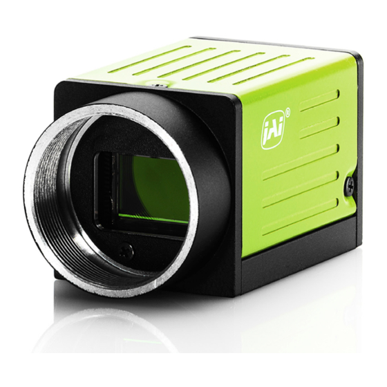
Page 8: Parts Identification
GO-2401M-PGE / GO-2401C-PGE Connection example: Camera PoE-compatible switching hub AC adapter External trigger Computer Parts Identification ② ⑤ ④ ③ ⑧ ① ⑥ ⑦ ⑧ 1 Lens mount (C-mount) Mount a C-mount lens, microscope adapter, etc. here. Before mounting a lens, be sure to refer to “Step 2: Connecting Devices” (page 13) and confirm the ™... - Page 9 GO-2401M-PGE / GO-2401C-PGE 2 RJ-45 connector Connect a Gigabit Ethernet compatible LAN cable (Category 5e or higher, Category 6 recommended) here. Input/ Pin No. Description output In/Out MX1+ (DA+) In/Out MX1– (DA–) In/Out MX2+ (DB+) In/Out MX3+ (DC+) In/Out MX3– (DC–) In/Out MX2–...
- Page 10 GO-2401M-PGE / GO-2401C-PGE Recommended external input circuit diagram (reference example) JAI camera User side User side GO Series CAMERA side BF545C +3.3V 180CS TLP2366 HIROSE_6Pin_No.2 USER POWER1 +3.3V to +24V HIROSE_6Pin_No.5 Recommended external output circuit diagram (reference example) Standard circuit diagram example...
- Page 11 GO-2401M-PGE / GO-2401C-PGE Characteristics of the recommended circuits for Opto OUT OUTPUT LINE RESPONSE TIME Camera Output Signal Output Line Voltage Output LEVEL = User Vcc- (0.8 to 1.1) 7 Camera locking screw holes (M3, 3 mm depth) Use these holes when attaching an MP-43 tripod adapter plate (optional) or mounting the camera directly to a wall or other structural system.
-
Page 12: Preparation
When using the camera for the first time, install the software for configuring and controlling the camera (eBUS SDK for JAI) on the computer. ❖ When you install eBUS SDK for JAI, eBUS SDK for JAI player will also be installed. Download the eBUS SDK for JAI from the JAI website. -
Page 13: Step 2: Connecting Devices
GO-2401M-PGE / GO-2401C-PGE Step 2: Connecting Devices Connect the lens, LAN cable, AC adapter, and other devices. Attach the lens in a clean environment to prevent dust from adhering to the unit. (or direct connection) Camera body 4 Network card... -
Page 14: Step 3: Verifying The Camera's Network Connection Status
GO-2401M-PGE / GO-2401C-PGE 3 LAN cable Connect a LAN cable to the RJ-45 connector. • Use a LAN cable that is Category 5e or higher (Category 6 recommended). • When supplying power via PoE, connect to a PoE-compatible switching hub or a PoE-compatible network card. -
Page 15: Step 4: Verifying The Connection Between The Camera And Pc
GO-2401M-PGE / GO-2401C-PGE Step 4: Verifying the Connection between the Camera and PC Verify whether the camera is properly recognized via eBUS Player for JAI. Connecting the Camera to eBUS Player for JAI. Startup eBUS Player for JAI eBUS Player for JAI startup screen appears. - Page 16 GO-2401M-PGE / GO-2401C-PGE Check that the settings of the selected camera are displayed. eBUS Player for JAI File Tools Help Connection Select / Connect Disconnect IP address MAC address GUID XXXXXXXXXXX Vendor JAI Corporation GO-2401C-PGE Model JAI_DEMO Name Acquisition Control...
-
Page 17: Step 5: Changing The Camera Settings
GO-2401M-PGE / GO-2401C-PGE Step 5: Changing the Camera Settings This section explains how to change settings by describing the procedure for changing the output format as an example. Configuring the Output Format Configure the size, position, and pixel format of the images to be acquired. - Page 18 GigE NIC or switch. To correct the problem, you can either reduce the [Packet Size] setting to a value less than 1500 in the JAI Control Tool (under [Transport Layer Control] / [Stream Channel Selector], or set your NIC or switch to support “Jumbo...
- Page 19 GO-2401M-PGE / GO-2401C-PGE Set [Exposure Mode] to [Timed]. ([Timed] is the default setting.) Specify the exposure time in [Exposure Time]. The setting value for the exposure time can only be changed when [Exposure Auto] is set to [Off]. If [Exposure Auto] is set to [Continuous], temporarily set it to [Off] before changing the exposure time.
- Page 20 GO-2401M-PGE / GO-2401C-PGE ■ Control Without External T riggers When Controlling the Exposure Time Using Specified Exposure Times Configure the settings as follows. Item Setting value / selectable range Trigger Selector (trigger operation) Frame Start Trigger Mode Exposure Mode Timed (control via exposure time) 1 to 7999730 (µs) (1 µs/step)*...
-
Page 21: Step 6: Adjusting The Image Quality
Expand [Analog Control], and select the gain you want to configure in [Gain Selector]. • For the GO-2401M-PGE, only [Analog All] (master gain) can be configured. • For the GO-2401C-PGE, [Analog All] (master gain), [Digital Red] (digital R gain), and [Digital Blue] (digital B gain) can be configured individually. -
Page 22: Step 7: Saving The Settings
Expand [Analog Control], and select the black level you want to configure in [Black Level Selector]. For the GO-2401M-PGE, only [Digital All] (master black) can be configured. For the GO-2401C-PGE, [Digital All] (master black), [Digital Red] (digital R), and [Digital Blue] (digital B) can be configured individually. - Page 23 GO-2401M-PGE / GO-2401C-PGE ■ To save user settings Stop image acquisition. Expand [User Set Control], and select the save destination ([User Set1] to [User Set3]) in [User Set Selector]. Note The factory default setting values are stored in [Default] and cannot be overwritten.
-
Page 24: Basic Function Matrix
2 × 1 × × × 2 × 2 × × × *1 Operates only on the GO-2401M-PGE *2 Operates only on the GO-2401C-PGE — 24 —... -
Page 25: Main Functions
GO-2401M-PGE / GO-2401C-PGE Main Functions GPIO (Digital Input/Output Settings) The camera is equipped with GPIO (general-purpose input/output) functions for generating and using combinations of triggers and other necessary signals within the camera and of signals output from the camera to the system such as those used for lighting equipment control. -
Page 26: Acquisition Control (Image Acquisition Controls)
GO-2401M-PGE / GO-2401C-PGE Acquisition Control (Image Acquisition Controls) Perform operations and configure settings related to image acquisition in [Acquisition Control]. The following acquisition modes are available on the camera. Acquisition Mode Description Single Frame Acquire a single frame when the [Acquisition Start] command is executed. -
Page 27: Maximum Frame Rate Period Formula
GO-2401M-PGE / GO-2401C-PGE ■ Maximum frame rate period formula During continuous operation ([Frame Start] trigger is [Off] or [Exposure Mode] is [Off]) • Maximum frame rate of sensor output SensorFR = 1 / ((Height_s + 40) × Hperiod) • Maximum frame rate of GigE output bandwidth InterfaceFR = 920 ×... -
Page 28: Exposure Mode
GO-2401M-PGE / GO-2401C-PGE Pixel Binning User settings Height_s* Height_g* Width_g* H period Pack Maximum Format value frame rate Height Width (fps) 8-bit B.V&B.H 1 1216 1936 1216 1216 1936 19.394 × 10 41.0 (Off) B.V 2 (On) 1936 1216 1936 41.0... -
Page 29: Trigger Control
GO-2401M-PGE / GO-2401C-PGE Trigger Control The camera allows the following controls to be performed via external trigger signals. Trigger Selector Description Frame Start Start exposure in response to the external trigger signal input. Select this to perform exposure control using external triggers. -
Page 30: When [Exposure Mode] Is [Timed]
GO-2401M-PGE / GO-2401C-PGE ■ When [Exposure Mode] is [Timed] Example: When [Trigger Source] is set to [Line 5 - Optical In 1] and [OptIn Filter Selector] is set to [10 µs] • Trigger overlap: Off Next trigger disabled Next trigger... -
Page 31: When [Exposure Mode] Is [Trigger Width]
GO-2401M-PGE / GO-2401C-PGE ■ When [Exposure Mode] is [Trigger Width] Example: When [Trigger Source] is set to [Line 5 - Optical In 1] and [OptIn Filter Selector] is set to [10 µs] • Trigger overlap: Off Next trigger disabled Next trigger... -
Page 32: Event Control
GO-2401M-PGE / GO-2401C-PGE Event Control “Event control” is a function that uses GVCP (GigE Vision Control Protocol) to output points of change in the camera’s internal signal as event occurrence information or “event messages.” When this information is output, the camera’s internal timestamp counter value is added. -
Page 33: To Use The Event Control Function
GO-2401M-PGE / GO-2401C-PGE ■ To use the event control function Configure the settings as follows. Item Setting value / selectable range Description Event Selector Acquisition Trigger, Select the event for which to send notifications. Frame Start, Frame End, FVAL Start,... -
Page 34: Lut (Lookup Table)
(Index 0) to the highest (Index 255). For example, Index 0 represents a full black pixel and Index 255 represents a full white pixel on the GO-2401M-PGE. LUT Value 0 to 4095 Set the LUT output value for the selected index. -
Page 35: Gamma Function
GO-2401M-PGE / GO-2401C-PGE 4095 Values between points are determined LUT Value [1] using the linear interpolation values of data to the left and right. LUT Value [0] Index0 Index255 Index1 Gamma Function The gamma function corrects the output signals from the camera beforehand (reverse correction), taking into consideration the light-emitting properties of the monitor display. -
Page 36: Line Status
GO-2401M-PGE / GO-2401C-PGE Line Status The line status function allows you to verify the status of external input/output signals. You can verify the status of the following signals. • Opt Out 1, Opt Out 2, Opt In 1 • Time Stamp Reset •... -
Page 37: Color Shading (Go-2401C-Pge Only)
GO-2401M-PGE / GO-2401C-PGE Within 30% of adjustment range ■ Color Shading (GO-2401C-PGE only) R-channel and B-channel properties are adjusted to using the G-channel shading properties as a reference. Pre-correction Post-correction Caution Proper correction is not possible under the following conditions. -
Page 38: Roi (Regional Scanning Function)
GO-2401M-PGE / GO-2401C-PGE ROI (Regional Scanning Function) The ROI (region of interest) function allows you to output images by specifying the areas to scan. ROI Settings Specify the area to scan by specifying width, height, and horizontal/vertical offset values under [Image Format Control]. -
Page 39: Video Send Mode
GO-2401M-PGE / GO-2401C-PGE Video Send Mode Switch the video transmission mode to configure and operate Multi ROI and Sequencer Mode. Video Send Mode ■ To switch the video send mode The video transmission mode is configured with the [Sequencer Mode], [Sequencer Mode Selector], and [Video Mode Selector] settings. -
Page 40: Multi Roi Mode
GO-2401M-PGE / GO-2401C-PGE ■ Multi ROI Mode In the multi ROI mode, you can specify up to five scanning areas (Index 1 to 5) for a single-frame image. On the GO-2401-PGE, the areas can overlap, and a separate frame will be output for each area. - Page 41 GO-2401M-PGE / GO-2401C-PGE Trigger Sequencer mode With this mode, the Sequencer Trigger “pattern” is predetermined by the user. The user defines up to 128 different “indexes.” Each index represents a combination of the following parameters: • ROI (width, height, offset X, and offset Y) •...
- Page 42 GO-2401M-PGE / GO-2401C-PGE Index structure for Trigger Sequencer Index Selector Exposure Black Next Frame Binning1 Gain1 Index1 ROI1 Level1 Enable1 Count1 Index1 (M/Red/Blue) (H/V) (MUX) Exposure Black Frame Next Gain2 Binning2 Index2 ROI2 Level2 Enable2 Count2 Index2 (M/Red/Blue) (H/V) Current...
-
Page 43: Delayed Readout [Acquisition Transfer Start]
GO-2401M-PGE / GO-2401C-PGE Command Sequencer Example User-defined Indexes (up to 128) Index1 Index2 Index3 Exposure Exposure Exposure Gain Gain Gain Binning Binning Binning Set to Set to Set to Set to Set to Set to Index1 Index1 Index3 Index1 Index2... -
Page 44: Alc (Automatic Level Control) Function
Set [Gain Auto] or [Exposure Auto] or both to [Continuous] mode. Configure the minimum value, maximum value, etc. for AGC and ASC under [JAI Custom Control ALC]. The target video levels for AGC and ASC are configured in [ALC Reference]. For example, when [ALC Reference] is set to 100%, video levels will be maintained at 100% for AGC and ASC. -
Page 45: Detailed Settings For Gain Auto (Automatic Gain Level Control)
GO-2401M-PGE / GO-2401C-PGE Detailed Settings for Gain Auto (Automatic Gain Level Control) When [Gain Auto] is set to [Continuous], you can configure the conditions for automatic adjustment in detail. Item Description ALC Reference Specify the target level for automatic gain control. (This setting is also used for automatic exposure control.) -
Page 46: Counter And Timer Control Function (Counter Support Only)
GO-2401M-PGE / GO-2401C-PGE Counter and Timer Control Function (counter support only) The counter function counts up change points in the camera’s internal signals using the camera’s internal counter, and reads that information from the host side. This function is useful for verifying error conditions via the count value using internal camera operations. -
Page 47: To Use The Counter Function
GO-2401M-PGE / GO-2401C-PGE ■ To use the counter function Configure the settings as follows. Three counters can be configured (Counter 0 to 2). Item Setting value / selectable range Description Counter 0 to 2 Counter 0 to 2 Select the counter. -
Page 48: Chunk Data Function
GO-2401M-PGE / GO-2401C-PGE Chunk Data Function The Chunk Data function adds camera configuration information to the image data that is output from the camera. Embedding camera configuration information in the image data allows you to use the serial number of the camera as a search key and find specific image data from among large volumes of image data. -
Page 49: Configuring Chunk Data
GO-2401M-PGE / GO-2401C-PGE ■ Configuring Chunk Data Set [Chunk Mode Active] to [True]. Select the itesms of information you want added to image data with [Chunk Selector], and set [Chunk Enable] from [False] to [True]. Note When [Chunk Mode Active] is set to [True], [Chunk Image] is automatically set to [True]. -
Page 50: Settings List
GO-2401M-PGE / GO-2401C-PGE Settings List Feature Properties : Settings that can only be configured when image acquisition on the camera is stopped. Item Setting range Default value Description Display/configure information related to a) Device Control the device. Device Vendor Name —... - Page 51 GO-2401M-PGE / GO-2401C-PGE Item Setting range Default value Description c) Acquisition Control Configure image acquisition settings. Acquisition Mode Single Frame, Multi Frame, Continuous Select the image acquisition mode. Continuous Acquisition Start — — Start image acquisition. Acquisition Stop — —...
- Page 52 Description Gamma 0.45, 0.60, 1.0 0.45 Set the gamma value. JAI LUT Mode Off, Gamma, LUT Select the JAI LUT mode. f) LUT Control Configure LUT settings. LUT Selector R, G, B Select the LUT channel to control. (GO-2401C-PGE only)
- Page 53 GO-2401M-PGE / GO-2401C-PGE Item Setting range Default value Description Configure settings for digital input/output. h) Digital IO Control Line Selector Line2 - Opt Out 1, Line2 - Opt Out 1 Select the input/output to configure. Line3 - Opt Out 2,...
- Page 54 GO-2401M-PGE / GO-2401C-PGE Item Setting range Default value Description Pulse Generator Selector Pulse Generator 0 Pulse Generator 0 Select the pulse generator. Pulse Generator Length 1 to 1048575 30000 Set the count-up value (clock value) for the pulse generator. Pulse Generator Length 0.002222 to 2330.166666...
- Page 55 GO-2401M-PGE / GO-2401C-PGE Item Setting range Default value Description Interface Selector — Set the interface. Mac Address — XX-XX-XX-XX- Display the MAC address. XX-XX Supported LLA — True Display whether LLA (link-local address) is supported. Supported DHCP — True Display whether DHCP is supported.
- Page 56 GO-2401M-PGE / GO-2401C-PGE Item Setting range Default value Description Timestamp Tick Value — Display the timestamp value. Control Channel Privilege — ControlAccess Display the control channel privilege. Message Channel Port 0 to 65535 XXXXX Set the port number for the message channel.
- Page 57 Shading Detect Result — — Display the shading detection results. When using the JAI Multi ROI function, set q) JAI Custom Control MultiROI the scanning area. Multi Roi Index Index 1 to 5 Index 1 Set the Multi ROI index table.
- Page 58 — Display the count value. Counter 0 to 2 Status — Counter Active Display the counter status. Configure settings for other JAI functions. s) JAI Custom control features Misc. Video Process Bypass On, Off Enable / disable video process bypass Mode mode.
-
Page 59: Miscellaneous
GO-2401M-PGE / GO-2401C-PGE Miscellaneous Troubleshooting Check the following before requesting help. If the problem persists, contact your local JAI distributor. ■ Power supply and connections Problem Cause and solution The power / trigger LED remains lit amber and Camera initialization may not be complete due to lack of a does not turn green, even after power is network connection. -
Page 60: Specifications
GO-2401M-PGE / GO-2401C-PGE Specifications Item GO-2401M-PGE GO-2401C-PGE Scanning system Progressive scan, 1 tap Synchronization Internal Interface 1000BASE-T Ethernet (GigE Vision 1.1), IEEE 802.3af Image sensor 1/1.2-inch monochrome CMOS 1/1.2-inch Bayer color CMOS Image size (effective image) 11.3 (H) × 7.13 (V), 13.4 mm diagonal Pixel size 5.86 (H) ×... - Page 61 GO-2401M-PGE / GO-2401C-PGE Item GO-2401M-PGE GO-2401C-PGE Black level Default level 33LSB (during 10-bit output) adjustment Video level adjustment range R/B: 20 to 60 (during 10-bit output) Adjustment range –33LSB to +64LSB against reference level (during 10-bit output) Resolution adjustment 1 STEP = 0.25LSB...
-
Page 62: Frame Rate Reference
GO-2401M-PGE / GO-2401C-PGE Frame Rate Reference (Theoretical value: decimal values are dropped, during Unpacked) Resolution Pixel count ROI/Binning Pixel size(μm) Image size Frame rate (screen size) 2.35 MP 1936 × 1216 Full pixel 5.86 × 5.86 1/1.2" (13.40 mm) 41.0 fps (@8 bit) 2 MP 1920 ×... -
Page 63: Dimensions
GO-2401M-PGE / GO-2401C-PGE GO-2401C-PGE 1000 wave length (nm) Dimensions 41.5 C Mount 12.5 23.7 4-M2 Depth3 3-M3 Depth3 Dimensional tolerance: ±0.3 mm Unit: mm — 63 —... -
Page 64: User's Record
Serial No. …………….. Firmware version. …………….. For camera revision history, please contact your local JAI distributor. Trademarks • GigE Vision is a registered trademark of AIA (Automated Imaging Association). • Microsoft and Windows are trademarks or registered trademarks of Microsoft Corporation in the United States and other countries. -
Page 65: Index
GO-2401M-PGE / GO-2401C-PGE Index 6-pin round 9 white balance 21 LAN cable 14 LED 9 AC adapter 14 Lens 13 Acquisition Control 26 Lens mount 8 acquisition modes 26 LINK LED 9 ACT LED 9 Lookup Table 34 Adjusting the Black Level 22... - Page 66 Revision history Revision Date Changes Feb. 2019 Add KC, actual exposure time eBUS SDK for JAI Jun. 2019 Feb. 2020 Add Note, binning mode cannot be used in video process bypass mode.
Need help?
Do you have a question about the GO-2401M-PGE and is the answer not in the manual?
Questions and answers