Advertisement
Advertisement

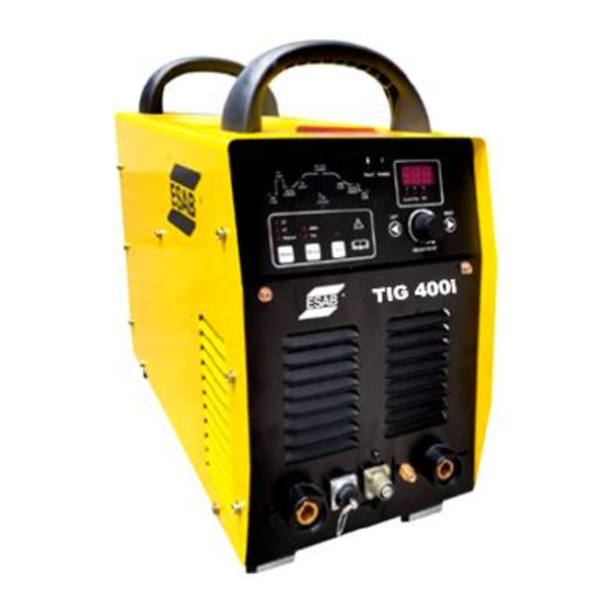
Summary of Contents for ESAB TIG 400i
- Page 1 TIG 400i INVERTER TIG Welding Power Source Instruction manual Ver:3.0 3220...
- Page 2 TIG 400i INVERTER WELDING POWER SOURCE Instruction manual Installation, Operation & General maintenance...
-
Page 3: Table Of Contents
CONTENTS Item Page No. SAFETY RATING AND INSTALLATION CAUTIONS FOR INSTALLATION WELDING OPERATIONS 9-11 WIRING DIAGRAM GENERAL MAINTENANCE PARTS LIST AND EXPLODED VIEW 14-17 ESAB INDIA CONTACT DETAIL... -
Page 4: Safety
SAFETY Users of ESAB welding equipment have the ultimate responsibility for ensuring that anyone who works on or near the equipment observes all the relevant safety precautions. Safety precautions must meet the requirements that apply to this type of welding equipment. The following recommendations should be observed in addition to the standard regulations that apply to the workplace. - Page 5 ESAB can provide you with all necessary welding protection and accessories. WARNING Arc welding and cutting can be injurious to yourself and others. Take precautions when welding. Ask for your employer’s safety practices which should be based on manufacturers’ hazard data.
- Page 6 RATING RATING OF TIG 400i INVERTER WELDING POWER SOURCE Contents of parameters Unit TIG 400i No-load voltage The working voltage of 20.4-36.0 manual welding The working voltage of 10.4-26.0 argon arc welding TIG: 400 Rated welding current MMA: 400 Output...
- Page 7 Three-phase Ground model current breaker input cable wire TIG 400i 415V ≥4 mm ≥4 mm 60 A Output connection The positive pole of the output end, the negative pole of the output end and the control connector (welding torch switch) are all located on the lower side of the front panel, please refer to the structure diagram of welding machine for details.
-
Page 8: Cautions For Installation
tighten it clockwise. Connect one end of the positive output cable to the positive quick coupling, and the other end to the electrode holder. Connect the positive quick coupling to the positive pole of the output end and tighten it clockwise. (2) Argon arc welding connection method Connect one end of the positive output cable to the positive quick coupling, and the other end to the job. - Page 9 b) Ventilation Adequate ventilation is recommended at the place of installation. For example the following guideline should be followed: a) In case of the area being more than 300 square meters (per unit), no ventilation is required, provided the room is not completely airtight. b) In case of the area being less than 300 square meters and the welding is continuously performed, adequate ventilation is recommended with the help of vent fan or exhaust duct.
-
Page 10: Welding Operations
WELDING OPERATIONS Front Panel Select the parameters to be adjusted by adjusting the LEFT or RIGHT shift keys on the front panel, and preset the parameters to be welded through the panel ADJUSTMENT knob. Each welding parameter on the front panel can be independently adjusted, and the ranges are as follows: Pre flow Gas Initial current... - Page 11 2- Step Mode Welding gun switch Solenoid value Discharging time 0.5s, stopped until there is current High-frequency discharge Arc starting current Welding current Up slope Welding current Arc starting current 0.3s Down slope Pre-flow time Post flow time Diagram of 2-step welding mode 4-Step Mode Welding gun switch...
- Page 12 Repeat Press torch within 1 second after releasing, arc die out Welding gun switch Solenoid value Discharging time 0.5s, stopped until there is current High-frequency discharge Arc starting current Up slope Welding current Welding Up slope Down slope current Crater current Initial current Pre-flow time Post flow time...
-
Page 13: Wiring Diagram
WIRING DIAGRAM... -
Page 14: General Maintenance
General maintenance No additional maintenance for fan is required as all parts of the fan are sealed. If the welding machine is used where there is a lot of dust, the dust may block the air duct of the welding machine and cause the welding machine to heat up. Therefore, it is necessary to use dry compressed air to remove the dust inside the welding machine at set intervals. -
Page 15: Parts List And Exploded View
Socket (plate-type) Air outlet nozzle 0061301356 Aviation socket (2-core) 0012001047 Aviation socket 0012001045 Welding cable coupling device 0050804024 Socket Display board TIG 400i 0030101983 Potentiometer knob (large) 0010603056 Two-position two-way solenoid 0011001003 valve Miniature circuit breaker 0011501003 Input cables 0030501596... - Page 16 Part Part Name Number Coupler 0030801612 Arc striking device (spark plug) 0012301292 High-frequency arc striking board 0030101746 High-frequency and high-voltage 0010227003 capacitor Current transformer 0011303019 IGBT module 0012101060 Filter capacitor 0010222014 Discharge resistor component 0030502252 Drive board 0030101747 Capacitor 0010227001 Three-phase input inductance 0031001147 Diode absorption board...
- Page 19 ESAB INDIA LIMITED Registered and Head Office 13, Industrial Estate, III Main Road Ambattur, Chennai - 600058 Telephone: + 91 44 42281100 Fax: + 91 44 4228 1107 Email: info@esab.co.in Web: www.esabindia.com...


Need help?
Do you have a question about the TIG 400i and is the answer not in the manual?
Questions and answers