Vicon Roughneck AI V2000D Series Quick Manual
Outdoor micro dome cameras
Hide thumbs
Also See for Roughneck AI V2000D Series:
- Quick manual (21 pages) ,
- Quick manual (20 pages)
Table of Contents
Advertisement
Quick Links
Quick Guide
Roughneck AI V2000D Series
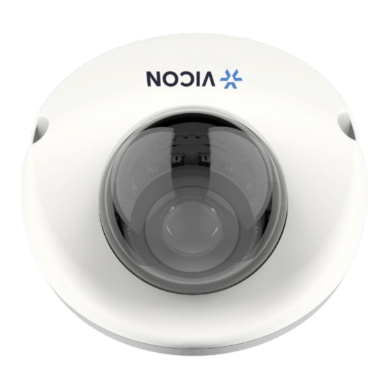
Outdoor Micro Dome Cameras
XX318-50-04
Cybersecurity Notification:
accessing the device. To that end, these network cameras do not have a default password. A user defined
password with minimum password strength requirements must be set to access the device. See page 14 of
this Quick Guide for set-up instructions.
Be sure to check Vicon's website to be see if you have the most up-to-date camera firmware
Vicon Industries Inc. does not warrant that the functions contained in this equipment will
meet your requirements or that the operation will be entirely error free or perform precisely as
described in the documentation. This system has not been designed to be used in
life-critical situations and must not be used for this purpose.
Document Number: 8009-8318-50-04 Product specifications subject to change without notice.
Issued: 2/2023 Copyright © 2023 Vicon Industries Inc. All rights reserved.
All network connected devices should use best practices for
Vicon Industries Inc.
Tel: 631-952-2288) Fax: 631-951-2288
Toll Free: 800-645-9116
24-Hour Technical Support: 800-34-VICON
UK: 44/(0) 1489-566300
www.vicon-security.com
(800-348-4266)
Advertisement
Table of Contents

Related Manuals for Vicon Roughneck AI V2000D Series


Summary of Contents for Vicon Roughneck AI V2000D Series
- Page 1 See page 14 of this Quick Guide for set-up instructions. Be sure to check Vicon’s website to be see if you have the most up-to-date camera firmware Vicon Industries Inc.
-
Page 2: Table Of Contents
Quick Guide Table of Content Product Overview Physical Characteristics Installation and Connection Package Contents Installation 2.2.1 Checking Appearance 2.2.2 Disassembling the Camera 2.2.3 Mounting the Camera 2.2.4 Connecting the Cables 2.2.5 PoE Port & Waterproof Connector (IWPWPC) Wiring Procedure 2.2.6 Positioning the Camera 2.2.7 Securing Desiccant... - Page 3 Micro Dome Quick Guide WARNING This camera operates at PoE (IEEE 802.3af Class 3). Installation and service should be performed only by qualified and experienced technicians and comply with all local codes and rules to maintain your warranty. We are NOT liable of any damage arising either directly or indirectly from inappropriate installation which ...
- Page 4 Quick Guide FCC Compliance Statement Information to the user: This unit has been tested and found to comply with the limits for a Class B digital device pursuant to Part 15 of the FCC Rules. Operation is subject to the following two conditions: (1) this device may not cause harmful interference, and (2) this device must accept any interference received, including interference that may cause undesired operation.
-
Page 5: Product Overview
Micro Dome Quick Guide 1 Product Overview 1.1 Physical Characteristics Figure 1 - 1: Physical Dimension Unit: mm (in.) - Page 6 Quick Guide Figure 1 - 2: Parts Pictorial Index...
- Page 7 Micro Dome Quick Guide Name Description Camera Housing Top cover of the camera. Screws of Camera Housing Screws for fixing Camera Housing to Camera Bottom Case. Bottom base of the camera. Camera Bottom Case IR LED embedded board for illumination under low-light IR Board environment.
-
Page 8: Installation And Connection
Quick Guide 2 Installation and Connection Package Contents Check if all items listed below are included in the packing box. Fixed Flat Dome Camera * 1 Plastic Anchor * 2 Pan Head Screw (Tapping Type) * 2 Security Torx Bit (T20) * 1 ... -
Page 9: Mounting The Camera
Micro Dome Quick Guide Figure 2 - 1: Disassembling the Camera 2.2.3 Mounting the Camera 1. Attach the mounting template to the wall or ceiling. 2. Drill two holes indicated on the mounting template and insert the supplied plastic anchors into the holes. 3. -
Page 10: Connecting The Cables
Quick Guide ① Mounting Template ② Plastic Anchors * 2 ③ Pan Head Screws (TP4) * 2 Figure 2 - 2: Mounting the Camera 2.2.4 Connecting the Cables 1. PoE (Class 3): Connect an Ethernet cable terminated with RJ-45 connector to the PoE RJ-45 port for both power supply and network connectivity purposes. -
Page 11: Positioning The Camera
Micro Dome Quick Guide ① Waterproof ② Ethernet Cable Connector ③ RJ-45 Connector ④ Rubber O-Ring ⑤ PoE Port Figure 2 - 3: Waterproof Connector Wiring 2.2.6 Positioning the Camera Pan Adjustment (A) Rotate the lens camera assembly to the desired field of view. Horizontal Rotation (B) ... -
Page 12: Securing Desiccant
Quick Guide 2.2.7 Securing Desiccant 1. Remove the desiccant from the package. 2. Flip over the camera housing and apply desiccant to the circle recess, as shown in the figure below. NOTE: Be sure to apply the desiccant before camera assembly to avoid fogging. Figure 2 - 5: Securing Desiccant 2.2.8 Reassembling the Camera 1. -
Page 13: Connection
Micro Dome Quick Guide 3 Connection Network The camera, which is equipped with Ethernet RJ-45 network interface, can deliver live view image in real time via both Internet and Intranet manners. System Requirements The table below lists the minimum requirement to implement and operate the camera. It is recommended not to use any hardware/software component below these requirements for proper performance. -
Page 14: Connecting Process
The camera can be accessed directly from its web page or using Vicon’s PRONTO Device Manager, which can be found on Vicon’s website. Note that when accessing the camera for the first time, a message will display to reset the password. - Page 15 Micro Dome Quick Guide PRONTO Device Manager PRONTO is Vicon’s device manager (Discovery tool) that can be used to discover all Vicon cameras on a system. The complete User Manual can be found on Vicon’s website. Figure 3 - 2: PRONTO Interface Upon startup of the PRONTO Device Manager, the tool’s auto-discovery function generates a list of...
Need help?
Do you have a question about the Roughneck AI V2000D Series and is the answer not in the manual?
Questions and answers