Table of Contents
Advertisement
Advertisement
Table of Contents

Related Manuals for MPP Solar 3KW


Summary of Contents for MPP Solar 3KW
- Page 1 User Manual 3KW/5KW PIP-MK SERIES INVERTER / CHARGER Version: 1.0...
-
Page 2: Table Of Contents
Table Of Contents ABOUT THIS MANUAL ............................1 Purpose ................................1 Scope ................................1 SAFETY INSTRUCTIONS ........................... 1 INTRODUCTION ..............................2 Features ................................2 Basic System Architecture ..........................2 Product Overview ............................. 3 INSTALLATION ..............................4 Unpacking and Inspection..........................4 Preparation .............................. -
Page 3: About This Manual
ABOUT THIS MANUAL Purpose This manual describes the assembly, installation, operation and troubleshooting of this unit. Please read this manual carefully before installations and operations. Keep this manual for future reference. Scope This manual provides safety and installation guidelines as well as information on tools and wiring. SAFETY INSTRUCTIONS WARNING: This chapter contains important safety and operating instructions. -
Page 4: Introduction
INTRODUCTION This is a multi-function inverter/charger, combining functions of inverter, MPPT solar charger and battery charger to offer uninterruptible power support with portable size. Its comprehensive LCD display offers user-configurable and easy-accessible button operation such as battery charging current, AC/solar charger priority, and acceptable input voltage based on different applications. -
Page 5: Product Overview
Product Overview 1. LCD display 2. Status indicator 3. Charging indicator 4. Fault indicator 5. Function keys (Please refer to operation chapter for the detailed operation) 6. Power on/off switch 7. AC input 8. AC output 9. PV input 10. Battery input 11. -
Page 6: Installation
INSTALLATION Unpacking and Inspection Before installation, please inspect the unit. Be sure that nothing inside the package is damaged. You should have received the following items inside of package: The unit x 1 User manual x 1 Communication cable x 1 ... -
Page 7: Battery Connection
2. Connect all battery packs as units requires. It’s suggested to connect at least 200Ah capacity battery for 3KW model and at least 200Ah capacity battery for 5KW model. 3. Insert the ring terminal of battery cable flatly into battery connector of inverter and make sure the bolts are tightened with torque of 2-3 Nm. -
Page 8: Ac Input/Output Connection
AC input power source. This will ensure the inverter can be securely disconnected during maintenance and fully protected from over current of AC input. The recommended spec of AC breaker is 30A for 3KW, 50A for 5KW. CAUTION!! There are two terminal blocks with “IN” and “OUT” markings. Please do NOT mis-connect input and output connectors. -
Page 9: Pv Connection
WARNING: Be sure that AC power source is disconnected before attempting to hardwire it to the unit. 4. Then, insert AC output wires according to polarities indicated on terminal block and tighten terminal screws. Be sure to connect PE protective conductor ( ) first. -
Page 10: Final Assembly
PV Module Selection: When selecting proper PV modules, please be sure to consider below parameters: 1. Open circuit Voltage (Voc) of PV modules not exceeds max. PV array open circuit voltage of inverter. 2. Open circuit Voltage (Voc) of PV modules should be higher than min. battery voltage. Solar Charging Mode INVERTER MODEL 145Vdc... -
Page 11: Remote Display Panel Installation
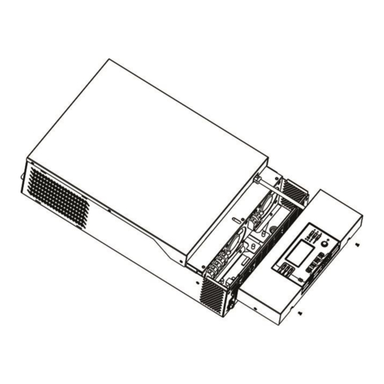
Remote Display Panel Installation The LCD panel can be removable and installed in a remote site with an optional communication cable. Please follow below steps to implement this remote panel installation. Step 1. Loosen the screw on the two sides of bottom case and push up the case cover. Then, remove screw on the top of the display panel. -
Page 12: Communication Connection
Communication Connection Serial Connection Please use supplied communication cable to connect to inverter and PC. Insert bundled CD into a computer and follow on-screen instruction to install the monitoring software. For the detailed software operation, please check user manual of software inside of CD. Bluetooth Connection This series is built in Bluetooth technology. -
Page 13: Operation
OPERATION Power ON/OFF Once the unit has been properly installed and the batteries are connected well, simply press On/Off switch (located on the button of the case) to turn on the unit. Operation and Display Panel The operation and display panel, shown in below chart, is on the front panel of the inverter. It includes three indicators, four function keys and a LCD display, indicating the operating status and input/output power information. -
Page 14: Lcd Display Icons
LCD Display Icons Icon Function description Input Source Information Indicates the AC input. Indicates the PV input Indicate input voltage, input frequency, PV voltage, charger current, charger power, battery voltage. Configuration Program and Fault Information Indicates the setting programs. Indicates the warning and fault codes. Warning: flashing with warning code. - Page 15 1.892V/cell ~ 1.975V/cell 1.975V/cell ~ 2.058V/cell > 2.058V/cell Load Information Indicates overload. Indicates the load level by 0-24%, 25-49%, 50-74% and 75-100%. 0%~24% 25%~49% 50%~74% 75%~100% Mode Operation Information Indicates unit connects to the mains. Indicates unit connects to the PV panel. Indicates load is supplied by utility power.
-
Page 16: Lcd Setting
LCD Setting ” After pressing and holding “ button for 3 seconds, the unit will enter setting mode. Press “ ” or “ ” button to select setting programs. And then, press “ ” button to confirm the selection or “ ”... - Page 17 60A (default) 3KW model setting range is from Maximum charging current: 10A to 120A and increment of To configure total charging each click is 10A. current for solar and utility 5KW model setting range is from chargers. 10A to 140A and increment of (Max.
- Page 18 “SBU” (SBU priority) or “SUB” (Solar 3KW model setting range is from 22.0V to 28.5V and increment of first) in program 01 each click is 0.5V. 5KW model setting range is from 44.0V to 57.0V and increment of each click is 1.0V.
- Page 19 5KW model: The setting range is from 48.0V to 64.0V and increment of each click is 1.0V. Setting voltage point back Battery fully charged 54.0V (default) to battery mode when selecting “SBU” (SBU priority) or “SUB” (Solar first) in program 01 SbL: Solar energy for Solar energy charges battery first battery first...
- Page 20 Return to default display If selected, no matter how users screen (default) switch display screen, it will automatically return to default display screen (Input voltage /output voltage) after no button is pressed for 1 minute. Auto return to default display screen Stay at latest screen If selected, the display screen will stay at latest screen user finally...
- Page 21 (C.V voltage) If self-defined is selected in program 5, this program can be set up. Setting range is from 24.0V to 32.0V for 3KW model and 48.0V to 64.0V for 5KW model. Increment of each click is 0.1V. 3KW default setting: 27.0V 5KW default setting: 54.0V...
- Page 22 3KW default setting: 29.2V 5KW default setting: 58.4V Battery equalization voltage Setting range is from 24.0V to 32.0V for 3KW model and 48.0V to 64.0V for 5KW model. Increment of each click is 0.1V. 60min (default) Setting range is from 5min to 900min.
- Page 23 For minute setting, the range is from 00 to 59. Time setting – Minute For hour setting, the range is from 00 to 23. Time setting – Hour For day setting, the range is from 00 to 31. Time setting– Day For month setting, the range is from 01 to 12.
-
Page 24: Display Setting
Display Setting The LCD display information will be switched in turns by pressing “ ” or “ ” button. The selectable information is switched as below order: input voltage, input frequency, PV voltage, charging current, charging power, battery voltage, output voltage, output frequency, load percentage, load in Watt, load in VA, load in Watt, DC discharging current, main CPU Version. - Page 25 AC and PV charging current=50A PV charging current=50A Charging current AC charging current=50A AC and PV charging power=500W PV charging power=500W Charging power AC charging power=500W Battery voltage=25.5V, output voltage=230V Battery voltage and output voltage...
- Page 26 Output frequency=50Hz Output frequency Load percent=70% Load percentage When connected load is lower than 1kVA, load in VA will present xxxVA like below chart. Load in VA When load is larger than 1kVA (≧1KVA), load in VA will present x.xkVA like below chart. When load is lower than 1kW, load in W will present xxxW like below chart.
- Page 27 PV energy generated Today = 3.88kWh, Load output energy Today = 9.88kWh. PV energy generated today and Load output energy today PV energy generated this month = 388kWh, Load output energy this month = 988kWh. PV energy generated this month and Load output energy this month.
- Page 28 Main CPU version 00014.04. Main CPU version checking. Secondary CPU version 00003.03. Secondary CPU version checking. Bluetooth version 00003.03. Bluetooth version checking. SCC version 00003.03. SCC version checking...
-
Page 29: Operating Mode Description
Operating Mode Description Operation mode Description LCD display Charging by utility and PV energy. Charging by utility. Standby mode Note: No output is supplied by the *Standby mode: The inverter unit but it still can charge is not turned on yet but at this batteries. - Page 30 Charging by utility The unit will provide output power from the utility. PV Bypass/ECO Mode energy and utility can charge No charging batteries. Charging by utility and PV energy. The unit will provide output power from the mains. It will Line Mode also charge the battery at Charging by utility.
-
Page 31: Fault Reference Code
Fault Reference Code Fault Code Fault Event Icon on Fan is locked when inverter is off. Over temperature Battery voltage is too high Battery voltage is too low Output short circuited or over temperature is detected by internal converter components. Output voltage is too high. -
Page 32: Battery Equalization
Battery Equalization Equalization function is added into charge controller. It reverses the buildup of negative chemical effects like stratification, a condition where acid concentration is greater at the bottom of the battery than at the top. Equalization also helps to remove sulfate crystals that might have built up on the plates. If left unchecked, this condition, called sulfation, will reduce the overall capacity of the battery. - Page 33 However, in Equalize stage, when battery equalized time is expired and battery voltage doesn’t rise to battery equalization voltage point, the charge controller will extend the battery equalized time until battery voltage achieves battery equalization voltage. If battery voltage is still lower than battery equalization voltage when battery equalized timeout setting is over, the charge controller will stop equalization and return to float stage.
-
Page 34: Specifications
SPECIFICATIONS Table 1 Line Mode Specifications INVERTER MODEL Input Voltage Waveform Sinusoidal (utility or generator) Nominal Input Voltage 230Vac Low Loss Voltage 110Vac± 7V Low Loss Return Voltage 120Vac± 7V High Loss Voltage 280Vac± 7V High Loss Return Voltage 270Vac± 7V Max AC Input Voltage 300Vac Nominal Input Frequency... -
Page 35: Table 2 Battery Mode Specifications
Table 2 Battery Mode Specifications INVERTER MODEL 3KVA/3KW 5KVA/5KW Rated Output Power Pure Sine Wave Output Voltage Waveform 230Vac± 5% Output Voltage Regulation 50Hz or 60Hz Output Frequency Peak Efficiency Overload Protection 5s@≥150% load; 10s@105%~150% load 2* rated power for 5 seconds... -
Page 36: Table 3 Charge Mode Specifications
Table 3 Charge Mode Specifications Utility Charging Mode INVERTER MODEL Charging Current Default: 30A, max: 60A @ Nominal Input Voltage Flooded 29.2Vdc 58.4Vdc Bulk Battery Charging AGM / Gel Voltage 28.2Vdc 56.4Vdc Battery Floating Charging Voltage 27Vdc 54Vdc Overcharge Protection 34Vdc 66Vdc Charging Algorithm... -
Page 37: Table 4 Eco/Bypass Mode Specifications
Table 4 ECO/Bypass Mode Specifications Bypass Mode INVERTER MODEL Input Voltage Waveform Sinusoidal (utility or generator) Low Loss Voltage 176Vac± 7V Low Loss Return Voltage 186Vac± 7V High Loss Voltage 280Vac± 7V High Loss Return Voltage 270Vac± 7V Nominal Input Frequency 50Hz / 60Hz (Auto detection) Low Loss Frequency 46(56)±... -
Page 38: Trouble Shooting
TROUBLE SHOOTING Problem LCD/LED/Buzzer Explanation / Possible cause What to do Unit shuts down LCD/LEDs and buzzer automatically will be active for 3 The battery voltage is too low 1. Re-charge battery. during startup seconds and then (<1.91V/Cell) 2. Replace battery. process. -
Page 39: Appendix I: Approximate Back-Up Time Table
Appendix I: Approximate Back-up Time Table Model Load (VA) Backup Time @24Vdc 200Ah (min) Backup Time @24Vdc 400Ah (min) 2200 1050 1200 1500 1800 2100 2400 2700 3000 Model Load (VA) Backup Time @ 48Vdc 200Ah (min) Backup Time @ 48Vdc 400Ah (min) 1226 2576 1000...
Need help?
Do you have a question about the 3KW and is the answer not in the manual?
Questions and answers