Advertisement
General Description
The MAX49918 evaluation kit (EV kit) is a fully tested and
assembled circuit that demonstrates the capabilities of
the MAX49918, a high-precision, wide measurement
range, programmable gain, bidirectional current-sense
amplifier that monitors two distinct current levels.
The gain of MAX49918 is programmed by I2C
communication.
The MAX49918 EV kit operates over the automotive
temperature range of -40°C to +125°C.
The EV kit reserves a PCB footprint so that a
MAX32625PICO board can be soldered on it. With the
MAX32625PICO board, users can control the gain
conveniently with the GUI software.
Features
•
Programmable Gain Options through I2C from 10V/V
to 200V/V (8 steps)
•
±1μV (typ) Input Offset Voltage for REF1 = REF2 =
VDD/2
•
±5μV (typ) Input Offset Voltage for REF1 = VDD and
REF2 = GND for Gain = 20V/V
•
±0.01% (typ) Gain Error
•
-5V to +70V Input Voltage Range
•
-6V to +80V Protective Immunity
•
70kHz, -3dB Bandwidth for Gain = 20V/V
•
145dB DC CMRR
•
Rail-to-Rail Output
•
3mm x 3mm TDFN-10 Package
•
-40°C to +125°C Temperature Range
MAX49918 EV Kit Files
FILE
max49918_tdfn10_evkit_a_
MARKETING_SCH.pdf
MAX49918_TDFN10_EVKIT_A
_MARKETING_PCB.PDF
marketing_bom_max49918_tdf
n10_evkit_a.csv
max49918_tdfn10_evkit_a.brd
Ordering Information
appears at end of data sheet.
Windows is a registered trademark and registered service mark
of Microsoft Corporation.
319-101014; Rev 0; 7/23
O n e A n a l o g W a y , W i l m i n g t o n , M A 0 1 8 8 7 - 2 3 5 6 , U . S . A .
EVAL-MAX49918 Evaluation Kit
DESCRIPTION
EV Kit Schematic
EV Kit PCB Layout
EV Kit Bill of Materials
EV Kit PCB Layout file
DOCUMENT FEEDBACK
T e l : 7 8 1 . 3 2 9 . 4 7 0 0
Evaluation Board User Guide
Quick Start
Required Equipment
•
MAX49918 EV kit
•
0 to 70V DC power supply for VCM input
•
+3.3V, 100mA DC power supply
•
Electronic load capable of sinking 3A
•
One 6½ digital multimeter (DMM like 34401A)
•
One 8½ digital multimeter (DMM like Agilent 3458)
Optional Equipment
•
MAX32625PICO Board
•
®
Windows
10 PC
•
MAX49918EV kit GUI software
Procedure
The MAX49918 EV kit is fully assembled and tested.
Follow the steps to verify board operation: Caution: Do not
turn on the power supply or the electronic load until all the
connections are complete.
1. Connect a +3.3V power supply to the VDD connector,
and the ground of this power supply to the GND
connector.
2. Connect the positive terminal of the 0 to 100V DC
(VCM) power supply to the VSENSE+ input and the
negative terminal to the GND connector.
3. Set the VCM power supply to 50V.
4. Set the electronic load to sink 300mA.
5. Connect the positive terminal of the electronic load to
the VSENSE- input and the negative terminal of the
electronic load to the GND of the VCM power supply.
6. Connect REF1 to REF2.
7. Connect the positive terminal of the DC power supply
to the REF1/REF2 input. Set the DC power supply
voltage output to VDD/2 = 1.65V.
8. Connect the 8½ digital multimeter between the test
points RS+ and RS- to measure the differential input
voltage across the inputs (VSENSE).
9. Connect the 6½ digital multimeter across the VOUT
and REF1/REF2 test points to measure the MAX49918
output.
10. Turn on the power supplies, then the electronic load.
11. Enable the electronic load.
12. Verify that the 8½ digital multimeter displays 300mA x
50mΩ = +15mV and the 6½ digital multimeter displays
150mV.
13. The EV kit is now ready for further testing.
14. After the functions are verified, do not forget to turn off
the electronic load, calibrator, and power supply.
© 2 0 2 3 A n a l o g D e v i c e s , I n c . A l l r i g h t s r e s e r v e d .
Evaluates: MAX49918
TECHNICAL SUPPORT
Advertisement
Table of Contents

Related Manuals for Analog Devices EVAL-MAX49918


Summary of Contents for Analog Devices EVAL-MAX49918
- Page 1 Evaluation Board User Guide EVAL-MAX49918 Evaluation Kit Evaluates: MAX49918 General Description Quick Start The MAX49918 evaluation kit (EV kit) is a fully tested and Required Equipment assembled circuit that demonstrates the capabilities of • MAX49918 EV kit the MAX49918, a high-precision, wide measurement •...
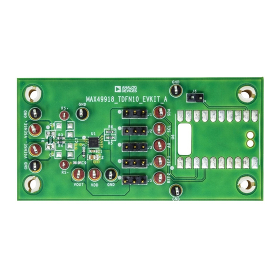
- Page 2 MAX49918 Evaluation Kit Evaluation Board User Guide EV Kit Photo Table 1. Jumper Connection Guide JUMPER DEFAULT CONNECTION FEATURE Not Installed Not Installed Set the least bit of I2C device address to 0 Set the least bit of I2C device address to 1 Connect REF1 to VDD Connect REF1 to GND Connect REF2 to GND...
-
Page 3: Gain Control
MAX49918 Evaluation Kit Evaluation Board User Guide Gain Control To set the gain of the device, it is recommended to use the PICO board (MAX32625PICO board) and MAX49918EV kit GUI software to control the gain. Or you need to use other devices or instruments to send I C command to the MAX49918. -
Page 4: Output Voltage
MAX49918 Evaluation Kit Evaluation Board User Guide I2C Address and data for Gain control If the user wants to send I2C with another method, check the below I2C address and data. The MAX49918 uses an input pin (A0) that determines the least-significative bit (LSB) of the I2C device address word below. - Page 5 HOLE=0.04IN; RED; PHOSPHOR BRONZE WIRE SILVER PLATE FINISH; BI-DIRECTIONAL WIDE MEASUREMENT RANGE WITH MAX49 PROGRAMMABLE GAIN CURRENT SENSE AMPLIFIER; PACKAGE MAX49918IATB+ ANALOG DEVICES OUTLINE: 21-0137; PACKAGE LAND PATTERN DRAWING: 90-0003; TDFN10-EP MAX49918TDFN10 MAXIM PCB:MAX49918TDFN10 1000P C3, C4, C7 C1206C102K1RAC KEMET CAP;...
- Page 6 MAX49918 Evaluation Kit Evaluation Board User Guide MAX49918 EV Kit Schematic analog.com Rev. 0 6 of 8...
-
Page 7: Revision History
MAX49918 Evaluation Kit Evaluation Board User Guide MAX49918 EV Kit PCB Layout MAX49918 EV Kit Component Placement Guide—Top MAX49918 EV Kit PCB Layout—Top Silkscreen MAX49918 EV Kit PCB Layout—Bottom MAX49918 EV Kit PCB Layout—Bottom Silkscreen Revision History REVISION REVISION PAGES DESCRIPTION NUMBER DATE... - Page 8 Evaluation Board User Guide ASSUMED BY ANALOG DEVICES FOR ITS USE, NOR FOR ANY INFRINGEMENTS OF PATENTS OR OTHER RIGHTS OF THIRD PARTIES THAT MAY RESULT FROM ITS USE. SPECIFICATIONS ARE SUBJECT TO CHANGE WITHOUT NOTICE. NO LICENCE, EITHER EXPRESSED OR...
Need help?
Do you have a question about the EVAL-MAX49918 and is the answer not in the manual?
Questions and answers