Table of Contents
Advertisement
Quick Links
Advertisement
Table of Contents
Troubleshooting

Related Manuals for Supermicro SuperServer AS-3015A-I


Summary of Contents for Supermicro SuperServer AS-3015A-I
- Page 1 SuperServer ® AS -3015A-I USER’S MANUAL Revision 1.0...
- Page 2 State of California, USA. The State of California, County of Santa Clara shall be the exclusive venue for the resolution of any such disputes. Supermicro's total liability for all claims will not exceed the price paid for the hardware product.
- Page 3 I f y o u h a v e a n y q u e s t i o n s , p l e a s e c o n t a c t o u r s u p p o r t t e a m a t : support@supermicro.com This manual may be periodically updated without notice. Please check the Supermicro website for possible updates to the manual revision level.
-
Page 4: Table Of Contents
Preface Contents Contacting Supermicro ......................7 Chapter 1 Introduction 1.1 Overview ..........................8 1.2 System Features ........................9 Front View ...........................9 Control Panel .........................10 Rear View ..........................11 Side View ..........................12 1.3 Motherboard Layout ......................13 Quick Reference Table ......................14 System Block Diagram ......................15 Chapter 2 Server Installation 2.1 Overview ..........................16... - Page 5 Preface 3.6 Motherboard Battery ......................33 3.7 Storage Drives ........................34 Installing Components in the 5.25" Drive Bays .............36 Removing the Empty Drive Bay ..................36 Adding a DVD-ROM Drive (optional)................36 3.8 System Cooling ........................37 Replacing the rear System Fan ..................37 3.9 Power Supply ........................38 Chapter 4 Motherboard Connections 4.1 Power Connections ......................39 4.2 Headers and Connectors ....................40...
- Page 6 7.5 Feedback ..........................66 7.6 Frequently Asked Questions ....................67 7.7 Battery Removal and Installation ..................68 Battery Removal ........................68 Proper Battery Disposal ....................69 Battery Installation ......................69 7.8 Contacting Supermicro .......................70 Appendix A Standardized Warning Statements for AC Systems Appendix B System Specifications BSMI/RoHS ..........................93...
-
Page 7: Contacting Supermicro
San Jose, CA 95131 U.S.A. Tel: +1 (408) 503-8000 Fax: +1 (408) 503-8008 Email: marketing@supermicro.com (General Information) Sales-USA@supermicro.com (Sales Inquiries) Government_Sales-USA@supermicro.com (Gov. Sales Inquiries) support@supermicro.com (Technical Support) RMA@supermicro.com (RMA Support) Webmaster@supermicro.com (Webmaster) Website: www.supermicro.com Europe Address: Super Micro Computer B.V. -
Page 8: Chapter 1 Introduction
Mini-tower, 14.3 x 7.3 x 16.8 in. / 362 x 184 x 425 mm (H x W x D) Notes: A Quick Reference Guide can be found on the product page of the Supermicro website. The following safety models associated with the AS -3015A-I have been certified as compliant with UL or CSA: 731-S6H13 and 731-6. -
Page 9: System Features
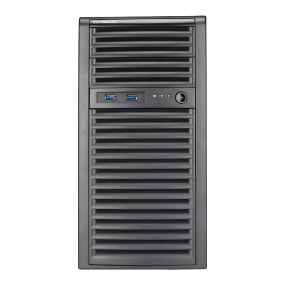
Chapter 1: Introduction 1.2 System Features The following views of the system display the main features. Refer to Appendix B for additional specifications. Front View 5.25" Drive Bays Control Panel Front Cooling Fan Figure 1-1. Front View System Features: Front Feature Description Control Panel... -
Page 10: Control Panel
Chapter 1: Introduction Control Panel Power Button Drive Activity LED USB3.2 Port USB3.2 Port Information LED NIC (LAN1) LED Figure 1-2. Control Panel Control Panel Features Feature Description The main power switch is used to apply or remove power from the power supply to the server. -
Page 11: Rear View
Chapter 1: Introduction Rear View Power Supply Rear I/O Ports PCIe Expansion Slots Figure 1-3. System: Rear View System Features: Rear Feature Description Power Supply One PS2 668 W 80Plus Platinum level power supply Rear Exhaust Fan One 9-cm PWM rear exhaust fan Rear I/O Backpanel For details, see 4.3 Input/Output... -
Page 12: Side View
Chapter 1: Introduction Side View 668 W Power Supply Two 5.25" Drive Bays DDR5 UDIMM Rear Exhaust Fan Four Internal 3.5" Drive Bays CPU Heatsink (optional) PCIe 5.0 x16 (16/NA or 8/8) PCIe 5.0 x8 M.2-C1 / C2 Front Cooling Fan Figure 1-4. -
Page 13: Motherboard Layout
Chapter 1: Introduction 1.3 Motherboard Layout Below is a layout of the H13SAE-MF motherboard with jumper, connector, and LED locations shown. See the table on the following page for descriptions. For detailed descriptions, pinout information, and jumper settings, refer to Chapter 4 or the Motherboard Manual. -
Page 14: Quick Reference Table
Chapter 1: Introduction Quick Reference Table Jumper Description Default Setting JBT1 CMOS Clear Open (Normal) UID SW Unit ID Switch (Push-Button Toggle Switch ON/OFF) JPG1 VGA Enable Pins 1-2 (Enabled) JWD1 Watch Dog Control Pins 1-2 (Reset) JUBUD1 BIOS Update Description Status LED1... -
Page 15: System Block Diagram
Chapter 1: Introduction System Block Diagram The block diagram below shows the connections and relationships between the subsystems and major components of the overall system. AMD SVI3 6 PHASE For VDDCR_CPU For 170 W #B-2 #B-1 #A-2 HDMI DDI1 #A-1 CH A DDR5 Raphael... -
Page 16: Chapter 2 Server Installation
Chapter 2: Workstation Installation Chapter 2 Server Installation 2.1 Overview This chapter provides advice setting up your system. If your system is not already fully integrated with processors, system memory etc., refer to Chapter 4 for details on installing those specific components. Caution: Electrostatic Discharge (ESD) can damage electronic components. -
Page 17: Server Precautions
Chapter 2: Workstation Installation Server Precautions • Review the electrical and general safety precautions in Appendix • Use a regulating uninterruptible power supply (UPS) to protect the server from power surges, voltage spikes and to keep your system operating in case of a power failure. •... -
Page 18: Chapter 3 Maintenance And Component Installation
Chapter 3: Maintenance and Component Installation Chapter 3 Maintenance and Component Installation This chapter provides instructions on installing and replacing main system components. To prevent compatibility issues, only use components that match the specifications and/or part numbers given. Installation or replacement of most components requires that power first be removed from the system. -
Page 19: Accessing The System
Chapter 3: Maintenance and Component Installation 3.2 Accessing the System The CSE-731I-668B chassis features a removable side cover for accessing the system need to remove power from the system as described in Section 3.1, and front cover which allows easy access to the inside of the chassis. Caution: Except for short periods of time, do not operate the system without the cover in place. - Page 20 Chapter 3: Maintenance and Component Installation Removing the Side Cover 1. Remove power from the system as described in Section 3.1. 2. Slide the latch (A) to the handle (B) of the chassis cover. 3. Grasp the handle of the case cover and slide it toward the back of the case. 4.
- Page 21 Chapter 3: Maintenance and Component Installation Opening the Front Cover The front bezel cover can be removed to install up to two peripheral drive bays at the front of the chassis. 1. Remove the front bezel from the chassis by lifting it upwards from the bottom, and then pulling out from the front of the chassis.
-
Page 22: Processor And Heatsink Installation
Thermal grease is pre-applied on a new heatsink. No additional thermal grease is needed. • Refer to the Supermicro website for updates on processor support. • All graphics in this manual are for illustrative purposes only. Your components may look different. -
Page 23: Overview Of The Processor Socket
Chapter 3: Maintenance and Component Installation Overview of the Processor Socket The processor socket is protected by an outer plastic protective cover. 1. Outer Plastic Cover 2. Socket AM5... -
Page 24: Overview Of The Heatsink
Chapter 3: Maintenance and Component Installation Overview of the Heatsink The heatsink (SNK-P0093AP4) is attached to the socket with Phillips #1 screws after the processor is secured. If this is a new heatsink, thermal grease is pre-applied. -
Page 25: Installing The Processor
Chapter 3: Maintenance and Component Installation Installing the Processor Note: Do not remove the plastic cover covering the outside of the socket. This cover will pop out during installation of the processor. 1. Use a finger to push down the lever, then move the lever rightward. Pull the lever until it passes over the processor socket. - Page 26 Pin 1 Chapter 3: Maintenance and Component Installation 3. With the processor in the socket, lower the socket force frame. 4. Reattach the lever arm onto the right side of the socket. The outer plastic cover will pop out when the lever arm is reattached. Note: Store the outer plastic cover.
- Page 27 Chapter 3: Maintenance and Component Installation 5. When finished, the socket force frame will secure the processor.
-
Page 28: Installing The Heatsink
Chapter 3: Maintenance and Component Installation Installing the Heatsink 1. After the processor is secured, you must install the heatsink to the socket frame. Ensure a proper amount of thermal grease is applied to the heatsink. Lower the heatsink down until the four screws on the heatsink align with the four screw holes on the socket frame. - Page 29 Chapter 3: Maintenance and Component Installation 3. Install the heatsink cooling fan and holder assembly on the heatsink body and then tighten the single locking screw on top of the fan holder. 4. Connect cooling fan connector to the fan header labeled for CPU on the motherboard.
-
Page 30: Memory
However, to achieve the best memory performance, fully populate the motherboard with validated memory modules. Note: Check the Supermicro website for recommended memory modules. Important: Exercise extreme care when installing or removing DIMM modules to prevent any possible damage. -
Page 31: Dimm Module Population Sequence
Chapter 3: Maintenance and Component Installation DIMM Module Population Sequence 1. When installing memory modules, the DIMM slots should be populated in the following order: DIMMB1, DIMMA1, then DIMMB2, DIMMA2. 2. For optimal performance, use DDR5 memory of the same type, size, and speed. Mixed DIMM speeds can be installed. -
Page 32: Dimm Installation
Chapter 3: Maintenance and Component Installation DIMM Installation 1. Insert the desired number of DIMMs into the memory slots. See Memory Support for details on memory population guidelines. Receptive Point 2. Push the release tabs outwards on both ends of the DIMM slot to unlock it. 3. -
Page 33: Motherboard Battery
Chapter 3: Maintenance and Component Installation 3.6 Motherboard Battery The motherboard uses non-volatile memory to retain system information when system power is removed. This memory is powered by a lithium battery residing on the motherboard. Replacing the Battery Begin by removing power from the system as described in Section 3.1. -
Page 34: Storage Drives
8. If necessary, use an additional (optional) screw to lock the middle position of each storage disk to fix the storage drive on the drive rack. Note: Enterprise level drives are recommended for use in Supermicro chassis and servers. For information on recommended storage drives, visit the Supermicro website at... - Page 35 Chapter 3: Maintenance and Component Installation Cage (A) Storage drive rack (B) Figure 3-6. Rotating Storage Drive Rack Latch Figure 3-7. Installing the Storage Drive in the Case Note: All graphics in this manual are for illustrative purposes only. Your components may look different.
-
Page 36: Installing Components In The 5.25" Drive Bays
Chapter 3: Maintenance and Component Installation Installing Components in the 5.25" Drive Bays The AS -3015A-I has two 5.25" drive bays. Components such as an extra DVD-ROM drive can be installed into these 5.25" drive bays. Removing the Empty Drive Bay 1. -
Page 37: System Cooling
Chapter 3: Maintenance and Component Installation 3.8 System Cooling The CSE-731I-668B includes a front system fan with an air shroud and a super quiet rear system fan that provides cooling for the chassis. No tools or screws are required to install the rear system fan. -
Page 38: Power Supply
Chapter 3: Maintenance and Component Installation 3.9 Power Supply The AS -3015A-I chassis includes a 668 W power supply. The power supply has the capability to automatically sense and operate with an input voltage of 100-240 VAC. If it becomes necessary to replace the power supply, follow the instructions below. Replacing the Power Supply Begin by removing power from the system as described in Section 3.1... -
Page 39: Chapter 4 Motherboard Connections
Chapter 4: Motherboard Connections Chapter 4 Motherboard Connections This section describes the connections on the motherboard and provides pinout definitions. Note that depending on how the system is configured, not all connections are required. The LEDs on the motherboard are also described here. The motherboard layout indicating component locations may be found in Chapter Please review the Safety Precautions in... -
Page 40: Headers And Connectors
Port 80 connection. Use this header to enhance system performance and data security. Refer to the table below for pin definitions. Please go to the following link for more information on the TPM: http://www.supermicro.com/manuals/other/TPM.pdf. Trusted Platform Module Header Pin Definitions... - Page 41 Chapter 4: Motherboard Connections PCIe M.2 Connectors (M.2-C1, M.2-C2) The PCIe M.2 connectors are for devices such as memory cards, wireless adapters, etc. These devices must conform to the PCIe M.2 specifications (formerly known as NGFF). These particular PCIe M.2 connectors support M-Key (PCIe x2) storage cards.
- Page 42 Chapter 4: Motherboard Connections Chassis Intrusion (JL1) A Chassis Intrusion header is located at JL1 on the motherboard. Attach the appropriate cable from the chassis to the header to inform you when the chassis has been opened. Chassis Intrusion Pin Definitions Pin# Definition Intrusion input...
-
Page 43: Front Control Panel
JF1 contains header pins for various buttons and indicators that are normally located on a control panel at the front of the chassis. These connectors are designed specifically for use with Supermicro chassis. See the figure below for the location of JF1. Power Switch... - Page 44 Chapter 4: Motherboard Connections Power LED The Power LED connection is located on pins 15 and 16 of JF1. Refer to the table below for pin definitions. Power LED Pin Definitions (JF1) Pin# Definition PWR_LED+ PWR_LED Storage Drive LED The Storage Drive LED connection is located on pins 13 and 14 of JF1. Attach a drive LED cable here to display disk activity detected on the motherboard's built-in disk controllers.
- Page 45 Chapter 4: Motherboard Connections COM Header There are two COM headers on the motherboard. COM1 is located next to the VGA port, and COM2 is located next to the JPG1 jumper (PCI 33 MHz). Refer to the table below for pin definitions.
- Page 46 Chapter 4: Motherboard Connections FAN Headers There are two system fan headers (FANA~FANB) and five CPU fan headers (FAN1~FAN5) on this motherboard. These are 4-pin fan headers; pins 1-3 are backward compatible with traditional 3-pin fans. The onboard fan speeds are controlled by Thermal Management (via Hardware Monitoring) in the BMC.
-
Page 47: Input/Output Ports
Chapter 4: Motherboard Connections 4.3 Input/Output Ports Rear I/O Ports See Figure 4-2 below for the locations and descriptions of the various I/O ports on the rear of the motherboard. Figure 4-2. I/O Port Locations and Definitions Rear I/O Ports Description Description Center/LFE Out... - Page 48 Chapter 4: Motherboard Connections 1~2. Center/LFE Out and Surround Out This motherboard features a 7.1+2 Channel High Definition Audio (HOA) codec that provides 10 DAC channels. The HD Audio connections simultaneously supports multiple-streaming 7.1 sound playback with two channels of independent stereo output through the front panel stereo out for front, rear, center and subwoofer speakers.
- Page 49 UID LED header location on JF1. Note: UID can also be triggered via IPMI on the serverboard. For more information on IPMI, please refer to the IPMI User's Guide posted on our website at http://www.supermicro.com. 21. JUBUD1 Button A JUBUD1 button on the rear I/O panel allows BIOS recovery.
-
Page 50: Jumpers
Chapter 4: Motherboard Connections 4.4 Jumpers How Jumpers Work To modify the operation of the motherboard, jumpers can be used to choose between optional settings. Jumpers create shorts between two pins to change the function of the connector. Pin 1 is identified with a square solder pad on the printed circuit board. See the diagram below for an example of jumping pins 1 and 2. - Page 51 Note: The UID can also be triggered via IPMI on the motherboard. For more information on IPMI, please refer to the IPMI User's Guide posted on our website at http://www.supermicro. com. UID Switch...
-
Page 52: Led Indicators
Chapter 4: Motherboard Connections 4.5 LED Indicators BMC LAN Port LEDs A dedicated BMC LAN is located on the rear I/O panel and has two LED indicators. The LED on the right indicates connection and activity, while the LED on the left indicates the speed of connection. - Page 53 Chapter 4: Motherboard Connections RJ45 LEDs The LED on the right indicates connection and activity, while the LED on the left indicates the speed of connection. The Link LED may amber, green, or off to indicate the speed of the connection.
-
Page 54: Chapter 5 Software
1. Create a method to access the Microsoft Windows installation ISO file. That can be a USB flash or media drive. 2. Go to the Supermicro web page for your motherboard and click on "Download the Latest Drivers and Utilities", select the proper driver, and copy it to a USB flash drive. - Page 55 Chapter 5: Software 4. During Windows Setup, continue to the dialog where you select the drives on which to install Windows. If the disk you want to use is not listed, click on “Load driver” link at the bottom left corner. Figure 5-2.
-
Page 56: Driver Installation
The Supermicro website contains drivers and utilities for your system at https://www. supermicro.com/wdl/driver. Some of these must be installed, such as the chipset driver. After accessing the website, go into the CDR_Images (in the parent directory of the above link) and locate the ISO file for your motherboard. Download this file to a USB flash drive or a DVD. -
Page 57: Superdoctor ® 5
5.3 SuperDoctor ® The Supermicro SuperDoctor 5 is a program that functions in a command-line or web-based interface for Windows and Linux operating systems. The program monitors such system health information as CPU temperature, system voltages, system power consumption, fan speed, and provides alerts via email or Simple Network Management Protocol (SNMP). -
Page 58: Chapter 6 Optional Components
It enables the motherboard to deny access if the TPM associated with the storage drive is not installed in the system. Details and installation procedures are at: http://www.supermicro.com/manuals/other/TPM.pdf. • AOM-TPM-9670V •... -
Page 59: Chapter 7 Troubleshooting And Support
Chapter 7 Troubleshooting and Support 7.1 Information Resources Website A great deal of information is available on the Supermicro website, www.supermicro.com. Figure 7-1. Supermicro Website • Specifications for servers and other hardware are available by clicking the menu icon, then selecting the Products option. -
Page 60: Baseboard Management Controller (Bmc)
Security Center for recent security notices Supermicro Phone and Addresses 7.2 Baseboard Management Controller (BMC) The system supports the Baseboard Management Controller (BMC). BMC is used to provide remote access, monitoring, and management. There are several BIOS settings that are related to BMC. -
Page 61: Troubleshooting Procedures
Chapter 7: Troubleshooting and Support 7.3 Troubleshooting Procedures Use the following procedures to troubleshoot your system. If you have followed all of the procedures below and still need assistance, refer to the ‘Technical Support Procedures’ and/ or ‘Returning Merchandise for Service’ section(s) in this chapter. Always disconnect the AC power cord before adding, changing or installing any non hot-swap hardware components. -
Page 62: System Boot Failure
A. If the system becomes unstable during or after OS installation, check the following: 1. Memory support: Make sure that the memory modules are supported by testing the modules using memtest86 or a similar utility. Note: Refer to the product page on our website at http://www.supermicro.com for memory and CPU support and updates. - Page 63 Chapter 7: Troubleshooting and Support 2. Storage drive support: Make sure that all storage drives work properly. Replace the bad storage drives with good ones. 3. System cooling: Check the system cooling to make sure that all heatsink fans and CPU/ system fans, etc., work properly.
-
Page 64: When The Bios Firmware Update Fails
Chapter 7: Troubleshooting and Support When the BIOS Firmware Update Fails If the BIOS firmware fails to be updated or accidental disconnection causes a firmware update to fail, follow these steps to update the BIOS firmware: 1. Locate these two files in the BIOS package and save them in a USB 2.0 flash drive: BIOSUBU.BIN and the BIOS image file, e.g., "BIOS_H13SAE-1C97_20230329_1.0_ STDsp.bin."... -
Page 65: Reporting An Issue
ResourceApps/BIOS_BMC_Intel.html). Note: Not all BIOS can be flashed depending on the modifications to the boot block code. 3. If you still cannot resolve the problem, include the following information when contacting Supermicro for technical support: • System, motherboard, and chassis model numbers and PCB revision number •... -
Page 66: Returning Merchandise For Service
During the warranty period, contact your distributor first for any product problems. 7.5 Feedback Supermicro values your feedback as we strive to improve our customer experience in all facets of our business. Please email us at techwriterteam@supermicro.com to provide feedback on... -
Page 67: Frequently Asked Questions
FLASH.nsh BIOSname#.### <ENTER> Note: Supermicro no longer supports the BIOS update method in DOS. 6. Perform an A/C power cycle after the message indicating the BIOS update has completed. You may refer to the “Readme” file in BIOS package for more details. -
Page 68: Battery Removal And Installation
Chapter 7: Troubleshooting and Support 7.7 Battery Removal and Installation Battery Removal To remove the onboard battery, follow the steps below: 1. Power off your system and unplug your power cable. 2. Locate the onboard battery (see Figure 7-3). 3. Using a tool such as a pen or a small screwdriver, push the battery lock outwards to unlock it. -
Page 69: Proper Battery Disposal
Chapter 7: Troubleshooting and Support Proper Battery Disposal Please handle used batteries carefully. Do not damage the battery in any way; a damaged battery may release hazardous materials into the environment. Do not discard a used battery in the garbage or a public landfill. Please comply with the regulations set up by your local hazardous waste management agency to dispose of your used battery properly. -
Page 70: Contacting Supermicro
San Jose, CA 95131 U.S.A. Tel: +1 (408) 503-8000 Fax: +1 (408) 503-8008 Email: marketing@supermicro.com (General Information) Sales-USA@supermicro.com (Sales Inquiries) Government_Sales-USA@supermicro.com (Gov. Sales Inquiries) support@supermicro.com (Technical Support) RMA@supermicro.com (RMA Support) Webmaster@supermicro.com (Webmaster) Website: www.supermicro.com Europe Address: Super Micro Computer B.V. -
Page 71: Appendix A Standardized Warning Statements For Ac Systems
Supermicro's Technical Support department for assistance. Only certified technicians should attempt to install or configure components. Read this appendix in its entirety before installing or configuring components in the Supermicro chassis. These warnings may also be found on our website at http://www.supermicro.com/about/... - Page 72 Appendix A: Warning Statements Warnung WICHTIGE SICHERHEITSHINWEISE Dieses Warnsymbol bedeutet Gefahr. Sie befinden sich in einer Situation, die zu Verletzungen führen kann. Machen Sie sich vor der Arbeit mit Geräten mit den Gefahren elektrischer Schaltungen und den üblichen Verfahren zur Vorbeugung vor Unfällen vertraut. Suchen Sie mit der am Ende jeder Warnung angegebenen Anweisungsnummer nach der jeweiligen Übersetzung in den übersetzten Sicherheitshinweisen, die zusammen mit diesem Gerät ausgeliefert wurden.
- Page 73 Appendix A: Warning Statements . ٌ ا ك ً ف حالة و ٌ يك أى تتسبب ف اصابة جسذ ة ٌ هذا الزهز ع ٌ خطز !تحذ ز قبل أى تعول عىل أي هعذات،يك عىل علن بالوخاطز ال ا ٌجوة عي الذوائز ٍ...
- Page 74 Appendix A: Warning Statements Warnung Vor dem Anschließen des Systems an die Stromquelle die Installationsanweisungen lesen. ¡Advertencia! Lea las instrucciones de instalación antes de conectar el sistema a la red de alimentación. Attention Avant de brancher le système sur la source d'alimentation, consulter les directives d'installation. .יש...
- Page 75 Appendix A: Warning Statements Warnung Dieses Produkt ist darauf angewiesen, dass im Gebäude ein Kurzschluss- bzw. Überstromschutz installiert ist. Stellen Sie sicher, dass der Nennwert der Schutzvorrichtung nicht mehr als: 250 V, 20 A beträgt. ¡Advertencia! Este equipo utiliza el sistema de protección contra cortocircuitos (o sobrecorrientes) del edificio.
- Page 76 Appendix A: Warning Statements Power Disconnection Warning Warning! The system must be disconnected from all sources of power and the power cord removed from the power supply module(s) before accessing the chassis interior to install or remove system components (except for hot-swap components). 電源切断の警告...
- Page 77 Appendix A: Warning Statements אזהרה מפני ניתוק חשמלי !אזהרה יש לנתק את המערכת מכל מקורות החשמל ויש להסיר את כבל החשמלי מהספק .לפני גישה לחלק הפנימי של המארז לצורך התקנת או הסרת רכיבים يجب فصم اننظاو من جميع مصادر انطاقت وإ ز انت سهك انكهرباء من وحدة امداد انطاقت...
- Page 78 Appendix A: Warning Statements Attention Seul le personnel autorisé et le personnel de maintenance qualifié doivent être autorisés à installer, remplacer ou entretenir cet équipement.. !אזהרה .יש לאפשר רק צוות מורשה ואנשי שירות מוסמכים להתקין, להחליף או לטפל בציוד זה .ينبغي...
- Page 79 Appendix A: Warning Statements Warnung Diese Einheit ist zur Installation in Bereichen mit beschränktem Zutritt vorgesehen. Der Zutritt zu derartigen Bereichen ist nur mit einem Spezialwerkzeug, Schloss und Schlüssel oder einer sonstigen Sicherheitsvorkehrung möglich. ¡Advertencia! Esta unidad ha sido diseñada para instalación en áreas de acceso restringido. Sólo puede obtenerse acceso a una de estas áreas mediante la utilización de una herramienta especial, cerradura con llave u otro medio de seguridad.
- Page 80 Appendix A: Warning Statements Battery Handling Warning! There is the danger of explosion if the battery is replaced incorrectly. Replace the battery only with the same or equivalent type recommended by the manufacturer. Dispose of used batteries according to the manufacturer's instructions 電池の取り扱い...
- Page 81 Appendix A: Warning Statements هناك خطر من انفجار يف حالة اسحبذال البطارية بطريقة غري صحيحة فعليل اسحبذال البطارية فقط بنفس النىع أو ما يعادلها مام أوصث به الرشمة املصنعة جخلص من البطاريات املسحعملة وفقا لحعليامت الرشمة الصانعة 경고! 배터리가 올바르게 교체되지 않으면 폭발의 위험이 있습니다. 기존 배터리와 동일하거나 제 조사에서...
- Page 82 Appendix A: Warning Statements ¡Advertencia! Puede que esta unidad tenga más de una conexión para fuentes de alimentación. Para cortar por completo el suministro de energía, deben desconectarse todas las conexiones. Attention Cette unité peut avoir plus d'une connexion d'alimentation. Pour supprimer toute tension et tout courant électrique de l'unité, toutes les connexions d'alimentation doivent être débranchées.
- Page 83 Appendix A: Warning Statements Backplane Voltage Warning! Hazardous voltage or energy is present on the backplane when the system is operating. Use caution when servicing. バックプレーンの電圧 システムの稼働中は危険な電圧または電力が、 バックプレーン上にかかっています。 修理する際には注意く ださい。 警告 当系统正在进行时,背板上有很危险的电压或能量,进行维修时务必小心。 警告 當系統正在進行時,背板上有危險的電壓或能量,進行維修時務必小心。 Warnung Wenn das System in Betrieb ist, treten auf der Rückwandplatine gefährliche Spannungen oder Energien auf.
- Page 84 Appendix A: Warning Statements هناك خطز مه التيار الكهزبايئ أوالطاقة املىجىدة عىل اللىحة عندما يكىن النظام يعمل كه حذ ر ا عند خدمة هذا الجهاس 경고! 시스템이 동작 중일 때 후면판 (Backplane)에는 위험한 전압이나 에너지가 발생 합니다. 서비스 작업 시 주의하십시오. Waarschuwing Een gevaarlijke spanning of energie is aanwezig op de backplane wanneer het systeem in gebruik is.
- Page 85 Appendix A: Warning Statements תיאום חוקי החשמל הארצי !אזהרה .התקנת הציוד חייבת להיות תואמת לחוקי החשמל המקומיים והארציים تركيب املعدات الكهربائية يجب أن ميتثل للقىاويه املحلية والىطىية املتعلقة بالكهرباء 경고! 현 지역 및 국가의 전기 규정에 따라 장비를 설치해야 합니다. Waarschuwing Bij installatie van de apparatuur moet worden voldaan aan de lokale en nationale elektriciteitsvoorschriften.
- Page 86 Appendix A: Warning Statements Attention La mise au rebut ou le recyclage de ce produit sont généralement soumis à des lois et/ou directives de respect de l'environnement. Renseignez-vous auprès de l'organisme compétent. סילוק המוצר !אזהרה .סילוק סופי של מוצר זה חייב להיות בהתאם להנחיות וחוקי המדינה التخلص...
- Page 87 Appendix A: Warning Statements Warnung Gefährlich Bewegende Teile. Von den bewegenden Lüfterblätter fern halten. Die Lüfter drehen sich u. U. noch, wenn die Lüfterbaugruppe aus dem Chassis genommen wird. Halten Sie Finger, Schraubendreher und andere Gegenstände von den Öffnungen des Lüftergehäuses entfernt.
- Page 88 Verbindungskabeln, Stromkabeln und/oder Adapater, die Ihre örtlichen Sicherheitsstandards einhalten. Der Gebrauch von anderen Kabeln und Adapter können Fehlfunktionen oder Feuer verursachen. Die Richtlinien untersagen das Nutzen von UL oder CAS zertifizierten Kabeln (mit UL/CSA gekennzeichnet), an Geräten oder Produkten die nicht mit Supermicro gekennzeichnet sind.
- Page 89 .قيرح وأ لطع يف ببستي دق ىرخأ تالوحمو تالباك يأ مادختسا .ميلسلا سباقلاو لصوملا مجح لبق نم ةدمتعملا تالباكلا مادختسا تادعملاو ةيئابرهكلا ةزهجألل ةمالسلا نوناق رظحيUL وأCSA ( ةمالع لمحت يتلاوUL/CSA) لبق نم ةددحملاو ةينعملا تاجتنملا ريغ ىرخأ تادعم يأ عمSupermicro.
- Page 90 사항을 준수하여 제공되거나 지정된 연결 혹은 구매 케이블, 전원 케이블 및 AC 어댑터를 사용하십시오. 다른 케이블이나 어댑터를 사용하면 오작동이나 화재가 발생할 수 있습니다. 전기 용품 안전법은 UL 또는 CSA 인증 케이블 (코드에 UL / CSA가 표시된 케이블)을 Supermicro 가 지정한 제품 이외의 전기 장치에 사용하는 것을 금지합니다. Stroomkabel en AC-Adapter...
-
Page 91: Appendix B System Specifications
Appendix B: System Specifications Appendix B System Specifications Processor Support AMD Ryzen 7000 Series Processor in Socket AM5 Chipset AMD B650 chipset BIOS 256 Mb SPI AMI BIOS® SM Flash UEFI BIOS ACPI 6.4, SMBIOS 3.5.0, Plug-and-Play (PnP), RTC (Real Time Clock) wakeup, Riser Card Auto-Detection Support Memory Up to 192 GB EEC DDR5 UDIMM 5200 MT/s speed in four DIMM slots Storage Drives... - Page 92 Appendix B: System Specifications Regulatory Compliance FCC, ICES, CE, UKCA, VCCI, RCM, CSA/ UL, CB Applied Directives, Standards EMC/EMI: 2014/30/EU (EMC Directive) CLASS B Electromagnetic Compatibility Regulations 2016 FCC Part 15 Subpart B ICES-003 VCCI-CISPR 32 AS/NZS CISPR 32 BS/EN 55032 BS/EN 55035 CISPR 32 CISPR 35...
-
Page 93: Bsmi/Rohs
Appendix B: System Specifications BSMI/RoHS 限 限 用 用 物 物 質 質 含 含 有 有 情 情 況 況 標 標 示 示 聲 聲 明 明 書 書 Declaration of the Presence Condition of the Restricted Substances Marking 設備名稱: 伺服器... - Page 94 Appendix B: System Specifications 輸入額定: 100-240V ~, 60-50Hz, 8-4A *使用者不能任意拆除或替換內部配備 *報驗義務人之姓名或名稱:美超微電腦股份有限公司 *報驗義務人之地址:新北市中和區建一路 150 號 3 樓...
Need help?
Do you have a question about the SuperServer AS-3015A-I and is the answer not in the manual?
Questions and answers