
Related Manuals for OM POWER OM4001HF


Summary of Contents for OM POWER OM4001HF
- Page 1 MADE IN SLOVAKIA OM4001HF SHORTWAVE POWER AMPLIFIER WWW.OM-POWER.COM OM Power, s.r.o. 93030 Báč 126, SLOVAKIA Contact : +421 905 321 410 e-mail : om-power@om-power.com e-mail : om-power@om-power.com...
-
Page 2: Table Of Contents
Grounding ………… ……………….………………………………. 4.2. Coaxial Cable …………….………………………………………………. 4.3. Control Cable ………………..………………………………………………. 4.4. Cooling ……………..………………………………………………. 5. OPERATION ..………………………………………………………. 5.1. OM4001HF Front Panel ……………….……………………………………………. 5.2. OM400HF Control ……………………………………………………………… 5.3. Preparing for operation ……………………………………………………………… 5.4. Operation mode …………….………………………………………………. 6. MAINTENANCE ....……………………………………………. 6.1. Indication of Fault Conditions …………………………..…………………………………... - Page 3 6.4. Cleaning ……………..………………………………………………. 7. APPENDIX ………………………………………………………………. 7.1. Primary AC selection ……………….……………………………………………. 7.2. OM4001HF firmware upgrade ……………………..…………………………..………… 7.3. Control panel connectors pin-out ………………..…………………………….…… 7.4. Block Diagram of the OM4001HF Power Amplifier ………….…………..… 7.5. Troubleshooting ………………………………………………………………. 7.6. Factory reset ….…………………………………………………………..
-
Page 4: General Information
GENERAL INFORMATION 1.1. Introduction he OM Power model OM4001HF is designed for all short wave amateur bands from 1.8 to 29.7 MHz (including WARC bands) and all modes. It is equipped with a two ceramic tetrodes FU-728F. 1.2. Specification 1.2.1. Parameters Frequency Coverage Amateur Bands 1.8 –... -
Page 5: Protection Circuits
1.2.2. Protection Circuits There are several protection circuits used in the amplifier. They are activated when one or more parameters exceed defined values or some unwanted condition occurs. • VSWR too high • Anode current too high • Anode voltage error •... -
Page 6: Safety Instructions
Never turn the amplifier on without the upper lid in place. DO NOT ATTEMPT TO SHORT OR BYPASS safety switch under upper lid! The OM4001HF amplifier should not be used in a WET or HUMID environment or be exposed to RAINFALL! -
Page 7: General Description
FU-728F in a grounded-cathode circuit (input into control grids). The OM4001HF amplifier achieves excellent linearity by the voltage stabilization of the control grid bias and the screen voltage. The power input is fed to the control grids, using a broadband input circuit with an input impedance of 50 Ohms. -
Page 8: Power Supply
Top view on the opened OM4001HF Tetrode FU728F Blower Switch-ON Board Output Pi-L Circuit Tuning Capacitor Front Subpanel Power Supply Board 3.2. Power Supply This Power amplifier uses two 3 KVA toroidal transformer. A soft start is provided using relays and... -
Page 9: Safety Devices
3360V) @ 2.5A . Each has its own rectifier and filter. In the high voltage circuit, safety resistors are employed to protect the amplifier against overload (placed on the power supply board). The separate screen grid supply is regulated and stabilized with MOSFET circuits and delivers abt. 350V DC at 200mA. -
Page 10: Grounding
For the connection between the power amplifier and the antenna, RG213 or similar coaxial cable suited for high power is recommended. SO-239 sockets with Teflon insulation are used for the HF INPUT and OUTPUT connectors. Rier view of the amplifier OM4001HF Mains Plugs Fuses... -
Page 11: Control Cable
During transmitting the middle pin is connected to the ground. The relays of the OM4001HF have to be switched earlier than HF is applied (cold switching). Modern transceivers they have a time delay between PTT switching and power output. -
Page 12: Operation
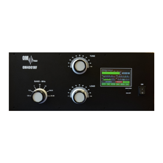
5.1. OM4001HF Front Panel Front panel of the OM4001HF containing the touch TFT display , two control switches and three kmobs for output circuit adjustment. Main Switch. After turning ON, a small 12V power supply for logic, protection circuits and the display will be activated. -
Page 13: Om400Hf Control
Always use the ON/OFF button as this allows for a predetermined (software controlled) time to cool down the tube and inside the PA compartment. 5.2. OM4001HF control Turn ON the green Main Power switch and the home screen will lights up. Initial control touch buttons are visible on the bottom line. -
Page 14: Preparing For Operation
5.3 Preparing for operation In STBY the amplifier is in bypass-mode and your transceiver is directly connected to the antenna. Maximum allowed power in bypass mode is 200 Watts! The bypass RF power is displayed if PA is in standby mode. To turn PA ON press ON/OFF button on the front panel (black one) and hold it abt. - Page 15 Press INFO button Type of supported TCVR and working A new button is visible – SET Umain. Press it. frequency are visible on the display. AUTO LED is ON. Type in the actual setting of the primary Type of supported TCVR and working voltage tap and press ENT.
- Page 16 Press SET for your callsign edit. The keyboard Type of supported TCVR and displays. working frequency are visible on the display. AUTO LED is ON. Type of supported TCVR and working Type your callsign and press ENT. frequency are visible on the display.
- Page 17 Electronic Bias Settings (EBS) is a significant feature of this power amplifier. It automatically allows lower plate current after pressing the PTT, regardless of whether operating CW or SSB mode, when no RF signal is present at the input. At the moment an RF signal is applied, the bias will automatically change to its working value.
- Page 18 By pressing the SERVICE button we are in the SERVICE settings mode. Type of supported TCVR and working Scroll to selected line and press SHOW or frequency are visible on the display. SET (depending on the line). AUTO LED is ON. We selected last 20 FAULTS to show.
- Page 19 Scroll to CALIBRATION Ip, Is and press SET. Type of supported TCVR and working Calibration will be done automatically. frequency are visible on the display. AUTO LED is ON. Scroll to SWR PROTECT and press SET. Type of supported TCVR and working This feature allows user to switch OFF the SWR frequency are visible on the display.
-
Page 20: Operation Mode
AUTO LED is ON. NOTE: The OM4001HF is tested at factory at a maximum output power of 4000W into a 50 Ohm load. A unique Tuning table, with TUNE and LOAD values for every band, is supplied with each PA. - Page 21 When the antenna impedance has greater variance from 50 Ohms, it may be the case that the PA cannot deliver the full power 4000W, or some of the protection circuits may be automatically activated. In such cases we recommend doing a manual tuning. The best indication of proper PA tuning is the Screen Current.
-
Page 22: Maintenance
6.1. Indication of Fault Conditions If a fault condition appears during the operation of the amplifier, the safety circuits of OM4001HF will react immediately. There are several types of warning or fault messages that may appear on the display when any of the protection circuits are activated. - Page 23 AUTO LED is ON. Never try to change or move any part inside the amplifier except the tube or fuses. Substitution of parts may void intrinsic safety! Manufacturer’s contacts: OM POWER, s.r.o. 930 30 Báč 126 SLOVAKIA Email: om-power@om-power.co...
-
Page 24: Fuse Replacement
6.2. Fuse Replacement The user is allowed to change mains fuses (6.3 x 32mm), accessible from the rear panel, only. In the case of fuse (fuses) interruption inside the power amplifier, exchange can be carried out only by professionally qualified persons! Internal fuses are located mainly on the SWITCH-on board (next to the HV transformer). -
Page 25: Appendix
Primary section of the HV transformer is switchable for three values of AC voltage (220, 230, 240V) Factory settings is 230VAC. Before first starting the PA we recommend checking that the correct value is selected according to the AC voltage in your network. Side view on the opened OM4001HF HV supply board AC Selector... -
Page 26: Om4001Hf Firmware Upgrade
OM Power website http://www.om-power.com/downloads. Store it to OM4001HF folder created on your PC. NOTE: Use a serial straight cable and connect the PC port on the OM4001HF rear panel with a COM port on the PC. Open folder OM4001HF on your PC, find the MX460L.exe file and run it. - Page 27 Select the Firmware tab and click on the LOAD BIN button. Choose OM4001HF Vxxx.bin file in the Type of supported TCVR and working OM4001HF folder. frequency are visible on the display. AUTO LED is ON. Switch ON the power amplifier using the front panel green ON switch.
- Page 28 At the end you will return to the main screen of OM4001HF. Switch PA OFF, disconnect the PC serial AUTO LED is ON. cable and you are ready to use the OM4001HF with the new firmware.
-
Page 29: Control Panel Connectors Pin-Out
7.3. Control panel (rear side) connectors pin-out PC connector DB 9 female RS232 connection to the computer. For UPRADE firmware communication connect pin 2 TX-D, pin 3 RX-D and pin 5 GROUND KEY IN – RCA connector Input signal PTT switching voltage / current 5V /2mA) KEY OUT –... -
Page 30: Block Diagram Of The Om4001Hf Power Amplifier
7.4. Block Diagram of the OM4001HF Power Amplifier... -
Page 31: Troubleshooting
7.5. Troubleshooting The OM4001HF power amplifier contains several protection circuits, which constantly monitor operation of the Amplifier. When the firmware defined parameters exceed defined operating levels, a WARNING appears in the LAST EVENTS window of the PA front panel. If some parameters exceed a defined critical level, a FAULT is activated and the PA will automatically switch to STBY mode. - Page 32 Grid voltage is low Check grid power supply Low voltage on the grid. Check fuse F9 on HV supply board. Check fuse F10 on HV supply board and fuse F1 on the Check screen power supply Screen voltage error Screen board.
-
Page 33: Factory Reset
7.6. Factory reset: In the case of very abnormal behavior of the OM4001HF it is possible to do a factory reset. This will reset all the amplifier parameters back to the factory default values. Press and hold the ON/OFF button and press the green Main power switch for several seconds until the following display appears.
Need help?
Do you have a question about the OM4001HF and is the answer not in the manual?
Questions and answers
Slight xformr hum under load
A slight transformer hum under load in the OM POWER OM4001HF could be caused by normal magnetic vibration of the transformer laminations or components under electrical load. This is generally typical and not considered a fault unless it becomes excessive.
This answer is automatically generated