
Related Manuals for OM POWER OM1500


Summary of Contents for OM POWER OM1500
-
Page 1: Power Amplifier
Instruction Manual OM1500 SHORTWAVE PLUS 50 MHz POWER AMPLIFIER OM POWER, s. r. o. 930 30 Báč 126 SLOVAKIA E-mail: om-power@om-power.com... -
Page 2: Table Of Contents
TABLE OF CONTENTS SAFETY INSTRUCTIONS ……………………………………………… GENERAL INFORMATION …………………………………………… 2.1. Introduction ……………………………………………………………….. 2.2. Specification ……………………………………………………………..2.2.1. Parameters …………………………………………………………………. 2.2.2. Protection Circuits ………………………………………………………… 2.2.3. Indicators ………………………………………………………………….. 2.2.4. Features …………………………………………………………………… GENERAL DESCRIPTION ………………………………………………. 3.1. HF part ……………………………………………………………………. 3.2. Power Supply …………………………………………………………….. 3.3. Safety Devices ……………………………………………………………. - Page 3 Indication of Fault Conditions …………………………………………. 6.2. Fuse Replacement . .…………………………………………………..6.3. Tube Replacement …………………………………………………..6.4. Cleaning ……………………………………………………………..APPENDIX ……………………………………………………………... 7.1. Primary AC voltage selection …………………………………………… 7.2. Removing the HV transformer ………………………………………….. 7.3. Block Diagram of the OM1500 Power Amplifier …………………………...
-
Page 4: Safety Instructions
WARNING! DANGEROUS HIGH VOLTAGE! The OM1500 power amplifier is using high voltage up to close 3000V DC, which is very dangerous for human life! Follow strictly all the safety instructions listed below, please! WARNING! NEVER ALLOW CHILDREN to play around PA, to touch power... -
Page 5: General Information
GENERAL INFORMATION 2.1. Introduction The OM Power model OM1500 is a manual tuning power amplifier, designed for use on all short wave amateur bands from 1.8 to 29.7 MHz (incl. WARC bands) + 50 MHz and all modes. It is equipped with one GS23B ceramic tetrode. -
Page 6: Protection Circuits
2.2.2. Protection Circuits There is several special protection circuits used in the amplifier. They are activated when one or more of next parameters exceed defined values or some unwanted occasion occurs. · VSWR too high · Anode current too high ·... -
Page 7: General Description
The output of the amplifier is a Pi-L circuit. The ceramic capacitor for TUNE and LOAD are divided. This enables the amplifier to be tuned exactly and makes it possible to easily return to the previously set positions after band changes. Top view on the opened OM1500 Power Supply board Tetrode GS23B... -
Page 8: Power Supply
3.2. Power Supply Power amplifier is using a 2.3 kVA toroidal transformer. A soft start is provided using relays and resistors (on the front board). The high anode voltage is made by combining 1x600 V and 3x800V sections (total 3000V) @ 1A. -
Page 9: Grounding
CINCH-socket is used. On the side of your transceiver you have to use a socket suitable for this transceiver. During transmitting the middle pin is connected to the ground. The relays of the OM1500 have to be switched earlier than HF is... -
Page 10: Main Supply
applied (cold switching). Modern transceivers they have a time delay between PTT switching and power output. CAUTION If you are using an older transceiver or transmitters without time delay, we recommend to connect the PA in such a way that the transmit/receive switch (foot switch for example) is connected with the KEY IN socket of the amplifier. -
Page 11: Operation
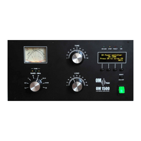
OPERATION WARNING! Before switching PA on, make sure that amplifier is grounded, antenna or dummy load is connected, and line cord is putted to the outlet. Be sure you selected AC input by 7.1. CAUTION Before switching PA on, check all connections between PA and TCVR. CAUTION Do not turn PA on for at least 2 hours after unpacking it and locating in its operating location. - Page 12 LOAD Output capacitor tunes antenna load resistance to the amplifier. Capacity is low at „100“ and high at "0" on the scale. TUNE LED Three LEDs assists in tuning the amplifier WATMETER - Analog double system meter for forward and reflected power measuring ON / OFF - Long press (abt.
-
Page 13: Preparation For Operation
ON AIR - Transmitting mode LED STBY - Standby mode LED FAULT - Failure LED - PA is „ON“ LED - OPER / STBY - Press to switch between Standby and Operation mode - Return to the previous level MENU - Enter the Menu DOWN - Scroll down... - Page 14 In the STBY mode Antenna output can be changed (ANT1, ANT2, ANT3) by pressing S4. Display information can be changed, too. Press S3 to do it. There are 3 different display settings possible in the OM1500. To set display parameters, go to the next part of this manual for more details.
-
Page 15: Display Menu
5.2.1. Display menu The OLED display shows couple of parameters or texts. Display has 4 lines. Three of them are editable. In every line user can select different parameters, using MENU. See next pictures. After pressing MENU (S2) S1–S4 buttons changed their functions. To edit display parameters, press DISP button. -
Page 16: Settings Menu
S2 and S3 now changed their functions. To edit left side of the second line, press LEFT button Go UP or DOWN to select desired parameter. Press ENT confirm selection. If you finish left side settings, press ESC to go back to the side selection. To start edit right side, press RIGHT button….etc. - Page 17 Electronic Bias Settings (EBS) is one of significant feature of the power amplifier. It allows to set low plate current after pressing the PTT regardless of whether you have CW or SSB mode, until RF signal is no present at the input. At the moment when RF signal comes to the input of PA, bias will automatically change to its working value.
-
Page 18: Service Menu
If you wish to restore factory default parameters, use UP or DOWN button to select Restore default parameters. Then press ENT. Press YES to confirm restoring. Use UP or DOWN button to select LCD contrast. Press ENT. Use UP or DOWN button to set contrast value. - Page 19 Use Service menu after replacing the tube. This is step No. 1. To enter Service menu, go to the MENU first, then press SERV button. Use UP or DOWN button to check software version. Use UP or DOWN button to select Time ON parameter.
- Page 20 Use UP or DOWN button to select Warnings. Press ENT to see warning numbers or letters (see the table in chapter 6). Press ESC to go back to the Service menu. Use this procedure after replacing the tube. This is step No. 2. Scroll UP or DOWN to select EBS1 settings.
-
Page 21: Operation Mode
Use UP or DOWN to select Calibration Ip & Is. Press ENT to do it. Ip and Is calibration runs in the background. Result only is visible on the display. Press ESC to go one level back. Use UP or DOWN to select Min. turns of blower. - Page 22 Changing of DSP allows user to watch couple of basic parameters of the PA in operation mode without input RF signal. Notice: These are three default display settings (software version 4.2.) Check all connections again. Set BAND selector, TUNE and LOAD capacitors according to TCVR parameters and delivered tuning table (see next part for more details).
-
Page 23: Tuning Of The Power Amplifier
(TUNE and LOAD) 5.4. Tuning of the Power Amplifier The OM1500 power amplifier is operated in class AB. Thus it’s possible to obtain a maximum output power at excellent linearity. For this purpose the amplifier has to be tuned carefully. - Page 24 CAUTION The operation of a mistuned PA will cause malfunctions, the increase of grid current and problems with TVI/BCI. CAUTION If the input power is higher than 10W and the power amplifier is NOT correctly tuned, the safety devices will switch it to STBY. After switching the amplifier to STBY, you need to switch it back to the OPER mode by pressing RESET button shortly.
- Page 25 Press OPER to enter operation mode. Apply low input power and press PTT. Be sure you selected right BAND, TUNE and LOAD knob positions. If you made some mistake, fault message appears: Safety circuit stopped transmitting, fault LED is ON (Fault code 4 is saving to the memory).
- Page 26 Remember Always use TUNE knob to get maximum output power. Use LOAD knob to get TUNE indicator on the display to the middle position between both arrows. Simultaneously check if Is graph indicator stays within the boundaries. Repeat both steps more times. Try to watch DSP2 and DSP3 at the maximum output power also.
- Page 27 Press S2 (TUNE) button in OPER mode to start the second method of fine tuning. PA is in the operation mode. After TUNE button (S2) was pressed, it changes its function. Now STOP is blinking. Do not press STOP button yet! By pressing PTT the input attenuator is automatically included first.
- Page 28 If only green LED lights, right LOAD knob position was found successfully. Release the PTT and press S2 (STOP) to stop fine tuning finally. View on the properly tuned PA. Analog meter shows forwarded and reflected power, green confirms right tuning. After this procedure the amplifier is tuned correctly and ready to give 1500W output power in all operation modes.
-
Page 29: Maintenance
If a fault condition appears during the operation of the amplifier, the safety circuits of OM1500 will react. There are several warning or fault messages possible to appear on the display, when some of the protection will be activated. The OM1500 power amplifier can... - Page 30 Next table shows limited values for the safety circuits activation. Fault code Parameter Warning level Fault level Power Output is too high 1700W 1800W Reflected power is too high 250W 300W Power Input is too high 100W Low output power (tune) >...
- Page 31 An example shows situation when Input power is too high. By pressing PTT safety circuit will react quickly, error message appears and FAULT LED starts blinking. In this case screen current exceeds limited value (60mA). After abt. 1 sec. PA returns to TX mode. Reduce Input power to avoid fault repeating.
-
Page 32: Fuse Replacement
In the case of fuse (fuses) interruption inside the power amplifier, contact your dealer, please. Internal fuses are located mainly on the SWITCH-on board (next to the HV transformer). One special fuse is used in the model OM1500. In the case of an accidental discharges in the tube this fuse saves HV supply circuits. -
Page 33: Tube Replacement
Fuse is installed behind TUNE capacitor, close to the blower. Fuse F3 6.3. Tube Replacement In the case of vacuum tube damaging, contact the manufacturer or your dealer for ordering new one. You will get instructuions how to change it. Be very careful, you will do it only on your own risk! After tube replacing automatic BIAS adjustment must be done. -
Page 34: Appendix
240V). Factory settings is 230VAC. Before first starting of the PA we recommend to check the correct value according to the AC voltage in your network. Change the settings, if necessary. Side view on the opened OM1500 HV Transformer AC selector Remove the upper lid first. -
Page 35: Removing The Hv Transformer
NOTE AC selector range can be changed in the production according to the specific conditions in individual countries. If necessary, manufacturer can prepare selector for other AC range. Here, for example, AC selector was made for the range of 210 – 230 VAC. 7.2. - Page 36 Weight of the PA was distributed (transformer has 12 kg, rest of the PA cca 10 kg). When refitting the transformer, watch to the correct location of individual sections and wires. An older version of transformer termination shows the next picture. Transformer secondary wiring connector Connect to the rear board –...
- Page 37 Latest the manufacturer changed the type connectors transformer termination. New WAGO connectors they have different colour for every contact. This corresponds approx. to the shrink foil colour transformer terminals (white, yellow, orrange, blue - primary wiring - J3 connector).
-
Page 38: Block Diagram Of The Om1500 Power Amplifier
7.3. Block Diagram of OM1500 Power Amplifier...
Need help?
Do you have a question about the OM1500 and is the answer not in the manual?
Questions and answers