
Subscribe to Our Youtube Channel
Related Manuals for OM POWER X8NOM4000A


Summary of Contents for OM POWER X8NOM4000A
- Page 1 Instruction Manual OM4000A SHORTWAVE POWER AMPLIFIER FCC ID: X8NOM4000A WWW.OM-POWER.COM OM POWER, s.r.o. 93030 Báč 126, SLOVAKIA Contact : +421 905 321 410 e-mail : om-power@om-power.com Page 1 from 38...
-
Page 2: Table Of Contents
TABLE OF CONTENTS GENERAL INFORMATION 1.1. Introduction 1.2. Specification 1.3. Parameters 1.4. Protection Circuits 1.5. Indicators SAFETY INSTRUCTIONS GENERAL DESCRIPTION 3.1. HF Part 3.2. Power Supply 3.3. Safety Devices INSTALLATION 4.1. Grounding 4.2. Coaxial Cable 4.3. I/O Box and Interface 4.4. - Page 3 Example of connection USB Micro KEYER II with YAESU or ELECRAFT 7.8. Example of connection PA with MicroHAM MKII, (MK2R+ etc.) CI-V output 7.9. Controlling the OM Power automatic amplifiers with Flex Radios Series 6xxx 7.10. Block diagram of the OM4000A Page 3 from 38...
-
Page 4: General Information
1.1. Introduction he OM Power model OM4000A is a fully automatic power amplifier, designed for use on all short wave amateur bands from 1.8 to 29.7 MHz (including WARC bands) and all modes. It is equipped with a two pieces of ceramic tetrode FU728F. -
Page 5: Protection Circuits
1.2.2. Protection Circuits There are 11 special protection circuits used in the amplifier. They are activated when one or more of next parameters exceed defined values or some unwanted occasion occurs. VSWR too high • Input power too high • Output power too high •... -
Page 6: Safety Instructions
SAFETY INSTRUCTIONS WARNING! DANGEROUS HIGH VOLTAGE INSIDE! The power amplifier is using high voltage up to 3400V DC, which is very dangerous for human life! Read next safety instructions carefully first, before you will start to install and operate power amplifier! NEVER VIOLATE NEXT RULES! WARNING! NEVER ALLOW CHILDREN to play around PA or to touch power amplifier or connected... -
Page 7: General Description
CAUTION The amplifier must be installed in such a way that free flow of hot air from the tube is allowed. The amplifier must not be installed in a constrained surrounding (i.e. tight shelves etc.). During long time operation ventilation grid can reach high temperature. Do not touch the top cover of the PA in these places during operation. -
Page 8: Power Supply
The output of the amplifier is a Pi-L circuit. The ceramic capacitor for TUNE and LOAD are divided. This enables the amplifier to be tuned exactly and makes it possible to easily return to the previously set positions after band changes. Top view on the opened OM4000A Tetrode FU728F PWR Meter... -
Page 9: Safety Devices
3.3. Safety Devices Control and monitoring circuits ensure control and safety during malfunctions of the PA. These are on the Control board, which is located on the chassis subpanel. INSTALLATION NOTE Read this chapter carefully prior you will start installation. Before unpacking inspect shipping woody container first, if it is not damaged. -
Page 10: I/O Box And Interface
Rear view of the amplifier OM4000A AC Sockets Fuses OUTPUT REMOTE I / O Interface INPUT 4.3. I/O Box and Interface Control of Amplifier and communication with TCVR as well as Antennas / BPF switching can be done via the rear panel I/O Interface. Control cable maintains TX / RX switching of the PA (TX GND). - Page 11 KEY IN RCA Phono - Input signal PTT switching voltage / current 5V /2 mA) KEY OUT RCA Phono - Output signal PTT (maximum switching of 30V / 50mA) CI-V Mono 3.5mm Jack for connection of ICOM TCVRs or devices that provide compatible CI-V protocol.
- Page 12 CAUTION! We only recommend using ALC feature while operating RTTY, FM and other 100% duty modes. CONTROL The CONTROL socket is a single DB-15 connector that provides many connections to the amplifier from your transceiver. Use shielded cable all connections to this connector. You will need to fabricate a cable with the proper connector for your transceiver or use individual connectors as described below.
-
Page 13: Mains Supply
21. BPF 12m 22. BPF 10m 23. COMMON BPF port 24. NC 25. GND 4.4. Mains Supply CAUTION Be sure you got PA with properly terminated line cable, corresponding with your power system’s outlet. If not, contact your dealer. In such a case you should make the necessary changes using a licensed electrician. -
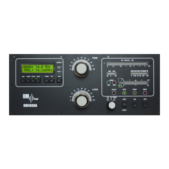
Page 14: Operation Elements
CAUTION Before switching PA on, check all connections between PA and TCVR. CAUTION Do not turn PA on for at least 2 hours after unpacking it and locating in its operating location. Especially when amplifier is moved from a cold place to a warm one because not visible condensation may develop, and this could result in damage to the high voltage circuits of the PA. - Page 15 TUNE Anode capacitor for tuning, tuning of higher frequencies to "0", lower frequencies to “100”. LOAD Output capacitor tunes antenna load resistance to amplifier. Capacity is low at „100“ and high at "0" on the scale. You switch off the amplifier by pressing this button. You switch on the amplifier by pressing this button.
-
Page 16: Configuration Of Power Amplifier
INHIBIT Indicates interruption of transmission during the tuning process of the PA. If indicated by RED LED then PA is in STBY mode. If during a retune operations within the same BAND, then the PA will retune according to the frequency of the transceiver. When changing the BAND – INHIBIT will stay lit until the KEY IN is released and the tuning process will start. -
Page 17: Tcvr Support Settings
Example of Automatic mode with ICOM TCVR. Type of supported TCVR and working frequency is visible on the display. AUTO LED is ON 5.2.1. TCVR Support Settings Supported transceivers : ICOM, ELECRAFT, KENWOOD, TEN-TEC, ORION, YAESU. Press SET button and scroll UP/DWN to CHOOSE TCVR Confirm CHOOSE TCVR by pressing SET again and scroll UP / DWN to your... -
Page 18: Connection With Not Supported Tcvrs
By scrolling UP / DWN select desired Baud Rate which must be the same as baud rate used by your transceiver (please refer to your transceiver user manual). To confirm your selection press SET. When using Yaesu TCVR you need to configure the STOP BIT parameter correctly and confirm selection with SET. -
Page 19: Communication Loss
5.2.3. Communication loss If TCVR is not connected or communication settings are incorrect, the message “COMMUNICATION LOST” will be displayed. You can still use PA by entering MANUAL mode (MAN Button) or by correcting the transceiver connection problem. Example of Communication loss message. 5.2.4. -
Page 20: Bandpass Filter Settings
Then select how many antennas you want per current band (1 or 2) and always confirm your selection by pressing SET. By scrolling UP / DWN you assign which PORT is used on your external antennas switch for this particular antenna. (ANT 1 ON PORT 01). -
Page 21: Mute Option
Then select if you want to erase all settings (pressing TUNE) or just one setting value (SET button). In the case of resetting a single parameter use UP / DWN to select which option and confirm by SET. 5.2.7. MUTE option When operating the OM4000A with an Icom transceiver without TX INHIBIT for disabling TX, we recommend to block transmitting during tuning of the PA (mainly while operating FM /RTTY/ AM) using ALC connection. -
Page 22: Operation In Manual Mode
Using SET and scrolling UP / DWN select SET LCD CONTRAST and confirm it by SET. By pressing Up or DWN you can vary contrast of the LCD display. Finally press SET to confirm selected value. 5.2.9. Operation in MANUAL mode To enter Manual mode of the PA press MAN. - Page 23 WARNING! Before starting tuning you have to check if the right antenna or a 50 Ohms load resistance is connected at the antenna output! CAUTION The operation of a mistuned PA will cause malfunctions, the increase of grid current (the GRID-MAX-LED will light up) and problems with TVI/BCI.
- Page 24 The amplifier is prepared for operation with the following automatic steps: Toroidal transformers are switched on step by step. • The cooling blower for the final tube is switched on. • The multi-meter bar graph measures the high voltage; the normal value is 3.3 KV •...
- Page 25 13. Set TUNE knob to maximum output power (RF POWER LED lights up max. right). After this procedure the amplifier is tuned correctly and ready to give 1500W output power in all operation modes with no time limited operation possibility. At optimal tuning and full output power a positive max.
-
Page 26: Maintenance
MAINTENANCE 6.1. Indication of fault conditions OM4000A has the following indication LED on the front panel: GRID MIN - indication of first gird current GRID MAX - max. First grid current exceeded - measuring of anode voltage by bar graph - measuring of anode currency by bar graph FAULT - fault... -
Page 27: Fuse Replacement
In case your OM4000A amplifier is not working correctly, please contact the manufacturer or your dealer. Manufacturer contacts: OM POWER, s.r.o. 930 30 Bac 126 SLOVAKIA Email: om-power@om-power.com Dealer in USA: Array Solutions 2611 North Belt Line Road Suite # 109... -
Page 28: Example Of Connection With Icom
7.1. Page 28 from 38... -
Page 29: Example Of Connection With Elecraft
7.2. Example of connection for ELECRAFT Page 29 from 38... -
Page 30: Example Of Connection With Yeasu
7.3. Example of connection with Yeasu Page 30 from 38... -
Page 31: Example Of Connection With Antenna Switch And Bpf
7.4. Example of connection with antenna switch and BPF Page 31 from 38... -
Page 32: With Ic7800 Or Ic7700
7.5. Example of connection USB micro KEYER II with IC7800 or IC7700 Page 32 from 38... -
Page 33: With Another Icom
7.6. Example of connection USB micro KEYER II with another Icom Page 33 from 38... -
Page 34: With Yaesu Or Elecraft
7.7. Example for connection USB micro KEYER II with Yeasu or ELECRAFT Page 34 from 38... -
Page 35: Example Of Connection Pa With Microham Mkii, (Mk2R+ Etc.)
7.8. Example of connection PA with MicroHAM MKII, (MK2R+ etc ) with CI-V output Page 35 from 38... -
Page 36: Controlling The Om Power Automatic Amplifiers With Flex
7.9. Controlling the OM Power automatic amplifiers with Flex Radios Series 6xxx Download and install the software for rerouting the serial ports , for example DDUtil http://k5fr.com/DDUtilV3wiki/index.php?title=Download In Setup / Features set conenction for Flex radio {for example on COM4}... - Page 37 In Setup / Ports set rerouting ports / for example OM4000A is connected to COM2 trough USB/RS232 adapter. Amplifier connect to redirected port ( COM2 ) and on OM4000A into set up menu choose TCVR Kenwood and 9600baud rate . NOTE This was just one of more connection possibilities with FLEX RADIO SERIES 6XXX...
-
Page 38: Block Diagram Of The Om4000A
7.10. Block Diagram of the OM4000A Power Amplifier Page 38 from 38...
Need help?
Do you have a question about the X8NOM4000A and is the answer not in the manual?
Questions and answers