
Related Manuals for OM POWER OM4001A


Summary of Contents for OM POWER OM4001A
- Page 1 MADE IN SLOVAKIA OM4001A SHORTWAVE POWER AMPLIFIER WWW.OM-POWER.COM OM Power, s.r.o. 93030 Báč 126, SLOVAKIA Contact : +421 905 321 410 e-mail : om-power@om-power.com e-mail : om-power@om- power.com...
-
Page 2: Table Of Contents
………………………………………………………. 1.2. Specification ………………………………………………………. 1.2.1. Parameters ………………………………………………. 1.2.2. Protection Circuits ………………………………………………. 1.2.3. Features ………………………………………………………. 1.2.4. The Advantages of OM4001A …………………………………… 2. SAFETY INSTRUCTIONS ………………………………………………. 3. GENERAL DESCRIPTION ………………………………………………. 3.1. HF Compartment …………………………………………………………. 3.2. Power Supply …………………………………………………………. 3.3. Safety Devices …………………………………………………………. - Page 3 7.4.3. Remote Control without own IP Address, behind a router ..7.5. OM4001A firmware upgrade …………………………..………… 7.6. Icom connection with OM4001A ……………………………….… 7.7. Yaesu plus BPF plus ANT Switch connection with OM4001A … 7.8. Control panel connectors pin-out …………………………….…… 7.9. Block Diagram of the OM4001A Power Amplifier …………..… 7.10.
-
Page 4: General Information
GENERAL INFORMATION 1.1. Introduction he OM Power model OM4001A is designed for all short wave amateur bands from 1.8 to 29.7 MHz (including WARC bands) and all modes. It is equipped with a two ceramic tetrodes FU-728F. 1.2. Specification 1.2.1. Parameters Frequency Coverage Amateur Bands 1.8 –... -
Page 5: Protection Circuits
1.2.2. Protection Circuits There are several protection circuits used in the amplifier. They are activated when one or more parameters exceed defined values or some unwanted condition occurs. VSWR too high • Anode current too high • Anode voltage error •... -
Page 6: Safety Instructions
Never turn the amplifier on without the upper lid in place. DO NOT ATTEMPT TO SHORT OR BYPASS safety switch under upper lid! The OM4001A amplifier should not be used in a WET or HUMID environment or be exposed to RAINFALL! -
Page 7: General Description
FU-728F in a grounded-cathode circuit (input into control grids). The OM4001A amplifier achieves excellent linearity by the voltage stabilization of the control grid bias and the screen voltage. The power input is fed to the control grids, using a broadband input circuit with an input impedance of 50 Ohms. - Page 8 The output of the amplifier is a Pi-L circuit. The variable capacitors for TUNE and LOAD are seperate. This enables the amplifier to be tuned exactly and makes it possible to easily return to the previously set positions after band changes. Top view on the opened OM4001A Tetrode FU728F Blower...
-
Page 9: Power Supply
3.2. Power Supply This Power amplifier uses two 3 KVA toroidal transformer. A soft start is provided using relays and resistors (placed on the switch-ON board). The high voltage is made by combining 8 x 420 V (total 3360V) @ 2.5A . Each has its own rectifier and filter. In the high voltage circuit, safety resistors are employed to protect the amplifier against overload (placed on the power supply board). -
Page 10: Grounding
50 Ohm cable. For the connection between the power amplifier and the antenna, RG213 or similar coaxial cable suited for high power is recommended. SO-239 sockets with Teflon insulation are used for the HF INPUT and OUTPUT connectors. Rier view of the amplifier OM4001A Mains Plugs Fuses... -
Page 11: Control Cable
During transmitting the middle pin is connected to the ground. The relays of the OM4001A have to be switched earlier than HF is applied (cold switching). Modern transceivers they have a time delay between PTT switching and power output. -
Page 12: Operation
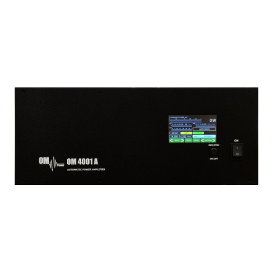
5.1. OM4001A Front Panel Front panel of the OM4001A is almost empty…Containing only the touch TFT display plus two control switches. Main Switch. After turning ON, a small 12V APU for logic, protection circuits and the... -
Page 13: Om4001A Control
PA OFF. Always use the ON/OFF button as this allows for a predetermined (software controlled) time to cool down the tube and inside the PA compartment. 5.2. OM4001A control Turn ON the green Main Power switch and the home screen will lights up. Initial control touch buttons are visible on the bottom line. - Page 14 information screen also Type of supported TCVR and provides an overview of the last working 20 warnings and faults: frequency are visible on the display. Press FAULTS. AUTO LED is ON. Type of supported TCVR and working frequency are visible on the Press EXIT to go back to the home display.
- Page 15 OM4001A has permanent information about the transmit frequency and is immediately ready for transmitting. With a setting of NO CAT the OM4001A detects transmit frequency from the input signal. With the input signal frequency changing the PA automatically reacts and tunes itself to optimal output parameters..
- Page 16 You selected IC7800 addr.6AH and 19200 Bd. Press SET to write to the memory, then press EXIT to Type of supported TCVR and back SETTINGS working possibilities. frequency are visible on the “SET OTHER ADDRESS” means display. that you must add here a new type of ICOM TCVR which is not defined in the table (its address AUTO LED is ON.
- Page 17 Next SETTINGS position Type of supported TCVR and display parameters. First choose the working background color. Scroll on it and choose the color (left/right). frequency are visible on the display. Press SAVE twice, then scroll to OWN CALL. AUTO LED is ON. Type of supported TCVR and Press SET for your callsign edit.
- Page 18 Type of supported TCVR and Press NETWORK SETTING and working then press ENTER. frequency are visible on the display. AUTO LED is ON. Here the user has the option to set Address, Network mask, Type of supported TCVR and Default gateway, Port number. working frequency are visible on the display.
- Page 19 Electronic Bias Settings (EBS) is a significant feature of this power amplifier. It automatically allows lower plate current after pressing the PTT, regardless of whether operating CW or SSB mode, when no RF signal is present at the input. At the moment an RF signal is applied, the bias will automatically change to its working value.
-
Page 20: Preparing For Operation
PA will start tube heating. It will take 180 seconds. Turning PA ON is possible ONLY from the home screen! If you have other display active, press EXIT more times to go back to the home screen. (These same functions are also available on the OM Power Remote Control PC Application) - Page 21 The “Tube Heating Timer” is visible on the display. Wait until Type of supported TCVR and the required 180 seconds is working complete before placing frequency are visible on the display. amplifier in OPERATE Mode. AUTO LED is ON. After heating is completed, the Type of supported TCVR and working PA will light the STBY mode indicator and this Main display...
- Page 22 The Menu display allows the user to Type of supported TCVR and working go deeper into the SETTINGS mode, MEASuring mode or SERVICE mode. frequency are visible on the display. AUTO LED is ON. Type of supported TCVR and working Press SETTING button.
- Page 23 Type in the actual setting of the primary Type of supported TCVR and working voltage tap and press ENT. frequency are visible on the display. Press EXIT twice to go back to the Menu display. AUTO LED is ON. This is the actual physical setting of the primary voltage tap. It is just information for the processor, which protects the permitted limits ( up or down) for a given value of the primary voltage (protection circuit).
- Page 24 Type of supported TCVR and working Press EXIT to go back to the Menu display, then press SERVICE. frequency are visible on the display. AUTO LED is ON. Now we are in the SERVICE settings mode. Type of supported TCVR and working Scroll to selected line and press frequency are visible on the display.
- Page 25 You can try to do this manually, too. Type of supported TCVR and working Scroll to SET EBS1 MANUAL and frequency are visible on the display. press SET. Use up/down buttons to set 20mA or as close as possible value and press AUTO LED is ON.
-
Page 26: Operation Mode
5.4. Operation mode Before switching to operation mode, check all connections between PA and TCVR. We are now back in the Main display, graphs defined, Type of supported TCVR and working antennas preprogrammed, CAT was set. We are ready to go to the frequency are visible on the display. - Page 27 M-TUNE means entry into the manual tuning mode. It allows fine tuning of the PA, especially in cases where the antenna impedance is different from real 50 Ohms. For proper adjustment we need to show Screen current (at least). By Pressing M-TUNE. A new screen is visible and TUNE and LOAD adjustment sliders appear.
- Page 28 AUTO LED is ON. These parameters were SAVED. NOTE: The OM4001A is factory adjusted to a maximum output power of 4000W into a 50 Ohm load. A unique Tuning table, with TUNE and LOAD values for every band, is supplied with each PA.
- Page 29 Press PTT, check the Ig2 (I Screen on the display). If it is ok (bellow +40mA ), • gradually increase the input power until the PA reaches about 70% of its maximum output power. Using the TUNE buttons, adjust for maximum FORWARD POWER while monitoring the •...
-
Page 30: Maintenance
6.1. Indication of Fault Conditions If a fault condition appears during the operation of the amplifier, the safety circuits of OM4001A will react immediately. There are several types of warning or fault messages that may appear on the display when any of the protection circuits are activated. -
Page 31: Fuse Replacement
Never try to change or move any part inside the amplifier except the tube or fuses. Substitution of parts may void intrinsic safety! Manufacturer’s contacts: OM POWER, s.r.o. 930 30 Báč 126 SLOVAKIA Email: om-power@om-power.co 6.2. -
Page 32: Tube Replacement
One special fuse, filled with sand, is used in the model OM40001A. In the case of an accidental discharges or short within the tube this fuse (4 Amps fast, filled with sand) saves the HV supply circuits. Type of supported TCVR and working frequency are visible on the display. - Page 33 Side view on the opened OM4001A HV supply board AC Selector SW ON board HV Transformers Remove the upper lid first. On the right side of the PA, there are two PCBs mounted. On the right upper side is Switch ON board where AC selector is located.
-
Page 34: Controlling Om4001A With Flex Radio Series 6Xxx
Connect the chosen COM port and the transceiver port ( TCVR DB9 )to the OM Power amplifier with a null modem serial cable (both ends of the cable have a female DB-9 connector and pins 2 and 3 are crossed). - Page 35 Amplifier CAT setting. AUTO LED is ON. Flex Radio 6xxx series connection using USB output Connect from the Flex USB port directly to the TCVR port on the OM4001A using an USB – port adapter and FTDI serial a null modem serial cable (both ends of the cable have a female DB-9 connectors (pins 2 and 3 are crossed).
-
Page 36: Om4001A Remote Control
Set all parameters in the configuration window according to the picture below. Check that ENABLED is selected in both associated USB windows. Close both windows. The OM4001A will now follow the Band and Frequency changes on the Flex 6XXX. 7.3. - Page 37 Connection setting: Set up TCP/IP address and port: Connect / disconnect to OM4001A:...
- Page 38 View last 20 PA faults: Anennas Settings: Screen selections: Minimal view: NOTE: To return to the normal view from the minimal view just right click with your mouse...
- Page 39 Normal view: Advanced view: Fine tune screen: It is possible to retune the PA TUNE and LOAD remotely (See page 31).
-
Page 40: Remote Control Using Own Public Ip Address
Remote Control using own public IP address: 7.4.1 Changing OM4001A connection settings Connect the LAN connector on the OM4001A to your local Internet with ethernet cable. Open up a WEB browser and enter the Type of supported TCVR and working OM4001A current IP address (default is 192.168.1.222). -
Page 41: Setting Up In The Remote Software
If necessary it is also possible to change the OM4001A local Port number. Make any changes as required in the Connection menu. When finished, click OK. When completely finished, click Apply Settings in the main Menu. 7.4.2 Setting up in the Remote software... -
Page 42: Remote Control Without Own Ip Address, Behind A Router
7.4.3 Remote Control without own IP Address, behind a router If you need to change the OM4001A connection settings for some reason, use point 7.5.1 above. Change router´s settings Open up a WEB browser and enter the routers´s internal IP Address ( usually 192.168.1.1) -
Page 43: Om4001A Firmware Upgrade
Download the firmware upgrade software and latest firmware file for the OM4001A from the official OM Power website http://www.om-power.com/downloads. Store it to OM4001A folder created on your PC. NOTE: Use a serial null modem cable and connect the TCVR port on the OM4001A rear panel with a COM port on the PC. - Page 44 Open folder OM4001A on your PC, find the MX460L.exe file and run it. Type of supported TCVR and working frequency are visible on the display. AUTO LED is ON. Select SETTINGS and choose the COM port you want to use. Baud rate should be 115200.
- Page 45 Switch ON the power amplifier using the front panel green ON switch. Type of supported TCVR and Press SETTINGS to enter the working SETTINGS Menu. frequency are visible on the display. AUTO LED is ON. Choose INFO and press SHOW. Type of supported TCVR and working frequency are visible on the...
- Page 46 NOTE: Do not take any action until this screen disappears! AUTO LED is ON. At the end you will return to the main screen of OM4001A. Switch PA OFF, disconnect the TCVR serial cable and you are ready to use the OM4001A with the new firmware.
-
Page 47: Icom Connection With Om4001A
7.6. ICOM connection with OM4001A... -
Page 48: Yaesu Plus Bpf Plus Ant Switch Connection With Om4001A
7.7. Yaesu plus BPF plus ANT Switch connection with OM4001A... -
Page 49: Control Panel Connectors Pin-Out
7.8. Control panel (rear side) connectors pin-out TCVR connector DB 9 male RS232 connection with TCVR. For CAT communication connect pin 2 RX-D, pin 3 TX-D and pin 5 GROUND CI-V connector Use CI-V connection for communication with ICOM type transceiver. - Page 50 PC connector DB 9 female RS232 connection to the computer. For CAT communication connect pin 2 TX-D, pin 3 RX-D and pin 5 GROUND KEY IN – RCA connector Input signal PTT switching voltage / current 5V /2mA) KEY OUT – RCA connector Output signal PTT (maximum switching of 30V / 50mA) LAN connector Use for connection to the LAN or WAN network.
- Page 51 CONTROL connector D-sub 15 female - GROUND - KEY OUT - ouput signal PTT ( maximum switching of 30V / 50mA - KEY IN input signal PTT – switching voltage / current 5V / 2mA - CI-V CI-V input for Icom CAT. The same as CI-V jack connector - BAND data A input - input BCD Yaesu compatibile code from TCVR - bit 0 - BAND data B input - input BCD Yaesu compatibile code from TCVR - bit 1 - BAND data C input - input BCD Yaesu compatibile code from TCVR - bit 2...
- Page 52 9 - BAND data A - output BCD Yaesu BAND data compatibile code.Use for automatic bandpass filter OM6BPF 10 - BAND data B - output BCD Yaesu BAND data compatibile code.Use for automatic bandpass filter OM6BPF 11 - BAND data C - output BCD Yaesu BAND data compatibile code.Use for automatic bandpass filter OM6BP 12 - BAND data D - output BCD Yaesu BAND data compatibile code.Use for automatic bandpass filter OM6BPF...
-
Page 53: Block Diagram Of The Om4001A Power Amplifier
7.9. Block Diagram of the OM40001 Power Amplifier... -
Page 54: Troubleshooting
7.11 Troubleshooting The OM4001A power amplifier contains several protection circuits, which constantly monitor operation of the Amplifier. When the firmware defined parameters exceed defined operating levels, a WARNING appears in the LAST EVENTS window of the PA front panel. If some parameters exceed a defined critical level, a FAULT is activated and the PA will automatically switch to STBY mode. - Page 55 check plate fuse (page 34). High voltage supply fault. Check the fuses on HV Plate voltage error Check plate power supply board. Low voltage on the grid. Check fuse F4 on SW ON Grid voltage is low Check grid power supply board.
- Page 56 Factory reset: In the case of very abnormal behavior of the OM4001A it is possible to do a factory reset. This will reset all the amplifier parameters back to the factory default values. Press and hold the ON/OFF button and press the green Main power switch for several seconds until the following display appears.
Need help?
Do you have a question about the OM4001A and is the answer not in the manual?
Questions and answers