
Related Manuals for OM POWER OM1002


Summary of Contents for OM POWER OM1002
- Page 1 Instruction Manual OM1002 Solid State 145 MHz Power Amplifier OM POWER, s. r. o. 930 30 Báč 126 SLOVAKIA E-mail: om-power@om-power.com...
-
Page 2: Table Of Contents
TABLE OF CONTENTS GENERAL INFORMATION 1.1. Introduction ……………………………………………………………….. 1.2. Specification ……………………………………………………………..1.2.1. Parameters …………………………………………………………………. 1.2.2. Protection Circuits ………………………………………………………… 1.2.3. Indicators ………………………………………………………………….. SAFETY INSTRUCTIONS ……………………………………………… GENERAL DESCRIPTION ………………………………………………. 3.1. HF part ……………………………………………………………………. 3.2. Power Supply …………………………………………………………….. 3.3. Safety Devices ……………………………………………………………. INSTALLATION ………………………………………………………… 4.1. - Page 3 5.2.2.5. Bias SSB No.1 ………………………………………………………….. 18 5.2.2.6. Bias CW No.1 ………………………………………………………….. 5.2.2.7. Software version ……………………………………………………….. 5.2.3. Operating mode ………………………………………………………… MAINTENANCE ………………………………………………………. 6.1. Indication of Fault Conditions …………………………………………. 6.2. Fuse Replacement . .…………………………………………………..6.3. Cleaning ……………………………………………………………..APPENDIX ……………………………………………………………... 7.1. Block Diagram ………………………………..………........
-
Page 4: General Information
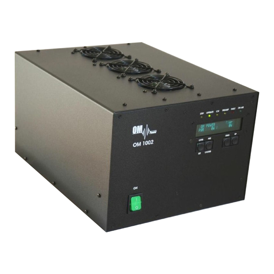
GENERAL INFORMATION 1.1. Introduction The OM Power model OM1002 is a single band, solid state amplifier, designed for duty operation on 2 meter’s amateur band with all modes and no time limit. It is equipped with a new Freescale high rugged N-channel double MOSFET. This amplifier is characterized by compact design, small size and a low weight. -
Page 5: Indicators
WARNING! Never turn the amplifier on without the upper lid in place. WARNING! The OM1002 amplifier is neither to be used in a WET or HUMID environment nor to be exposed to RAINFALL! -
Page 6: General Description
GENERAL DESCRIPTION 3.1. HF part OM1002 power amplifier was designed to achieve the RF performance of the MOSFET, when applied to the 144 – 148 MHz frequency band. Design was tuned for performance at 1000W CW output, 50VDC. It consists of „no tune“ distributed element matching circuits designed to be as small as possible. - Page 7 The coaxial transformer turns ratio was chosen to meet required impedance level and the length of the coax was tuned to achieve maximum efficiency and maximum power transfer between the device and its load impedance. Top view on the opened OM1002 HF Board Output LPF...
-
Page 8: Power Supply
3.2. Power Supply The amplifier uses two power supplies. A professional switch mode power supply 50V / 32A for power amplifier, and small 12V power supply for logic and protection circuits. Main power supply contains special soft start circuits, uses two fans, which are visible from the rear side of PA. -
Page 9: Installation
INSTALLATION NOTE Read this chapter carefully prior starting with installation. Before unpacking inspect shipping carton first, if it is not damaged. Keep all of packing parts for possible future shipment. Check unpacked power amplifier. If you find some damaging, contact your dealer immediately to keep full warranty. - Page 10 Rear view of the amplifier OM1002 RF Output RF Input AC Power Socket PS Fans - Local Area Network connection for REMOTE CONTROL of PA (for future use) PREAMP - RCA Phono, +12V / 100mA for an external RX preamplifier switching...
-
Page 11: Main Supply
4.4. Main Supply CAUTION Be sure you got PA with properly terminated line cable, corresponding with your power system’s outlet. If not, contact your dealer. In such a case you should make the necessary changes using a licensed electrician. WARNING! Be sure that your power system is correctly wired and properly rated! To use adequately sized and connected grounding system is also very important. -
Page 12: Operation Elements
CAUTION Never try to change antenna during a transmission to avoid warranty loss. 5.1. Operation Elements There is couple of operational elements accessible and visible on the front panel. STBY - Standby mode LED OPERATE - Operation mode LED - CW mode LED PREAMP - Preamplifier „ON“... -
Page 13: Preparation For Operation
OPER - short press to switch between Standby and Operation mode long press (about 2,5 seconds) to enter the Settings menu (green LED is ON) short press to release the Settings menu (green LED is OFF) short press to confirm parameters in the Settings menu short press to move cursor to the right in editing mode long press to release editing mode and confirms Own text - short press to switch preamplifier ON and OFF... -
Page 14: Display Menu
- PWR in watts + REF in watts – PWR in watts + SWR – Pin in watts + SWR – T1 in deg C – Um1 in Volts + Im1 in Amps – OM POWER amplifier - …….. -
Page 15: Settings Menu
5.2.2. Settings Menu Press SET button for about 2,5 seconds to enter Settings menu. Green LED in the button’s corner will light. The top line will display „Settings menu“, in the bottom line user can scroll these parameters or texts: Own text –... -
Page 16: Own Text Editing
5.2.2.1. Own text editing „Settings menu“ appears in the upper line. Select „Own text“ in the bottom line. To open editing mode press PRE. Cursor will appear in the first position. You can move it to the right using SET, or to the left using PRE. -
Page 17: Bias Delay
5.2.2.3. Bias delay Electronic Bias Settings (EBS) is one of significant feature of the power amplifier. It allows to set low drain current after pressing the PTT regardless of whether you have CW or SSB mode, until RF signal is no present at the input. At the moment when RF signal comes to the input of PA, bias will automatically change its value depending on the selected operation mode. -
Page 18: Bias Ssb No.1
5.2.2.5. Bias SSB No.1 This parameter will be checked without the possibility to change it. When „Settings menu“ appears in the upper line, select „Bias SSB No.1“ in the bottom line. To view SSB Bias press PRE. In couple of seconds you will see the value of drain current in the second line (about 2,7A). -
Page 19: Software Version
5.2.2.7. Software version The last thing you can view in the Settings menu, is Software version, visible in the second line of the display. NOTE Do not forget to leave Settings menu by pressing the SET button. Green LED in the button’s corner turns OFF. - Page 20 WARNING! Before you push PTT for the first time, set the RF power in your transceiver to the minimum (from 3 to 5 watts) !!! Select parameters in the Display menu as is visible in the previous or next picture and press PTT.
- Page 21 Previous picture shows input power 5.5W, output power 366W. Power gain from input to output of the PA was 18.2 dB. When operation mode of the PA was changed from CW to SSB, output power increased (TCVR output power remained the same). This is because the operation class of PA was changed from class C to class AB.
- Page 22 Previous pictures they show couple of different kinds of visual display during the same test. This test gave us result of power gain 20.2 dB in class AB. If all looks ok, you can increase RF power from the transceiver slowly and check important parameters of PA.
-
Page 23: Maintenance
If a fault condition appears during the operation of the amplifier, the safety circuits of OM1002 will react, the FAULT LED lights. There are several fault or warning messages possible to appear on the display, when some of the protection will be activated. The OM1002 power amplifier can show one of the following messages: „PowerOut is too high”... -
Page 24: Fuse Replacement
Take out power cord from the outlet! Power amplifier OM1002 uses one fuse 10 Amps „T” type 5 x 20 mm for main 50V DC power supply and one fuse 500mA „T“ type for small 12V DC power supply. -
Page 25: Cleaning
6.3. Cleaning To prevent damage to the amplifier surfaces and the plastic components do not use aggressive chemicals for cleaning. Do not open the amplifier for cleaning. Outer surface may be safely accomplished by using piece of soft cotton cloth moistured with clean water or window cleaner. -
Page 26: Appendix
APPENDIX 7.1. Block Diagram of OM1002 Power Amplifier...
Need help?
Do you have a question about the OM1002 and is the answer not in the manual?
Questions and answers