Burkert 8222 ELEMENT neutrino Operating Instructions Manual
Conductivity meter
Hide thumbs
Also See for 8222 ELEMENT neutrino:
- Operating instructions manual (110 pages) ,
- Quick start manual (118 pages) ,
- Operating instructions manual (68 pages)

Related Manuals for Burkert 8222 ELEMENT neutrino


Summary of Contents for Burkert 8222 ELEMENT neutrino
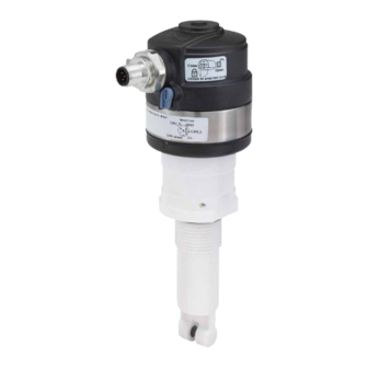
- Page 1 Type 8222 ELEMENT neutrino IO-Link / büS Conductivity meter Leitfähigkeits-Messgerät Conductivimètre Operating Instructions Bedienungsanleitung Manuel d’utilisation...
- Page 2 We reserve the right to make technical changes without notice. Technische Änderungen vorbehalten. Sous réserve de modifications techniques. © Bürkert SAS, 2022 – 2023 Operating Instructions 2310/01_EU-ML 00574525 Original EN...
-
Page 3: Table Of Contents
Type 8222 ELEMENT neutrino 1. ABOUT THIS DOCUMENT ............7 4.5. Mechanical data ..............18 4.6. Dimensions ................19 1.1. Manufacturer ................7 4.7. Conductivity sensor ..............20 1.2. Symbols used ................7 1.3. Terms and abbreviations ............8 5. INSTALLATION ..............20 2. - Page 4 Type 8222 ELEMENT neutrino 8. BÜS COMMUNICATION ............33 SENSOR – MAINTENANCE ..........42 8.1. Safety instructions ..............33 11.1. Checking the output behaviour ..........42 8.2. Setting tools and setting software ......... 33 11.2. Calibration ................43 8.3. Description of the user interface ........... 33 11.2.1.
- Page 5 Type 8222 ELEMENT neutrino 12.3. Setting the advanced parameters for identifying the GENERAL SETTINGS – MAINTENANCE ......56 device connected to büS or to a CANopen bus ....47 14.1. Restart the product ..............56 12.3.1. Entering a unique name for the device ..........47 14.2.
- Page 6 Type 8222 ELEMENT neutrino 17.2. Messages : function check ..........62 17.2.1. Message Simulation mode active ..........62 17.3. Messages : out of specification ........63 17.3.1. Message ........63 Warning: too low Conductivity 17.3.2. Message Warning: too high Conductivity .........
-
Page 7: About This Document
Type 8222 ELEMENT neutrino About this Document ABOUT THIS DOCUMENT 1.2. Symbols used The document is an important part of the product and guides DANGER the user to safe installation and operation. The information and Warns of a danger that leads to death or serious injuries. -
Page 8: Terms And Abbreviations
Type 8222 ELEMENT neutrino Safety 2.2. Safety instructions 1.3. Terms and abbreviations This safety information does not take into account any contin- The terms and abbreviations are used in this document to refer to gencies or occurrences that may arise during installation, use following definitions. - Page 9 Type 8222 ELEMENT neutrino Safety WARNING Risk of injury due to nonconforming assembly. Various dangerous situations ▶ The device must only be assembled by qualified and skilled To avoid injury, observe the following instructions: staff with the appropriate tools. ▶ Do not use the device in explosive atmospheres.
- Page 10 Type 8222 ELEMENT neutrino Safety NOTICE Elements and components that are both sensitive to electro- static discharges The device contains electronic components that are sensitive to electrostatic discharges. The components may be damaged if they are touched by an electrostatically charged person or object.
-
Page 11: Product Description
Type 8222 ELEMENT neutrino Product description PRODUCT DESCRIPTION 3.2. Product digital output The device can communicate via büS/CANopen or IO-Link. 3.1. Product overview • Devices with box in PPS and M12 connector in PA66 (see chapter 4.5) are dedicated to a use in IO-Link only. -
Page 12: Conductivity Sensor
Type 8222 ELEMENT neutrino Product description 3.3. Conductivity sensor 5. IP-Code 6. Fluid temperature The conductivity sensor is pined together with the electronic 7. Manufacturing code module and cannot be dismantled. 8. Conformity marking An alternating voltage is applied to the electrode terminals: the 9. -
Page 13: Technical Data
Type 8222 ELEMENT neutrino Technical data TECHNICAL DATA • Device used on a pipe (PS = maximum admissible pressure in bar; DN = nominal size of the pipe in mm) 4.1. Standards and directives Type of fluid Conditions The device complies with the relevant EU harmonisation leg- Fluid group 1, Article 4,... -
Page 14: Ul Certification
Type 8222 ELEMENT neutrino Technical data 4.2. Operating conditions 4.1.2. UL certification Devices with variable key PU01 or PU02 are UL-certified devices Ambient temperature –10...+60 °C and comply also with the following standards: Air humidity < 85 %, without condensation • UL 61010-1 Operating condition Continuous operation •... -
Page 15: Fluid Data
Type 8222 ELEMENT neutrino Technical data 4.3. Fluid data • Device variant with a The fluid temperature may be G 1 1/2" union nut restricted by the fluid pressure, the Process connection material of the union nut and the material of the Type S022 used. - Page 16 Type 8222 ELEMENT neutrino Technical data P (psi) P (bar) P (bar) P (psi) 217.6 217.6 Metal 188.6 188.6 159.6 159.6 130.6 101.6 130.6 72.5 101.6 43.5 72.5 43.5 +20 +40 +60 +80 +100+120T ( ° C) A: with a PVDF union nut or a G 3/4" external-threaded conductivity...
- Page 17 Type 8222 ELEMENT neutrino Technical data P (bar) P (psi) P (bar) P (psi) 217.6 217.6 Metal Metal 188.6 188.6 159.6 159.6 130.6 130.6 PVC + PP 101.6 PVC + PP 101.6 72.5 72.5 43.5 43.5 +20 +40 +60 T (°C)
-
Page 18: Electrical Data
Type 8222 ELEMENT neutrino Technical data 4.4. Electrical data 4.5. Mechanical data Operating voltage • 12...36 V DC Table 1: Materials without contact with the fluid, all device variants • Connection to main supply: per- manent through external safety Part Material extra-low voltage (SELV) and Box / seals Stainless steel, PPS / EPDM... -
Page 19: Dimensions
Type 8222 ELEMENT neutrino Technical data Table 3: Materials in contact with the fluid, all device PC and PMMA variants Part Material PA66 or Nickel- Armature of the conductivity plated brass / EPDM PVDF sensor Nickel-plated brass EPDM Pt1000 Stainless steel 1.4571 (316Ti) Electrodes of the conductivity Graphite Stainless steel sensor C = 1... -
Page 20: Conductivity Sensor
Type 8222 ELEMENT neutrino Installation 4.7. Conductivity sensor INSTALLATION Conductivity sensor C=0.01 5.1. Unscrewing the cover on the • Measurement range • 0.05...20 µS/cm connection box • Type of fluid • Ultra-pure water, pure water NOTICE Conductivity sensor C=0.1 The tightness of the device is not guaranteed when the cover •... -
Page 21: Fitting The Cover To The Connection Box
Type 8222 ELEMENT neutrino Installation → Position the polar- → Unscrew the cover on ising slots on the the connection box by cover in the axis hand. of the slots on the Polarising slots box: 3 positions are possible. Slots Fig. 7: Unscrewing the cover on the connection box... -
Page 22: Installation On The Pipe
Type 8222 ELEMENT neutrino Installation 5.3. Installation on the pipe 5.3.1. Device variant with a G 1 1/2" union nut → Choose an appropriate position in the pipe to install the WARNING fitting. In Fig. 9, prefer mounting position “1” to install a device with conductivity sensor C=0.1 or C=0.01. -
Page 23: Device Variant With A G 3/4" External-Threaded Conductivity Sensor
Type 8222 ELEMENT neutrino Installation 5.3.2. Device variant with a G 3/4" external- → Check that seal threaded conductivity sensor B is on the fitting and that it is → Check that the seal is on the external-threaded conductivity not damaged. -
Page 24: Electrical Installation
Type 8222 ELEMENT neutrino Electrical installation ELECTRICAL INSTALLATION IO-LINK COMMUNICATION To communicate in büS / CANopen or IO-Link, the following The device can be used in büS or IO-Link communication wiring must be done: systems and will automatically recognize the connected master. -
Page 25: Safety Instructions
Type 8222 ELEMENT neutrino IO-Link communication 7.1. Safety instructions 7.2. Communication table DANGER Port Class IO-Link specification V1.1.2 Risk of injury from electric shocks. Supply via IO-Link (M12 x 1, 5-pin, A-coded) ▶ Before working on the installation or product, swith off the power supply. -
Page 26: Connection To The Io-Link Master
Downloading the IODD: → Start up the hardware and software for the IO-Link master. → Go to web page country.burkert.com. → Load the sensor's device description file (IODD): see chapter 7.3 "Downloading the IODD". -
Page 27: Home Page
Type 8222 ELEMENT neutrino IO-Link communication 7.5.1. Home page Those menus are described hereafter. The main page of the IO-Link master provides information on 7.5.2. Identification the IO-Link master used and to some general information on the sensor connected. menu provides access to read-only infor- Identification mation related to the sensor. -
Page 28: Parameter
Type 8222 ELEMENT neutrino IO-Link communication 7.5.3. Parameter To handle concentration table and temperature compensation and for more described elements, please refer to the corre- Parameter menu provides access to the following sponding chapter in büS (chapter 9.1). functionalities: •... - Page 29 Type 8222 ELEMENT neutrino IO-Link communication Detailed view of the submenu: Detailed view of the submenu: Events Calibration Setting Setting • Events. Sensor connection lost Disabled Calibration. Cell constant • Enabled Calibration. Cell constant TDS • Events. Factory data failure Disabled Calibration.
- Page 30 Type 8222 ELEMENT neutrino IO-Link communication Detailed view of the submenu: Detailed view of the submenu: Simulation General settings Setting Setting • Simulation. Conductivity Inactive General settings Reboot device • Active Reset to factory Conductivity. Simulation value Status LED Mode Refer to büS,...
-
Page 31: Observation
Those messages are written in the logbook. • Device status The logbook cannot be displayed by the IO-Link master. Please use the Burkert Communicator 8920 to read the logbook (see All those submenus provide access to several categories of read- chapter 13.4). - Page 32 Type 8222 ELEMENT neutrino IO-Link communication Detailed view of the menu: Diagnostic Parameter Parameter Status. Maximum device current Sensor parameters. Cell working time Status. Minimum device current Conductivity sensor vari- Sensor information ables. Hardware version Status. Device boot counter Conductivity sensor vari- Status.
-
Page 33: Büs Communication
Type 8222 ELEMENT neutrino büS communication 8.2. Setting tools and setting software BÜS COMMUNICATION The settings can be made with the following tools: 8.1. Safety instructions • a PC with the software Type 8920 Bürkert Communicator and the büS stick. To get general information about the Type 8920 NOTICE software, refer to the Operating Instructions of the Type 8920. -
Page 34: Product Functions And Menus
Type 8222 ELEMENT neutrino büS communication Table 5: Possible login user levels 8.5. Product functions and menus The product has 2 functions and each function has 3 menus. Symbol User level Description → To access the product functions and the menus, refer to the •... -
Page 35: Sensor - Parameter
Type 8222 ELEMENT neutrino Sensor – Parameter – SENSOR PARAMETER The menu items are detailed in the following chapters: • Temperature compensation, refer to chapter 9.1. → Select device Sensor 8222. • Measure values, refer to chapter 9.2. → Go to Sensor Parameter. -
Page 36: Setting Parameter For Each Measured Values
Type 8222 ELEMENT neutrino Sensor – Parameter 9.2. Setting parameter for each Linear temperature compensation (choice Linear) measured values The linear temperature compensation may be sufficiently precise for your process whenever the temperature of your process is Measured value by the 8222 are: always > 0 °C. -
Page 37: Activating The Monitoring Of Measured Values
Type 8222 ELEMENT neutrino Sensor – Parameter 9.2.2. Activating the monitoring of measured values Because of a malfunction in the process or in the sensor, the measured values can be too high or too low. A monitored value can be: •... - Page 38 Type 8222 ELEMENT neutrino Sensor – Parameter h: Value of the hysteresis. An hysteresis value that is equal to 0 means that the device reacts as soon as a limit is reached. A: Low error limit (Error low) B: Low warning limit...
- Page 39 Type 8222 ELEMENT neutrino Sensor – Parameter Monitored value Colour of the device status indicator and Condition is in the generated message Red 1) indicator, Failure message • if the monitored value was in the LOWER warning range and the LOW ERROR value is reached.
-
Page 40: Deactivating The Monitoring Of Measured Values
Type 8222 ELEMENT neutrino Sensor – Parameter 9.2.3. Deactivating the monitoring of → Set the hysteresis value. measured values → The New settings are displayed. By default, the measured values are not monitored. The limit values and the hysteresis value are changed. -
Page 41: Deactivating The Monitoring Of An Event
Type 8222 ELEMENT neutrino Sensor – Diagnostics SENSOR – DIAGNOSTICS 9.3.2. Deactivating the monitoring of an event → Select Sensor 8222. By default, the events are monitored. → Go to Sensor Diagnostics. Do the following to deactivate it: The menu shows several categories of read only values. -
Page 42: Sensor - Maintenance
Type 8222 ELEMENT neutrino Sensor – Maintenance SENSOR – MAINTENANCE Setting Configure calibration frequency reminders → Select Sensor 8222. Calibration schedule → Go to Sensor Maintenance. Interval in days Configure numbers The menu shows the following sub menu: of days between two •... -
Page 43: Calibration
Type 8222 ELEMENT neutrino Sensor – Maintenance 11.2. Calibration • Before each calibration, correctly clean the electrodes with a suitable product. Calibrate the sensor using one of the following methods: • Set the periodicity of calibrations in the Interval in •... -
Page 44: 11.2.2. Setting Cell Constant
Type 8222 ELEMENT neutrino Sensor – Maintenance 11.3. Configure calibration schedule The message Error: out of range signals that the cell constant is out of the authorized range (< 0.008 or > 12); this may be due The calibration schedule menu gives access to several data: to either: •... -
Page 45: Resetting Calibration Data To Factory Default Value
Type 8222 ELEMENT neutrino General settings – Parameter 11.4. Resetting calibration data to GENERAL SETTINGS – PARAMETER factory default value → Select Sensor 8222. The following data can be restored to their default values: → Go to General settings Parameter. -
Page 46: Changing The Operating Mode Of The Device Status Indicator Or Switching Off The Device Status Indicator
Type 8222 ELEMENT neutrino General settings – Parameter 12.1. Changing the operating mode 12.1.2. Switching off the device status indicator of the device status indicator or switching off the device status To switch off the device status indicator, do the following: indicator →... -
Page 47: 12.2.2. Entering The Location Of The Device
Type 8222 ELEMENT neutrino General settings – Parameter 12.2.2. Entering the location of the device 12.3. Setting the advanced parameters for identifying the device connected The entered location will be shown on any display (e.g. the Com- to büS or to a CANopen bus municator software) connected to büS. -
Page 48: Changing The Transmission Speed On The Device
Type 8222 ELEMENT neutrino General settings – Parameter 12.3.2. Changing the transmission speed on 12.3.3. Changing the address of the device the device connected to a CANopen bus The transmission speed for the communication on the fieldbus The address of the device is used by büS or the CANopen (both büS or CANopen) must be the same for all the participants... -
Page 49: Setting The Digital Communication For Büs Or For A Canopen Bus
Type 8222 ELEMENT neutrino General settings – Parameter 12.3.5. Stop sending the measured process 12.3.4. Setting the digital communication for data (PDOs) to büS or to the CANopen büS or for a CANopen bus fieldbus By default, the operating mode of the digital communication is set to büS... -
Page 50: Monitoring The Supply Voltage Or The Device Temperature
Type 8222 ELEMENT neutrino General settings – Parameter 12.4. Monitoring the supply voltage or 12.4.1. Reading out the 2 error limit values the device temperature To read out the limits the supply voltage of the device should be in, do the following: The supply voltage of the device and the internal temperature of →... -
Page 51: 12.4.3. Reading Out The Hysteresis Value
Type 8222 ELEMENT neutrino General settings – Parameter 12.4.3. Reading out the hysteresis value If the diagnosics are inactive on the device, do the following to enable them: To read out the hysteresis value, do the following: → Activate the monitoring of the process values that must be →... -
Page 52: Pdos Configuration
Type 8222 ELEMENT neutrino General settings – Diagnostics 12.7. PDOs configuration GENERAL SETTINGS – DIAGNOSTICS → Select Sensor 8222. 12.7.1. Set the transmission time between 2 → Go to General settings Diagnostics. values of a PDO Setting The process data objects (PDO) are cyclic data sent from the... -
Page 53: Reading Out Device Status Information
Type 8222 ELEMENT neutrino General settings – Diagnostics 13.1. Reading out device status 13.2. Reading out büS status information information The device allows to read the following büS status information: The device allows to read out the following device status •... -
Page 54: Read The Generated Events
Type 8222 ELEMENT neutrino General settings – Diagnostics 13.4. Read the generated events To read the events that are related to the product, do the fol- lowing procedure: → Go to General settings Diagnostics. → Select Logbook. The events that are related to the product are displayed. - Page 55 Type 8222 ELEMENT neutrino General settings – Diagnostics Table 6: Description of the symbols Symbol Status Description Failure, error or fault Malfunction Function check Ongoing work on the product. For example, simulating measurement values. Out of specification At least one of the monitored parameters is outside its monitored limits.
-
Page 56: General Settings - Maintenance
Type 8222 ELEMENT neutrino General settings – Maintenance – GENERAL SETTINGS MAINTENANCE Parameter Description → Select Hardware Sensor 8222. version → Go to General settings Maintenance. Serial number Meas- → Select information. The menu shows only read-only Device urement Sensor information Firmware values. -
Page 57: Reset The Product To Its Factory Settings
Type 8222 ELEMENT neutrino General settings – Maintenance 14.2. Reset the product to its factory PROCESS DATA OBJECTS settings The participants to büS or to a CANopen fieldbus use process To reset the product to all its factory settings, do the following data objects (PDOs) to communicate the cyclic data. - Page 58 Type 8222 ELEMENT neutrino General settings – Maintenance Table 9: Device status indicator in accordance with NAMUR NE 107, edition 2006-06-12 Colour according Decimal value of Diagnostics event Meaning to NE 107 PDO3 (for a PLC) according to NE 107 Failure, error or fault Due to a malfunction of the device or its periphery, the measured values can be incorrect.
-
Page 59: Maintenance
Type 8222 ELEMENT neutrino Maintenance MAINTENANCE TROUBLESHOOTING Messages can only be generated if the diagnostics are enabled. WARNING Refer to chapter 12.5. Risk of injury due to nonconforming maintenance. When a message is generated, the following actions are carried ▶ Maintenance must only be carried out by qualified and out: skilled staff with the appropriate tools. -
Page 60: Message Factory Data Failure
Type 8222 ELEMENT neutrino Troubleshooting 17.1.2. Message 17.1.5. Message Factory data failure Error: too low Conductivity Product-status Product-status symbol symbol Possible cause Unknown cause Possible cause The Conductivity value of the water sample is is under the set limit. → Restart the product. -
Page 61: Message Error: Too Low Temperature
Type 8222 ELEMENT neutrino Troubleshooting 17.1.9. Message Error: too low TDS 17.1.7. Message Error: too low temperature Product-status Product-status symbol symbol Possible cause The TDS value of the reference electrode Possible cause The temperature value of the water is under the set limit. -
Page 62: Message Error: Too Low Resistivity
Type 8222 ELEMENT neutrino Troubleshooting 17.1.11. Message Error: too low Resistivity 17.2. Messages : function check Product-status → If the message displayed on your product is not explained in symbol the Operating Instructions, contact Bürkert. Possible cause The Resistivity of the measuring cell is under the set limit. -
Page 63: Messages : Out Of Specification
Type 8222 ELEMENT neutrino Troubleshooting 17.3.3. Message Warning: too low temperature 17.3. Messages : out of specification Product-status → If the message displayed on your product is not explained in symbol the Operating Instructions, contact Bürkert. Possible cause The temperature value of the water sample is under the set limit. -
Page 64: Warning: Too Low Tds
Type 8222 ELEMENT neutrino Troubleshooting 17.3.5. Message Warning: too low TDS 17.3.7. Message Warning: too low Resistivity Product-status Product-status symbol symbol Possible cause The TDS value of the reference electrode Possible cause The Resistivity of the measuring cell is is under the set limit. -
Page 65: Messages : Maintenance Required
Type 8222 ELEMENT neutrino Spare parts and accessories SPARE PARTS AND 17.4. Messages : maintenance ACCESSORIES required → If the message displayed on your product is not explained in CAUTION the Operating Instructions, contact Bürkert. Risk of injury and damage caused by the use of unsuitable parts. -
Page 66: Packaging, Transport
Type 8222 ELEMENT neutrino Packaging, Transport PACKAGING, TRANSPORT DISPOSAL Environmentally friendly disposal NOTICE ▶ Follow national regulations regarding disposal and Damage due to transport the environment. Transport may damage an insufficiently protected device. ▶ Collect electrical and electronic devices separately ▶... - Page 68 country.burkert.com...
Need help?
Do you have a question about the 8222 ELEMENT neutrino and is the answer not in the manual?
Questions and answers