Table of Contents
Advertisement
Quick Links
Advertisement
Table of Contents
Troubleshooting

Related Manuals for Burkert 8232


Summary of Contents for Burkert 8232
- Page 1 Type 8232 Chlorine sensor Operating Instructions...
- Page 2 We reserve the right to make technical changes without notice. Technische Änderungen vorbehalten. Sous réserve de modifications techniques. © Bürkert SAS, 2014-2016 Operating Instructions 1610/01_EU-ML 00566160 / Original EN...
-
Page 3: Table Of Contents
Type 8232 1. ABOUT THESE OPERATING INSTRUCTIONS .......5 7. INSTALLATION AND WIRING ..............13 1.1. Symbols used ..................5 7.1. Safety instructions ................. 13 1.2. Definition of the word "sensor" ..........5 7.2. Install the sensor in a pipe ............14 7.3. Preparing the sensor before installation into the 2. INTENDED USE ....................6 pipe ......................14 3. BASIC SAFETY INFORMATION ..............6 7.4. Installation of the analytical measurement chamber type 8200 ................ 18 4. GENERAL INFORMATION ................7 7.5. Installation of the sensor into the analytical... - Page 4 Type 8232 9. MAINTENANCE AND TROUBLESHOOTING ......... 23 11. PACKAGING, TRANSPORT ..............32 9.1. Safety instructions ................. 23 12. STORAGE ..................... 32 9.2. Regular maintenance operations ........... 23 13. DISPOSAL OF THE SENSOR ............. 32 9.3. Additional maintenance operations ........24 9.3.1. Checking of the tightness of the membrane cap ..24 9.3.2.
-
Page 5: About These Operating Instructions
▶ Failure to observe this warning can result in serious injury or - to the chlorine sensor type 8232 even death. - to the "trace" chlorine sensor type 8232. The marking "trace" can be read from the name plate. See chap. 5.3. english... -
Page 6: Intended Use
• the local safety regulations for which the operating company The chlorine sensor type 8232 is used to measure the free is responsible including the staff in charge of installation and chlorine concentration in water. -
Page 7: General Information
The condition governing the legal warranty is the conforming use of the sensor in observance of the operating conditions specified in these Operating Instructions. 4.3. Information on the Internet You can find the Operating Instructions and the technical data sheets regarding the sensor type 8232 at: www.burkert.com english... -
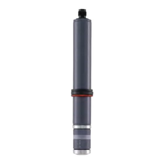
Page 8: Description
Chlorine sensor "Trace" chlorine sensor 5.1. Area of application 4-pin connector seal • The chlorine sensor type 8232 is used to measure the chlorine with cable (ordered concentration in liquids. separately) • The "trace" chlorine sensor type 8232 is used to measure the chlorine concentration in liquids at very low concentrations or to snap ring monitor the absence of chlorine. -
Page 9: Description Of The Name Plate
Type 8232 Technicaldata 5.3. Description of the name plate TECHNICAL DATA 6.1. Operating conditions Chlorine trace 8232 Ambient temperature For "trace" chlorine sensor (order code CN1H-A24p 0...+2 V 0...2 ppm 565164): 0...+40 °C max 40 °C max 0,5 bar S/N 1234 42/2016 For chlorine sensor (order codes... -
Page 10: Fluid Data
Type 8232 Technicaldata 6.3. Fluid data Chlorine sensor Chlorine sensor "Trace" chlorine sensor 568524 568523 565164 Type of medium • swimming pool water, drinking • swimming pool water, drinking water with drinking water quality water, service water, process water, sea water water • surfactants are partially •... -
Page 11: Material
Type 8232 Technicaldata 6.4. Material Materials Part Chlorine sensor 568524 Chlorine sensor 568523 "Trace" chlorine sensor 565164 Shaft Membrane Microporous hydrophilic mem- Microporous hydrophilic mem- PVC-U (semipermeable hydro- brane, PVC, stainless steel brane, PVC, stainless steel phobic membrane) 1.4571 1.4571 Seals Snap ring PETF PETF PETF Slide ring... -
Page 12: Electrical Data
Type 8232 Technicaldata 6.5. Electrical data Chlorine sensor 568524 Chlorine sensor 568523 "Trace" chlorine sensor 565164 Operating voltage 12...30 V DC 12...30 V DC 9...30 V DC (through remote controller (through remote controller (through remote controller type 8619) type 8619) type 8619) Current consumption 4 mA 4 mA 20 mA... -
Page 13: Installation And Wiring
Type 8232 Installationandwiring INSTALLATION AND WIRING WARNING Risk of injury due to non-conforming assembly. 7.1. Safety instructions ▶ The sensor must only be assembled by qualified and skilled staff with the appropriate tools. DANGER Risk of injury due to unintentional switch on of the power Risk of injury due to the nature of the electrolyte. supply or due to uncontrolled restarting of the installation. ▶ Observe the warnings on the electrolyte bottle. ▶ Protect the installation against unintentional power-up. -
Page 14: Install The Sensor In A Pipe
Type 8232 Installationandwiring 7.2. Install the sensor in a pipe NOTE Prepare the sensor. See chap. 7.3. Risk of damaging the membrane due to contamination of the membrane with solid particles and deposits, thus, leading to Install the analytical measurement chamber type 8200. See wrong measurement signals. chap. 7.4. ▶ Avoid any contact of the membrane with solid particles and Install the sensor into the analytical measurement chamber. See deposits. - Page 15 Type 8232 Installationandwiring Chlorine sensor Instructions "Trace" chlorine sensor 568524 and 568523 565164 Risk of damaging the membrane due to vacuum in the membrane cap. Vent → Before unscrewing the membrane cap, uncover the vent by lowering the Vent hose ring, to allow venting. Hose ring Hose ring On delivery, the membrane cap is not tightly screwed on the shaft.
- Page 16 Type 8232 Installationandwiring Chlorine sensor Instructions "Trace" chlorine sensor 568524 and 568523 565164 Versions with the internal holder: Carefully fill up the internal holder with the electrolyte. Make sure there is no air (bubbles) in the internal holder, else do the — filling again. Hold the shaft upright and push the working electrode carefully into the filled internal holder.
- Page 17 Type 8232 Installationandwiring Chlorine sensor Instructions "Trace" chlorine sensor 568524 and 568523 565164 → Hold the shaft upright and slowly insert it into the filled membrane cap. → Hold the membrane cap and slowly screw the shaft clockwise onto the membrane cap. If a resistance occurs because of the seal, continue screwing until the working electrode and the bottom of the membrane cap are in contact: the membrane then has a convex curvature.
-
Page 18: Installation Of The Analytical Measurement Chamber Type 8200
6...8 mm hose to the sample water source. → Connect the water outlet of the analytical measurement chamber with a 6...8 mm hose to the drain for example. For more information, refer to the datasheet of the analytical meas- urement chamber type 8200, available at: www.burkert.com. english... -
Page 19: Wiring The Sensor
Type 8232 Installationandwiring 7.6. Wiring the sensor snap ring 7.6.1. Wiring a chlorine sensor with 5-pin slide ring M12 male fixed connector seal The chlorine sensor has a 4...20 mA current output and is equipped with a 5-pin M12 male fixed connector. The sensor is electrically fed by the remote controller type 8619 the sensor is connected to. -
Page 20: Wiring A "Trace" Chlorine Sensor With 4-Pin Connector
Type 8232 Installationandwiring 7.6.2. Wiring a "trace" chlorine sensor with → Use a cable with a max. length of 30 m. 4-pin connector → Connect the sensor with the remote controller type 8619. Refer to the Operating Instructions of the related remote NOTE controller. Risk of damage to the sensor due to the power supply. negative voltage signal positive voltage signal ▶... -
Page 21: Commissioning
Type 8232 Commissioning COMMISSIONING ▶ If there are bubbles on the membrane, increase the flow rate temporarily to eliminate them. ▶ Respect the Run-in time. Negative power supply Positive power supply ▶ Calibration has to be done after the run-in time for ensur- Fig. 6 : ... -
Page 22: Commissioning Of The "Trace" Chlorine Sensor With Order Code 565164
Type 8232 Commissioning Let the sensor with order code 568524 operate for 1 hour Before commissioning: Open the measuring water outlet. let the sensor wirh order code 568523 operate for 2 hours. Slowly open the measuring water supply. A constant flow rate in Do the slope calibration with the remote controller type 8619: a range of 15...30 l/h is recommended. -
Page 23: Maintenance And Troubleshooting
Type 8232 Maintenanceandtroubleshooting MAINTENANCE AND DANGER TROUBLESHOOTING Risk of injury due to the nature of the electrolyte. ▶ Observe the warnings on the electrolyte bottle. 9.1. Safety instructions ▶ Wear gloves whose material is compatible with the electrolyte used to manipulate the sensor and the electrolyte. DANGER ▶ Do not swallow the electrolyte. -
Page 24: Additional Maintenance Operations
Type 8232 Maintenanceandtroubleshooting 9.3. Additional maintenance → Pour the old electrolyte out of the membrane cap. operations → For a sensor with an internal holder, the electrolyte of the internal holder must be changed too: 9.3.1. Checking of the tightness of the Use tweezers to remove the internal holder from the membrane cap. -
Page 25: Changing The Membrane Cap
Type 8232 Maintenanceandtroubleshooting → Fill the membrane cap with the electrolyte as described in chap. 7.3. → Calibrate the slope (see the Operating Instructions of the remote controller type 8619 the sensor is connected to). → For a sensor with an internal holder, fill the internal holder with →... -
Page 26: Troubleshooting
Type 8232 Maintenanceandtroubleshooting 9.4. Troubleshooting Remove the sensor from the analytical measurement chamber: - Unscrew the nut of the analytical measurement chamber. - Remove the nut from the sensor. 9.4.1. LED signalling on the trace sensor with order code 565164 While the sensor is still connected to the power supply, fix it with a fastener in the beaker. -
Page 27: If There Is A Problem
Type 8232 Maintenanceandtroubleshooting 9.4.2. If there is a problem Problem Possible cause Recommended actions → For the polarization time duration, see chap. 8. Slope calibration Polarization time too short cannot be done → Repeat calibration when the polarization time has elapsed. because the → Replace the membrane cap. See chap. 9.3.3. - Page 28 Type 8232 Maintenanceandtroubleshooting Problem Possible cause Recommended actions → Change the membrane. See chap. 9.3.3. Measuring signal is Membrane cracked not stable → Empty the membrane cap and fill it again with new electrolyte without Bubbles in the electrolyte bubbles. See chap. 9.3.2.
-
Page 29: If The Slope Calibration Does Not Succeed
Type 8232 Maintenanceandtroubleshooting 9.4.3. If the slope calibration does not Check the displays of the remote controller type 8619. It must be: succeed - +/– 0 mV for the "trace" chlorine sensor (order code 565164) If the slope calibration cannot be done: • because of the deviation of the measuring value from the DPD- - +/–... -
Page 30: Checking The Signal
Type 8232 Maintenanceandtroubleshooting Read the value displayed by the remote controller type 8619. Stir continuously using the sensor still connected to the remote controller type 8619) for at least 5 min. - If the displayed value approaches 0 V for the "trace" chlorine sensor (order code 565164) If the sensor signal increases, the sensor is working correctly. -
Page 31: Spare Parts And Accessories
Type 8232 Sparepartsandaccessories 10. SPARE PARTS AND 10.2. Accessories ACCESSORIES Accessory Order code 4-pin connector with cable 565385 ATTENTION 5-pin female M12 connector with 2 m cable 438680 Risk of injury and/or damage caused by the use of unsuitable Photometer MD100, measuring range parts. 566393 0,01...6 ppm Incorrect accessories and unsuitable spare parts may cause injuries and damage the sensor and the surrounding area. -
Page 32: Packaging, Transport
Type 8232 Packaging,transport 11. PACKAGING, TRANSPORT To store the sensor: Unscrew the membrane cap from the shaft. NOTE Rinse the reference electrode in clean water: do not touch nor Damage due to transport rub the electrodes. Let it dry in a place free of dust. - Page 34 www.burkert.com...
Need help?
Do you have a question about the 8232 and is the answer not in the manual?
Questions and answers