Bürkert 8202 Operating Instructions Manual
Element
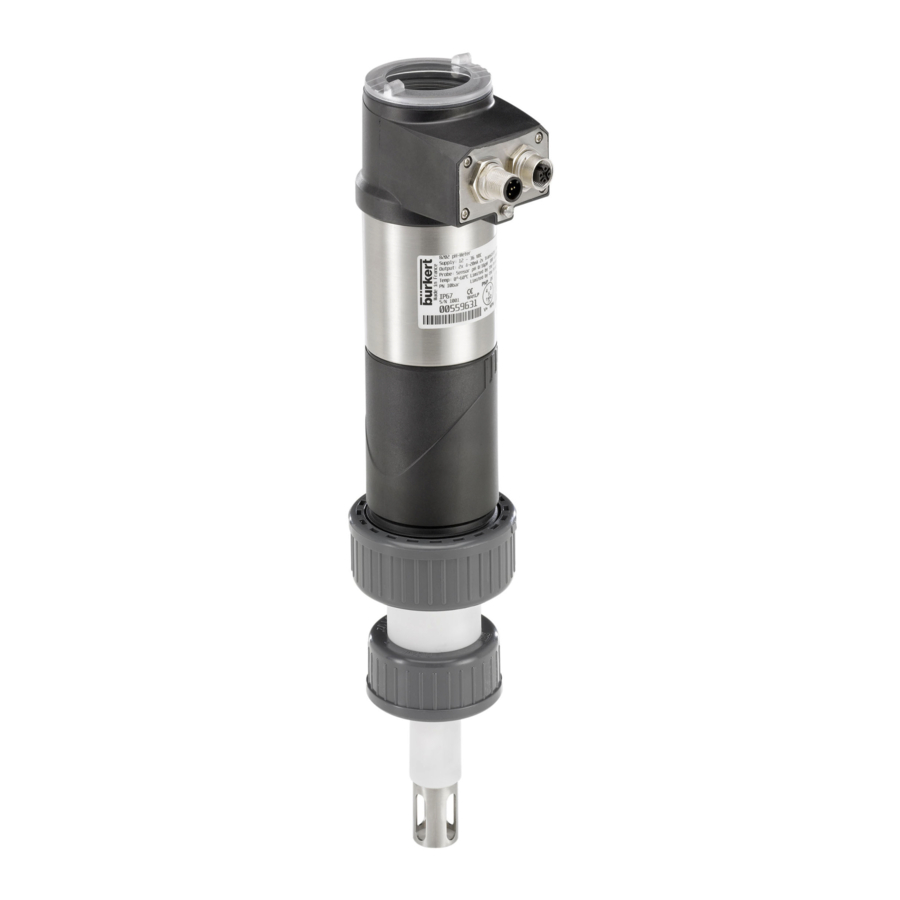
ph- or redox-meter
Hide thumbs
Also See for 8202:
- Quick start manual (118 pages) ,
- Operating instructions manual (82 pages) ,
- Operating instructions manual (76 pages)

Related Manuals for Bürkert 8202


Summary of Contents for Bürkert 8202
-
Page 1: Operating Instructions
Type 8202 ELEMENT pH- or redox-meter pH- oder Redox-Messgerät pH- ou redox-mètre Operating Instructions Bedienungsanleitung Manuel d‘utilisation... - Page 2 We reserve the right to make technical changes without notice. Technische Änderungen vorbehalten. Sous réserve de modifications techniques. © Bürkert SAS, 2008 - 2016 Operating Instructions 1603/4_EU-ML 00560329 / Original_FR...
-
Page 3: Table Of Contents
..................10 4.2 Warranty conditions ................................10 information on the internet ............................10 4.3 Description ....................................11 Area of application ................................11 5.1 General description ................................11 5.2 5.2.1 Construction of the 8202 .........................11 5.2.2 pH or Redox ("ORP") probe ......................11 Description of the name plate .............................12 5.3 5.4 Available versions ................................12 technicAl DAtA .....................................13 6.1 conditions of use ................................13 conformity to standards and directives .........................13 6.2... - Page 4 Typ 8202 ELEMENT Assembly ......................................19 7.1 safety instructions ................................19 7.2 removing the cover ................................19 7.3 mounting the cover ................................20 7.4 mounting the display module ............................20 7.5 removing the display module .............................21 7.6 mounting the probe into the holder (without fluid) ..................21 7.7 mounting the electronic module to the sensor holder (without fluid) ...........22 instAllAtion AnD WirinG ..............................23 safety instructions ................................23 8.1 installation onto the pipe ..............................24 8.2 electrical wiring ..................................26 8.3 8.3.1 Assembling the male or female connector (accessories) ............27 8.3.2...
- Page 5 Typ 8202 ELEMENT 9.11 Knowing the parameters menu ...........................43 9.11.1 Transferring data from one device to another ................43 9.11.2 Setting the date and time .........................44 9.11.3 Modifying the PARAM menu access code ...................44 9.11.4 Restoring the default parameters of the Process level and the outputs .......45 9.11.5...
- Page 6 Typ 8202 ELEMENT mAintenAnce AnD troubleshootinG ........................66 10.1 safety instructions ................................66 10.2 cleaning the device ................................66 10.2.1 Cleaning the pH/Redox ("ORP") probe ..................67 10.3 replacing the probe ................................67 10.4 replacing the seal of the sensor holder ........................68 10.5 solving a problem ................................70 spAre pArts AnD Accessories ............................75 pAcKAGinG, trAnsport ................................76 storAGe ......................................76 DisposAl of the proDuct ..............................76 English...
-
Page 7: About This Manual
▶ Whatever the version of the device, this manual must be read and understood. 1.1 Definition of the word "device" The word "device" used within this manual refers to the pH or "ORP" (Redox) transmitter type 8202 ELEMENT. 1.2 Validity of the manual The manual is valid for the devices from the version V2. -
Page 8: Intended Use
Typ 8202 ELEMENT Aboutthismanual note Warns against material damage. ▶ Failure to observe this warning may result in damage to the device or system. Indicates additional information, advice or important recommendations. Refers to information contained in this manual or in other documents. ▶ Indicates an instruction to be carried out to avoid a danger, a warning or a possible risk. -
Page 9: Basic Safety Information
Typ 8202 ELEMENT Basicsafetyinformation bAsic sAfETy iNforMATioN This safety information does not take into account: • any contingencies or occurrences that may arise during assembly, use and maintenance of the device. • the local safety regulations that the operator must ensure the staff in charge of installation and maintenance observe. -
Page 10: General Information
The condition governing the legal warranty is the conforming use of the device in observance of the operating conditions specified in this manual. 4.3 information on the internet You can find the user manuals and technical data sheets regarding the transmitter type 8202 at: www.burkert.com English... -
Page 11: Description
Typ 8202 ELEMENT Description DEscripTioN 5.1 Area of application The device is intended solely for the measurement of: • the pH in clean liquids or liquids containing solids, sulphides or proteins. • or the oxidation reduction potential ("ORP") in clean liquids or liquids containing solids, sulphides or proteins which may present low conductivity. -
Page 12: Description Of The Name Plate
The resulting voltage is the oxidation reduction potential ("ORP"). 5.3 Description of the name plate 1. Type of device, parameter measured and 8202 pH/ORP Transmitter Supply: 14-36V 40W Max version Output: 1x 4-20mA 2x Trans 1A Max Cell: pH -2/16 ORP +-2V 120mm PG13.5... -
Page 13: Technical Data
Typ 8202 ELEMENT Technicaldata TEchNicAL DATA 6.1 conditions of use Ambient temperature -10 to +60 °C ( without pH or Redox ("ORP") probe) Air humidity < 85%, non condensated Protection rating according to IP65 and IP67 with connectors plugged in and tightened and electronic EN 60529 module cover fully sealed 6.2... -
Page 14: Mechanical Data
EPDM PVC or PVDF pH or Redox ("ORP") refer to the related probe manual PVDF Stainless steel 1.4571 (316Ti) Fig. 2 Materials used in the transmitter type 8202 (without the probe) 6.4 Dimensions of the 8202 → Please refer to the technical data sheets regarding the transmitter type 8202, available at: www.burkert.com English... -
Page 15: Fluid Data
Typ 8202 ELEMENT Technicaldata 6.5 fluid data pipe diameter DN25 to DN110 (DN15 to DN20 under specific conditions) type of fitting Adapter S022 nut between the 8202 and the fitting G 1 1/2'' internal thread max. fluid temperature The fluid temperature may be restricted by the probe used (see the related instruction manual), by the pressure of the fluid and the material of the adapter S022 •... - Page 16 Typ 8202 ELEMENT Technicaldata • A: application range of a 8202 with a PVDF nut P (bar) P (psi) • B: application range of a 8202 with a PVC nut 217.6 PVDF The measures have been made at an ambient 188.6 temperature of 60 °C 159.6...
-
Page 17: Electrical Data
Typ 8202 ELEMENT Technicaldata 6.6 Electrical data power supply • Version with 3 outputs • 14-36 V DC, filtered and regulated • Version with 4 outputs • 12-36 V DC, filtered and regulated characteristics of the power source (not supplied) • limited energy source (in accordance to UL 61010-1, of the ul versions paragraph 9.3) -
Page 18: Data Of Connectors And Cables
Typ 8202 ELEMENT Technicaldata 6.7 Data of connectors and cables number of fixed connectors type of connectors 1 male M12 fixed connector 5-pin female M12 connector (not supplied). For the M12 connector with order code 917116, use a shielded cable: • diameter: 3 to 6.5 mm • wire cross section: max. 0.75 mm... -
Page 19: Assembly
Typ 8202 ELEMENT Assembly AssEMbLy 7.1 safety instructions Danger risk of injury due to electrical voltage. ▶ Shut down and isolate the electrical power source before carrying out work on the system. ▶ Observe all applicable accident protection and safety regulations for electrical equipment. Warning risk of injury due to non-conforming assembly. ▶ The device must only be assembled by qualified and skilled staff with the appropriate tools. -
Page 20: Mounting The Cover
Typ 8202 ELEMENT Assembly 7.3 Mounting the cover → Check that there is a seal on the housing and that it is not damaged. Replace it if necessary. → Grease the seal if necessary, using a component compatible with the seal material. → [1] Set the cover to ensure that the 4 grooves of the cover match with the 4 pins of the housing. -
Page 21: Removing The Display Module
Typ 8202 ELEMENT Assembly 7.5 removing the display module → Remove the cover if necessary (see chap. 7.2). → Turn the module by ca. 20° counter clockwise. Once unlocked, the module is raised slightly by the spring action. 20° → Remove the module from its housing. -
Page 22: Mounting The Electronic Module To The Sensor Holder (Without Fluid)
Typ 8202 ELEMENT Assembly 7.7 Mounting the electronic module to the sensor holder (without fluid) → Check that the probe is mounted into the sensor holder (see chap. 7.6). → Check that seal "A" on the holder is in good condition. Replace it if necessary (see chap. 11) → Clean connectors "B" and "C" for connection of the pH/redox ("ORP") probe with alcohol to avoid measurement errors. -
Page 23: Installation And Wiring
Typ 8202 ELEMENT Installationandwiring iNsTALLATioN AND WiriNG 8.1 safety instructions Danger risk of injury due to electrical voltage. ▶ Disconnect the electrical power for all the conductors and isolate it before carrying out work on the system. ▶ If a 12-36 V DC or a 14-36 V DC powered version is installed either in a wet environment or outdoors, all the electrical voltages must be of max. -
Page 24: Installation Onto The Pipe
Typ 8202 ELEMENT Installationandwiring Warning risk of injury due to non-conforming installation. Non-conforming commissioning could lead to injuries and damage the device and its surroundings. ▶ Before commissioning, make sure that the staff in charge have read and fully understood the contents of the manual. ▶ In particular, observe the safety recommendations and intended use. - Page 25 Typ 8202 ELEMENT Installationandwiring The probe must always be immersed in the fluid to prevent it drying out. → Once the transmitter has been calibrated, remove the electronic module from the sensor holder as shown Fig. 14. → Unscrew the nut between the electronic module and the sensor holder.
-
Page 26: Electrical Wiring
Typ 8202 ELEMENT Installationandwiring → If the sensor holder is tight, insert the electronic module back onto the sensor holder as shown in Fig. 16. → Check that the electrical contacts are in good condition and clean them with a brush if necessary. -
Page 27: Assembling The Male Or Female Connector (Accessories)
Typ 8202 ELEMENT Installationandwiring 8.3.1 Assembling the male or female connector (accessories) → Unscrew the nut [1] on the body [4]. → Insert the cable into the nut [1], the cable clamp [2] and the seal [3], and then into the body [4]. → Strip 20 mm of the cable. -
Page 28: Wiring A Version With A Single M12 Fixed Connector
Typ 8202 ELEMENT Installationandwiring Devices such as valves, pumps,... Power supply Pipes in plastic Fig. 19 Equipotentiality skeleton diagram with pipes in plastic 8.3.3 Wiring a version with a single M12 fixed connector Transistor output 1 V+ (14-36 V DC) Transistor output 2 Fig. 20 Pin assignment of the fixed connector on a version with a single M12 fixed connector pin for the female m12 connector available as an accessory (order code 438680) colour of the wire brown white blue black grey Load 1 (solenoid valve for instance) - Page 29 Typ 8202 ELEMENT Installationandwiring Load 1 (solenoid valve for instance) white brown black grey blue Load 2 (solenoid valve for instance) Power supply 14-36 V DC Fig. 22 PNP wiring of both transistor outputs (software setting "PNP/source", see chap. 9.11.8), of a version with 1 M12 fixed connector 4-20mA input at external 4-20mA input at external device device blue brown brown...
-
Page 30: Wiring A Version With 2 M12 Fixed Connectors
Typ 8202 ELEMENT Installationandwiring 8.3.4 Wiring a version with 2 M12 fixed connectors Transistor output 1 Transistor output 2 (12-36 V DC) (12-36 V DC) Current output 2 Current output 1 female fixed connector male fixed connector Fig. 26 Pin assignment of the male and female M12 fixed connectors Connect the power supply for the transmitter to the male fixed connector; the supply is then transferred internally to pins 1 and 3 of the female fixed connector in order to ease wiring of the load to the female fixed connector. - Page 31 Typ 8202 ELEMENT Installationandwiring Load 2 (solenoid valve for instance) Load 1 (solenoid valve for instance) white white brown blue grey blue Power supply 12-36 V DC Fig. 28 PNP wiring of both transistor outputs of a version with 2 fixed connectors (software setting "PNP/source", see chap. 9.11.8) 4-20mA input at external device 4-20mA input at external device brown brown...
- Page 32 Typ 8202 ELEMENT Installationandwiring Load 1 Load 2 white white brown blue brown grey black black 12-36 V DC 4-20mA input at external 4-20mA input at external device device Power supply Fig. 31 NPN wiring of both transistor outputs and wiring of both current outputs in sinking mode, on a version with 2 fixed connectors (software setting "NPN/sink", see chap. 9.11.8) Load 1 Load 2 white white blue brown...
-
Page 33: Adjustment And Commissioning
Typ 8202 ELEMENT Adjustmentandcommissioning ADjusTMENT AND coMMissioNiNG • The settings can only be done on a device with a display module. • Do not remove the display module while making the settings on the device. 9.1 safety instructions Warning risk of injury due to non-conforming adjustment. Non-conforming adjustment could lead to injuries and damage the device and its surroundings. -
Page 34: Using The Navigation Button
Typ 8202 ELEMENT Adjustmentandcommissioning configuration level This level comprises 5 menus: Menu title Relevant icon "Param": see chap. 9.11 This is when the device is be- ing parame- tered........ "Calib": see chap. 9.12 "Diagnostic": see chap. 9.13 "Test": see chap. 9.14 "Info": see chap. 9.15 9.3... - Page 35 Typ 8202 ELEMENT Adjustmentandcommissioning you want to... press... • ...access the Configuration level • ...display the Param menu for at least 2 sec., from any screen of the Read level ...browse in the menus of the Configuration level • next menu: • previous menu: ...access the menu displayed...
-
Page 36: Using The Dynamic Functions
Typ 8202 ELEMENT Adjustmentandcommissioning 9.4 using the dynamic functions you want to... choose..go back to the Process level, without validating the modifica- dynamic function "MEAS" tions made ...validate the input dynamic function "OK" ...go back to the parent menu dynamic function "BACK" ... abort the current operation and go back to the parent menu dynamic function "ABORT"... -
Page 37: Knowing The Display
Typ 8202 ELEMENT Adjustmentandcommissioning 9.7 Knowing the display The display module is only equipped on some versions of the device. It can be ordered as an accessory. 9.7.1 Knowing the icons and LEDs Green LED: shows that Yellow LED: shows that transistor 1 is switched the device is energized... -
Page 38: Knowing The Display At The Power-Up Of The Device
Typ 8202 ELEMENT Adjustmentandcommissioning 9.7.2 Knowing the display at the power-up of the device When the device is switched on or the display module mounted on the electronic module, the display indicates the software version of the display. The display then shows the first screen in the Process level: See chap. 9.11.5 and 9.11.6 to choose the data to be displayed in the Process level. -
Page 39: Accessing The Configuration Level
Typ 8202 ELEMENT Adjustmentandcommissioning 9.9 Accessing the configuration level > 2s Param This is when the This is This is when the when the device is be- Any display of the device is be- device is be- ing parame- ing parame- tered........ tered.... ing parame- System .... -
Page 40: Knowing The Structure Of The Menus On The Configuration Level
Typ 8202 ELEMENT Adjustmentandcommissioning 9.10 Knowing the structure of the menus on the configuration level See chap. 9.9 to access the Configuration level. If an “upload” has been done with this module Param System Up/Download Download Downl. Yes/No Upload Yes/No Upload This is This is when the when the device is be-... - Page 41 Typ 8202 ELEMENT Adjustmentandcommissioning Param Outputs HWMode sink/NPN source/PNP This is This is when the when the device is be- device is be- ing parame- ing parame- tered.... tered............ PVar: AC1/AC2 mV_pH mV_ORP TempF TempC INPUT 4mA: 20mA: INPUT Filter:...
- Page 42 Typ 8202 ELEMENT Adjustmentandcommissioning Calib Sensor Probe Calib. Temp. Auto Constant Calibration 1st point If pH probe 2nd point? Rinse 2nd point Cal.Result Probe constant Offset: INPUT INPUT Span: Calib. interval Last cal. date VALUE INPUT Interval Temperature INPUT Diagnostic System Code...
-
Page 43: Knowing The Parameters Menu
Typ 8202 ELEMENT Adjustmentandcommissioning Test System Code 0*** Confirm code 0*** Outputs AC1: INPUT AC2: INPUT TR1: OFF/ON TR2: OFF/ON Sensor PVar: mV_pH mV_ORP TempF TempC Value: INPUT Info Error MESSAGE Warning MESSAGE Maintenance MESSAGE Smiley MESSAGE Software Main READ Sensor READ... -
Page 44: Setting The Date And Time
Typ 8202 ELEMENT Adjustmentandcommissioning Param System Up/Download Download Downl. Yes/No Upload Yes/No Upload This is This is when the when the device is be- device is be- ing parame- ing parame- tered.... tered............ The following data can be transferred from one device to another device of the same type: •... -
Page 45: Restoring The Default Parameters Of The Process Level And The Outputs
Typ 8202 ELEMENT Adjustmentandcommissioning 9.11.4 restoring the default parameters of the process level and the outputs See chap. 9.9 to access the Parameters menu. The following data can be restored to their default values: • user settings in the menu PARAM (except the date, the time, the contrast level and the brightness of the display), •... -
Page 46: Displaying The Lowest And Highest Values Measured
Typ 8202 ELEMENT Adjustmentandcommissioning FILTER: choose the filter level for the measurement values displayed on the line selected. Three filter levels are proposed: "slow", "fast" or "none". Fig. 36 shows the 3 filter curves. 150 ms 30 s "slow" "fast" "none" Fig. 36 ... -
Page 47: Setting The Display Contrast And Brightness
Typ 8202 ELEMENT Adjustmentandcommissioning 9.11.7 setting the display contrast and brightness See chap. 9.9 to access the Parameters menu. On a version with a single M12 fixed connector and if the power supply is lower than 16 V, do not increase the backlight over 14%, to not influence the 4-20mA current output. -
Page 48: Setting The Parameters Of The Current Outputs
Typ 8202 ELEMENT Adjustmentandcommissioning 9.11.9 setting the parameters of the current outputs See chap. 9.9 to access the Parameters menu. Warning risk of injury due to wrong adjustment. ▶ Before setting the parameters for the display, choose the type of probe mounted on the transmitter (see chap. 9.11.11). The 2nd current output "AC2" is only available on a version with 2 fixed connectors. -
Page 49: Setting The Parameters Of The Transistor Outputs
Typ 8202 ELEMENT Adjustmentandcommissioning FILTER: choose the level of damping for the fluctuations of the current value for each current output. Three damping levels are proposed: "slow", "fast" or "none". The damping for the current outputs is similar to the damping of the display (see Fig. 36). - Page 50 Typ 8202 ELEMENT Adjustmentandcommissioning MODE: choose the operating mode for transistor output 1 or transistor output 2 (see Fig. 38 and Fig. 39). LOW: enter the low switching threshold value for transistor output 1 or transistor output 2 (see Fig. 38 and Fig.
-
Page 51: Setting The Sensor Parameters
Typ 8202 ELEMENT Adjustmentandcommissioning 9.11.11 setting the sensor parameters The monitoring (see chap. 9.13.2) of the redox ("ORP") sensor is impossible if the measurement mode is set to "asymmetrical". See chap. 9.9 to access the Parameters menu. Param Sensor Type: This is This is when the... -
Page 52: Knowing The Calibration Menu
Typ 8202 ELEMENT Adjustmentandcommissioning 9.12 Knowing the calibration menu 9.12.1 Activating/deactivating the hold function See chap. 9.9 to access the Calibration menu. Calib System Hold Hold:Disable Hold:Enable If the mode "Hold" is activated and if there is a power interruption, then, when the device restarts, the mode "Hold" is automatically deactivated. -
Page 53: Adjusting The Current Outputs
Typ 8202 ELEMENT Adjustmentandcommissioning 9.12.3 Adjusting the current outputs See chap. 9.9 to access the Calibration menu. On a version with a single M12 fixed connector and if the power supply is lower than 16 V, before adjusting the current output, make sure the backlight is lower as 14% (see chap. 9.11.7). - Page 54 Typ 8202 ELEMENT Adjustmentandcommissioning Calib Sensor Probe CalibTemperat. Auto Constant Calibration 1st point if pH probe 2nd point? Rinse 2nd point Cal.Result Probe constant Offset: INPUT INPUT Span: Calib. interval Last cal. date VALUE INPUT Interval Temperature INPUT CALIB TEMPERAT.: choose the type of temperature compensation for the calibration process: either the tem- perature measured (select "Auto") or a fixed value (select "constant"...
- Page 55 Typ 8202 ELEMENT Adjustmentandcommissioning • In order not to interrupt the process, activate the HOLD function (see chap. 9.12.1). • Before each calibration, correctly clean the electrode with a suitable product. • In a 2-point calibration, the buffer solutions used must be at the same temperature.
- Page 56 Typ 8202 ELEMENT Adjustmentandcommissioning Detailed procedure for the 1- or 2-points calibration of the ph probe Calib Sensor Probe Calibration → Immerse the clean sensor in the first buffer solution; the transmitter alternately displays: • the measured pH of the solution • the measured temperature of the solution 1st point 7.100 pH →...
-
Page 57: Calibrating The Redox- ("Orp"-) Sensor
Typ 8202 ELEMENT Adjustmentandcommissioning At the end of calibration of the pH sensor, two types of messages may be displayed: Possible Recommended Message "span" value "offset" value cause action → "Warning:Span/ 50 mV/pH < span < 53 mV/pH -60 mV < Offset < -35 mV... - Page 58 Typ 8202 ELEMENT Adjustmentandcommissioning CALIB TEMPERAT.: choose the type of temperature compensation for the calibration process: either the tem- perature measured (select "Auto") or a fixed value (select "constant" then enter reference temperature). → Calibrate the sensor using one of the following methods: - CALIBRATION: calibrate the Redox ("ORP") sensor in 1 point (see details hereafter).
- Page 59 Typ 8202 ELEMENT Adjustmentandcommissioning Detailed procedure for the 1-point calibration of the oxidation reduction potential ("orp") sensor Calib Sensor Probe Calibration → Immerse the clean sensor in the buffer solution; the transmitter alter- nately displays: • the measured potential difference of the solution • the measured temperature of the solution Calibration 465.0 mV →...
-
Page 60: Entering An Offset For The Temperature Measurement
Typ 8202 ELEMENT Adjustmentandcommissioning 9.12.6 Entering an offset for the temperature measurement See chap. 9.9 to access the Calibration menu. The temperature transmitted by the Pt1000 probe may be corrected. This correction value is the temperature offset. Calib Sensor Temperature INPUT Enter the temperature offset (input limits: ±5 °C) 9.13... - Page 61 Typ 8202 ELEMENT Adjustmentandcommissioning To be warned when an electrode has too low or too high an impedance: → activate monitoring on this electrode in the function "activate", then → set an impedance range (in MW for the pH electrode and in kW for the reference electrode of the pH/redox ("ORP") probe) outside of which the transmitter generates a "warning"...
-
Page 62: Monitoring The Fluid Temperature
Typ 8202 ELEMENT Adjustmentandcommissioning 9.13.3 Monitoring the fluid temperature See chap. 9.9 to access the Diagnostic menu. The function allows for monitoring the fluid temperature and configure the behaviour of the device if the param- etered ranges are exceeded. A malfunction in your process or the built-in temperature probe may be indicated either by too low or too high a fluid temperature or by an incorrect temperature measurement. -
Page 63: Knowing The Test Menu
Typ 8202 ELEMENT Adjustmentandcommissioning 9.14 Knowing the Test menu 9.14.1 Modifying the Test menu access code See chap. 9.9 to access the Test menu. Test System Code 0*** Confirm code 0*** Enter the new Confirm the new code code If the default code (0000) is entered, the code will not be requested to access the menu. -
Page 64: Checking The Outputs Behaviour
Typ 8202 ELEMENT Adjustmentandcommissioning 9.14.3 checking the outputs behaviour See chap. 9.9 to access the Test menu. • Make sure that the mode "Hold" is deactivated (see chap. 9.12.1). • The icon is displayed in place of the icon as soon as the check for the correct working of an output has started. -
Page 65: Reading The Software Versions
Typ 8202 ELEMENT Adjustmentandcommissioning 9.15.2 reading the software versions See chap. 9.9 to access the Info menu. Info Main READ Software READ Sensor The function allows for reading: • the software version of the acquisition / conversion board ("Main") for the measurable variables, • the software version of the sensor ("Sensor"). -
Page 66: Maintenance And Troubleshooting
Typ 8202 ELEMENT Maintenanceandtroubleshooting MAiNTENANcE AND TroubLEshooTiNG 10.1 safety instructions Danger risk of injury due to electrical voltage. ▶ Disconnect the electrical power for all the conductors and isolate it before carrying out work on the system. ▶ If a 12-36 V DC or a 14-36 V DC powered version is installed either in a wet environment or outdoors, all the electrical voltages must be of max. -
Page 67: Cleaning The Ph/Redox ("Orp") Probe
Typ 8202 ELEMENT Maintenanceandtroubleshooting 10.2.1 cleaning the ph/redox ("orp") probe Refer to the instruction manual delivered with the probe used. 10.3 replacing the probe Danger risk of injury due to electrical voltage. ▶ Disconnect the electrical power for all the conductors and isolate it before carrying out work on the system. ▶ If a 12-36 V DC or a 14-36 V DC powered version is installed either in a wet environment or outdoors, all the electrical voltages must be of max. -
Page 68: Replacing The Seal Of The Sensor Holder
Typ 8202 ELEMENT Maintenanceandtroubleshooting → Remove the electronic module by pulling it straight out. There may be a slight resistance due to the seal. → Unscrew the probe using a suitable wrench. → Remove it carefully from the holder. → Clean any fluid projections on the electrical contacts on the holder. - Page 69 Typ 8202 ELEMENT Maintenanceandtroubleshooting → Unscrew the nut between the sensor holder and the electronic module. → Remove the electronic module by pulling it straight out. There may be a slight resistance due to the seal. → Remove the used seal "A" from the holder.
-
Page 70: Solving A Problem
Typ 8202 ELEMENT Maintenanceandtroubleshooting 10.5 solving a problem red current transistor icon message dis- possible cause recommended action output output played in the info menu → ON 22 mA depending "E:Sat. ORP Stage" The pH or redox Check the correct wiring of ("ORP") value is the earth points. "E:Sat. pH Stage"... - Page 71 Typ 8202 ELEMENT Maintenanceandtroubleshooting red current transistor icon message dis- possible cause recommended action output output played in the info menu → ON 22 mA depending "TR COM Measure" The acquisition/con- Switch the power supply version module of off then on again. thresholds the process values is →...
- Page 72 Typ 8202 ELEMENT Maintenanceandtroubleshooting red current transistor icon message displayed possible cause recommended action output output in the info menu → ON 22 mA depending on "E:Impedance Ref" The impedance of the Go into the "Sensor" thresholds reference electrode is function of the Diag- out of range. nostic menu to read...
- Page 73 Typ 8202 ELEMENT Maintenanceandtroubleshooting red current transistor icon message displayed in possible cause recommended action output output the info menu → OFF 4-20 mA Switched "W:Impedance Ref" The impedance of the Go into the "Sensor" reference electrode is function of the Diag- out of range. nostic menu to read...
- Page 74 Typ 8202 ELEMENT Maintenanceandtroubleshooting red current transistor icon message dis- possible cause recommended action output output played in the info menu → 4-20 mA Switched "M:Calib. Date" A calibration is due. Calibrate the sensor (chap. 9.12.4). The periodicity of the cal- ibrations is set within the "INTERVAL" function of the "CALIB INTERVAL"...
-
Page 75: Spare Parts And Accessories
Typ 8202 ELEMENT Sparepartsandaccessories spArE pArTs AND AccEssoriEs caution risk of injury and/or damage caused by the use of unsuitable parts. Incorrect accessories and unsuitable replacement parts may cause injuries and damage the device and the sur- rounding area. ▶ Use only original accessories and original replacement parts from Bürkert. spare part orde code Seal in EPDM, Ø 46x2 mm, for the sensor holder... -
Page 76: Packaging, Transport
Typ 8202 ELEMENT Packaging,Transport pAcKAGiNG, TrANsporT note Damage due to transport Transport may damage an insufficiently protected device. ▶ Transport the device in shock-resistant packaging and away from humidity and dirt. ▶ Do not expose the device to temperatures that may exceed the admissible storage temperature range. - Page 78 www.burkert.com...
Need help?
Do you have a question about the 8202 and is the answer not in the manual?
Questions and answers