
Related Manuals for Burkert ELEMENT 8228


Summary of Contents for Burkert ELEMENT 8228
- Page 1 Type 8228 ELEMENT Inductive conductivity meter Induktives Leitfähigkeitsmessgerät Conductimètre inductif Operating Instructions Bedienungsanleitung Manuel d‘utilisation...
- Page 2 We reserve the right to make technical changes without notice. Technische Änderungen vorbehalten. Sous réserve de modifications techniques. © Bürkert SAS, 2014 – 2022 Operating Instructions 2211/05_EU-ML 00565588 / Original EN...
-
Page 3: Table Of Contents
Type 8228 Contents ABOUT THE OPERATING INSTRUCTIONS ..................6 1.1 Definition of the word "device" ....................6 1.2 Validity of the Operating Instructions ..................6 1.3 Symbols used ..........................6 INTENDED USE ............................7 BASIC SAFETY INFORMATION ......................7 GENERAL INFORMATION ........................9 4.1 Manufacturer's address and international contacts ..............9 4.2 Warranty conditions ........................9 4.3 Information on the Internet ......................9 DESCRIPTION ............................10 5.1 Area of application ........................10 5.2 Knowing the device ........................10 5.3... - Page 4 Type 8228 INSTALLATION AND WIRING .......................20 8.1 Safety instructions ........................20 8.2 Installing a device variant with G2" nut in a pipe ..............21 8.3 Installing a device variant with 2" clamp in a pipe ................22 8.4 Wiring ............................23 8.4.1 Assembling the male or female connector (see chapter 11) ........24 8.4.2 Equipotentiality of the installation ................24 8.4.3 Device variant with a single M12 fixed connector ............25 8.4.4 Device variant with 2 M12 fixed connectors ...............28 ADJUSTMENT AND START-UP ......................31 9.1 Safety instructions ........................31 9.2 Knowing the operating levels ....................31 9.3 Using the navigation button .....................32 9.4 Using the dynamic functions .....................34...
- Page 5 Type 8228 9.12 Knowing the Calibration menu ....................51 9.12.1 Activating/deactivating the Hold function ..............51 9.12.2 Modifying the Calibration menu access code ............51 9.12.3 Adjusting the current outputs ..................52 9.12.4 Calibrating the sensor ....................52 9.12.5 Entering an offset for the temperature measurement ..........57 9.13 Knowing the Diagnostic menu ....................57 9.13.1 Modifying the Diagnostic menu access code ............57 9.13.2 Monitoring the fluid conductivity ................57 9.13.3 Monitoring the fluid temperature ................58 9.14 Knowing the Test menu ......................59 9.14.1 Modifying the Test menu access code ...............59 9.14.2 Checking the outputs functions..................60 9.14.3...
-
Page 6: About The Operating Instructions
Type 8228 About the Operating Instructions ABOUT THE OPERATING INSTRUCTIONS The Operating Instructions describes the entire life cycle of the device. Please keep the Operating Instruc- tions in a safe place, accessible to all users and any new owners. The Operating Instructions contains important safety information. Failure to comply with these instructions can lead to hazardous situations. Pay attention in particular to the chapters "Basic safety information" and "Intended use". ▶ Irrespective of the device variant, read the Operating Instructions. If you do not understand the content of the Operating Instructions then contact Bürkert. ▶ When the symbol is marked inside or outside the device, carefully read the Operating Instructions. Definition of the word "device" The word "device" used within these Operating Instructions refers to the Type 8228 ELEMENT conductivity meter. Validity of the Operating Instructions The Operating Instructions are valid for the Type 8228 ELEMENT conductivity meter version V2. Mention V2 is given on the device Type-label. Refer to chapter 5.3. Symbols used DANGER Warns against an imminent danger. ▶ Failure to observe this warning can result in death or in serious injury. WARNING Warns against a potentially dangerous situation. -
Page 7: Intended Use
Type 8228 About the Operating Instructions ▶ Indicates an instruction to be carried out to avoid a danger, a warning or a possible risk. → Indicates a procedure to be carried out. Indicates the result of a specific instruction. INTENDED USE Use of the device that does not comply with the instructions could present risks to people, nearby installations and the environment. The Type 8228 ELEMENT conductivity meter is intended for the measurement of the conductivity of liquids. ▶ Use this device in compliance with the characteristics and start-up and use conditions specified in the contractual documents and in the Operating Instructions. ▶ Do not use the device for security applications. ▶ Only operate a device in perfect working order. ▶ Store, transport, install and operate the device properly. ▶ Only use the device as intended. BASIC SAFETY INFORMATION This safety information does not take into account any contingencies or occurrences that may arise during installation, use and maintenance of the device. The operating company is responsible for the respect of the local safety regulations including staff safety. Risk of injury due to electrical voltage. ▶ Before carrying out work on the system or the device, disconnect the electrical power for all the con- ductors and isolate it. ▶ If the device is installed either in a wet environment or outdoors, all the electrical voltages must be of max. 35 V DC. - Page 8 About the Operating Instructions Risk of burns due to high fluid temperatures. ▶ Use safety gloves to handle the device. ▶ Before opening the pipe, stop the circulation of fluid and drain the pipe. ▶ Before opening the pipe, make sure the pipe is completely empty. Risk of injury due to the nature of the fluid. ▶ Respect the regulations on accident prevention and safety relating to the use of dangerous fluids. Various dangerous situations To avoid injury: ▶ Do not to use the device in explosive atmospheres. ▶ Do not to use the device in an environment incompatible with the materials it is made of. ▶ Do not use fluid that is incompatible with the device materials. Find the compatibility chart on our home- page: country.burkert.com ▶ Do not to subject the device to mechanical stress. ▶ Do not to make any modifications to the device. ▶ Prevent any unintentional power supply switch-on. ▶ Only qualified and skilled staff may carry out the installation and maintenance work. ▶ Ensure a defined or controlled restart of the process after a power supply interruption. ▶ Observe the general technical rules. NOTICE Elements / Components sensitive to electrostatic discharges ▶ The device contains electronic components that are sensitive to electrostatic discharges. The compo- nents may be damaged if they are touched by an electrostatically charged person or object. In the worst case scenario, the components are instantly destroyed or disabled as soon as they are activated.
-
Page 9: General Information
Type 8228 General information GENERAL INFORMATION Manufacturer's address and international contacts To contact the manufacturer of the device, use following address: Bürkert SAS Rue du Giessen BP 21 F-67220 TRIEMBACH-AU-VAL The addresses of our international sales offices are available on the internet at: country.burkert.com Warranty conditions The condition governing the legal warranty is the conforming use of the device in observance of the oper- ating conditions specified in these Operating Instructions. Information on the Internet You can find the Operating Instructionss and technical data sheets for Type 8228 at: country.burkert.com english... -
Page 10: Description
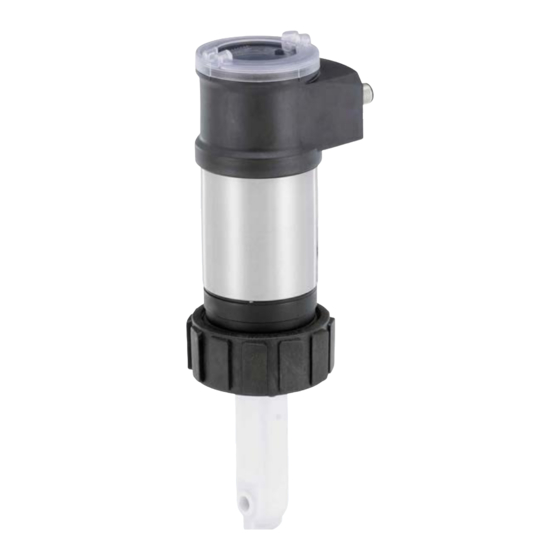
Type 8228 Description DESCRIPTION Area of application The device is intended to measure the conductivity. Thanks to one or two fully adjustable transistor outputs, the device can be used to switch a solenoid valve, activate an alarm and, thanks to one or two 4...20 mA current outputs, establish one or two control loops. Knowing the device The device comprises: A: an electrical housing which can include a display module. The display module has a navigation button to read and/or configure the parameters of the device. The display module is not delivered with all the device variants but it is available as an accessory (see chapter 11). 1: Grounding screw B: an electronic module for the acquisition and the conversion of the measurable variables: - acquisition of the conductivity in µS/cm, - acquisition of the temperature, - calculation of the conductivity at a temperature of 25 °C, - conversion of the conductivity into a resistivity at 25 °C in Ohm/ C: a conductivity sensor comprised of: - a pair of magnetic coils, - a sensor holder in PP, PVDF or PEEK equipped with an inte- grated temperature probe. The conductivity sensor is pined together with the electronic module and cannot be dismantled. The conductivity sensor comprises a temperature probe to com- pensate the temperature when measuring the conductivity. The device operates on a 3 wire system and needs a 12...36 V DC power supply. -
Page 11: Type Label
Type 8228 Description Type label 8228 Inductive Conductivity Meter Supply: 12-36V 40W max. Output: 1x 4-20mA 1xTrans 700mA max. Cell: PEEK Range 100 µS/cm - 2 S/cm Process: Temp -15 to 130°C PN 10, limited by fitting material and fluid temp. IP65-IP67 W41MN 2:NPN/PNP1... -
Page 12: Technical Data
Type 8228 Technical data TECHNICAL DATA Conditions of use –10...+60 °C Ambient temperature Air humidity < 85%, without condensation Indoor and outdoor ▶ Protect the device against electromagnetic interference, ultra- violet rays and, when installed outdoors, the effects of the climatic conditions. IP-Code IP67 and IP65 , according to IEC / EN 60529 Mating connectors must be wired, plugged,and tightened. not evaluated by UL Housing lid must be fully tightened and locked Continuous operation Operating condition Equipment mobility Fixed device Degree 2 according to UL/EN 61010-1 Degree of pollution Installation category... -
Page 13: Ul Certification
Type 8228 Technical data • Device used on a vessel (PS = maximum admissible pressure) Type of fluid Conditions Fluid group 1, Article 4, Paragraph 1.a.i PS ≤ 200 bar Fluid group 2, Article 4, Paragraph 1.a.i PS ≤ 1000 bar Fluid group 1, Article 4, Paragraph 1.a.ii PS ≤ 500 bar Fluid group 2, Article 4, Paragraph 1.a.ii PS ≤ 1000 bar 6.2.2 UL certification The devices with variable key PU01 or PU02 are UL certified devices and comply also with the following standards: • UL 61010-1 • CAN/CSA-C22.2 n°61010-1 Identification on the device Certification Variable key UL recognized PU01 Measuring UL listed PU02 Equipment ® EXXXXXX 6.2.3 FDA approval The following device variants have an FDA approval: device variant with a condictivity-sensor holder in PVDF, with an EPDM seal or an FKM seal. -
Page 14: Dimensions
+140 T (°C) Fig. 2 : Dependency between the fluid temperature and the fluid pressure, device variants with a conductivity- sensor armature in PVDF, PP or PEEK, and device inserted in a Type S020 fitting in stainless steel Dimensions → Please refer to the technical data sheets related to the device avalaible at: country.burkert.com english... -
Page 15: Materials
• Device variant with G2" nut • PVDF, FKM • PP, FKM • PEEK, FKM • Device variant with 2"-clamp process connection • PEEK, EPDM Adapter for clamp stainless steel 316L 1.4404 G2" process connection 2"-clamp process connection Nickel-plated brass silicone (or stainless steel) Stainless steel PPS CF 30 EPDM Stainless steel Stainless PC, PPA steel EPDM PVDF or PP or PEEK PEEK only Fig. 3 : Materials of the device • Materials of fittings: Please refer to the technical data sheets of the related fittings, avalaible at: country.burkert.com english... -
Page 16: Electrical Data
Type 8228 Technical data Electrical data Operating voltage • 12...36 V DC • connection to main supply: permanent through external safety extra-low voltage (SELV) and through limited power source (LPS) • filtered and regulated • oscillation rate: ±10 % Power source • Limited power source according to UL/EN 60950-1 standards (not supplied) • or limited energy circuit according to UL/EN 61010-1, Paragraph 9.4 Current consumption • without the consumption of the • max. 1 W (max. 25 mA at 12 V DC; starting current ~100 mA) current outputs and the transistor outputs • with the consumption of the current • max. 40 W (max. 1 A for the transistor outputs) outputs and the transistor outputs Transistor output: polarized • type • NPN (/sink) or PNP(/source). Through wiring and through software setting •... -
Page 17: Assembly
Type 8228 Assembly ASSEMBLY Safety instructions DANGER Risk of injury due to electrical voltage. ▶ Before carrying out work on the system or the device, disconnect the electrical power for all the con- ductors and isolate it. ▶ Observe all applicable accident protection and safety regulations for electrical equipment. WARNING Risk of injury due to non-conforming assembly. ▶ The device must only be assembled by qualified and skilled staff with the appropriate tools. Risk of injury due to unintentional switch on of power supply or uncontrolled restart of the installation. ▶ Avoid unintentional activation of the installation. ▶ Guarantee a set or controlled restarting of the process after any intervention on the device. Removing the housing lid NOTICE The tightness of the device is not guaranteed when the housing lid is removed. ▶ Prevent the projection of liquid inside the housing. The device may be damaged if a metal component comes into contact with the electronics. ▶ Prevent contact of the electronics with a metallic item. → [1] Turn the housing lid counter- clockwise with an angle of about 15° to unlock it. → [2] Remove the housing lid. If the housing lid grips to the housing: →... -
Page 18: Mounting The Housing Lid
Type 8228 Assembly Mounting the housing lid → Check that there is a seal on the housing and that it is not damaged. Replace the seal if necessary. → Grease the seal if necessary, using a component compatible with the seal material. → [1] Set the housing lid to ensure that the 4 grooves of the housing lid match with the 4 pins of the housing. → [2] Turn the housing lid clockwise with an angle of about 15° to lock it. Fig. 5 : Closing the housing lid Mounting the display module → Remove the housing lid (see chapter 7.2). 20° → Set the display module at an angle of about 20° in relation to the desired position. → The display module can be mounted in 4 different posi- tions, at 90° intervals. →... -
Page 19: Dismounting The Display Module
Type 8228 Assembly Dismounting the display module → Remove the housing lid (see chapter 7.2). → Turn the module by ca. 20° counterclockwise. Once unlocked, the module is raised slightly by the spring 20° action. → Remove the module from its housing. Fig. 7 : Dismounting the display module english... -
Page 20: Installation And Wiring
Type 8228 Installation and wiring INSTALLATION AND WIRING Safety instructions Risk of injury due to electrical voltage. ▶ Before carrying out work on the system or the device, disconnect the electrical power for all the con- ductors and isolate it. ▶ If the device is installed either in a wet environment or outdoors, all the electrical voltages must be of max. 35 V DC. ▶ All equipment connected to the device shall be double insulated with respect to the mains according to the standard UL/EN 61010-1. ▶ Observe all applicable accident protection and safety regulations for electrical equipment. Risk of injury due to high pressure in the installation. ▶ Before any intervention in the installation, stop the circulation of fluid, cut off the pressure and drain the pipe. ▶ Before any intervention in the installation, make sure there is no pressure in the pipe. ▶ Observe the dependency between the fluid temperature and the fluid pressure. Risk of burns due to high fluid temperatures. ▶ Use safety gloves to handle the device. ▶ Before opening the pipe, stop the circulation of fluid and drain the pipe. ▶ Before opening the pipe, make sure the pipe is completely empty. Risk of injury due to the nature of the fluid. ▶ Respect the regulations on accident prevention and safety relating to the use of dangerous fluids. WARNING Risk of injury due to non-conforming installation. -
Page 21: Installing A Device Variant With G2" Nut In A Pipe
Type 8228 Installation and wiring WARNING Risk of injury if the dependency between the fluid pressure and the fluid temperature is not respected. ▶ Observe the dependency between the fluid temperature and the fluid pressure for the device. Refer to chapter 6.3. ▶ Observe the dependency between the fluid temperature and the fluid pressure for the fitting used. Refer to the Operating Instructions of the fitting used. Installing a device variant with G2" nut in a pipe The device is put into a Type S020 fitting that is mounted on the pipe. → Mount the fitting on the pipe. Obey the instructions of the Operating Instructions of the fitting used. Fig. 8 : Positions for the mounting on the pipe Tank without mixing Tank with mixing device device Fig. 9 : Positions for the mounting on a container →... -
Page 22: Installing A Device Variant With 2" Clamp In A Pipe
Type 8228 Installation and wiring → Make sure the seal (mark 2) is on the conductivity sensor. → Make sure that the material of the seal is compatible with the fluid to be measured. → Put the nut (mark 5) on the fitting. → Put the snap ring (mark 3) into the groove (mark 4). → Engage the device (mark 1) into the fitting. → Screw the nut (mark 5) manually on the device. Fig. 10 : Installation of a device variant with G2" nut in a Type S020 fitting → Wire according to instructions in chapter 8.4. Installing a device variant with 2" clamp in a pipe DANGER Risk of injury if the stainless steel adapter of the device is loose. -
Page 23: Wiring
Type 8228 Installation and wiring → Install the device in the fitting as shown in Fig. 11. → Select a seal (mark 4) that is compatible with the 2" clamp con- nection of the device and with the fluid. → Put the seal (mark 4) on the fitting (mark 5). → Insert the device (mark 1) in the fitting (mark 5): - the electrical connections must be parallel to the pipe, - the sensor (mark 2) must be positioned in the fluid vein. → Tighten the clamp collar (mark 3) by hand. Fig. 11 : Installation of a device variant with 2" clamp process connection in the pipe → Wire according to instructions in chapter 8.4. Wiring DANGER Risk of injury due to electrical voltage. ▶... -
Page 24: Assembling The Male Or Female Connector (See Chapter 11)
Type 8228 Installation and wiring 8.4.1 Assembling the male or female connector (see chapter 11) → Unscrew the nut [1] on the body [4]. → Insert the cable into the nut [1], the cable clamp [2] and the seal [3], and then into the body [4]. → Strip 20 mm of the cable. → Cut the central wire (earth) so that its length is equal to 11.5 mm. → Expose 5.5 mm of the wires on the stripped cable. → Put each wire into the appropriate terminal of the terminal block [5] (see chapter 8.4.3 or 8.4.4). → Tighten the terminal block [5] wired to the body [4]. → Tighten the connector nut [1]. Fig. 12 : Assembling the M12 multi-pin connector (not provided) 8.4.2 Equipotentiality of the installation To ensure the equipotentiality of the installation (power supply - device - medium):... -
Page 25: Device Variant With A Single M12 Fixed Connector
Type 8228 Installation and wiring 12-36 V DC Power supply Plastic pipe Devices such as valves, pumps,... Fig. 14 : Equipotentiality skeleton diagram with pipes in plastic 8.4.3 Device variant with a single M12 fixed connector Transistor output (TR1) 0 V V+ (12...36 V DC) Current output (AC1) Fig. 15 : Pin assignment of the male fixed connector on a device variant with a single M12 fixed connector Pin of the M12 female cable available as an accessory (article number 438680) Colour of the wire brown... - Page 26 Type 8228 Installation and wiring Load white brown blue green/yellow or grey Power supply 12-36 V DC Fig. 17 : PNP wiring of the transistor output of a device variant with 1 fixed connector (parameter setting "PNP/ source") 4...20 mA input at exter- nal instrument brown black green/yellow or grey blue...
- Page 27 Type 8228 Installation and wiring Load white blue brown green/yellow or grey black 4...20 mA input at exter- Power supply nal instrument 12-36 V DC Fig. 20 : NPN wiring of the transistor output and and wiring in sinking mode of the current output of a device variant with 1 fixed connector (parameter setting "NPN/sink") Load white...
-
Page 28: Device Variant With 2 M12 Fixed Connectors
Type 8228 Installation and wiring 8.4.4 Device variant with 2 M12 fixed connectors Male fixed connector Female fixed connector Transistor output 1 (TR1) Transistor output 2 (TR2) 0 V V+ (12...36 V DC) 0 V V+ (12...36 V DC) Current output 2 (AC2) Current output 1 (AC1) Fig. 22 : Pin assignment of the male and female M12 fixed connectors Connect the power supply for the device to the male fixed connector; the supply is then transferred internally to pins 1 and 3 of the female fixed connector in order to ease wiring of the load to the female fixed connector. Pin of the female or male M12 cables available as accessories Colour of the wire (article number 438680 respectively 559177) brown white... - Page 29 Type 8228 Installation and wiring 4...20 mA input at ex- 4...20 mA input at ternal instrument external instrument brown brown black black blue green/yellow or grey Power supply 12-36 V DC Fig. 25 : Wiring of both current outputs in sinking mode, on a device variant with 2 fixed connectors (parameter setting "NPN/sink") 4...20 mA input at 4...20 mA input at external instrument...
- Page 30 Type 8228 Installation and wiring Load 1 Load 2 white white blue brown blue black black green/yellow or grey 4...20 mA input at 4...20 mA input at external instrument external instrument 12-36 V DC Power supply Fig. 28 : PNP wiring of both transistor outputs and wiring of both current outputs in sourcing mode, on a device variant with 2 fixed connectors (parameter setting "PNP/source") english...
-
Page 31: Adjustment And Start-Up
Type 8228 Adjustment and start-up ADJUSTMENT AND START-UP • The settings can only be done on a device with a display module. • Do not remove the display module while making the settings on the device. Safety instructions WARNING Risk of injury due to non-conforming adjustment. Non-conforming adjustment could lead to injuries and damage the device and its surroundings. ▶ The operators in charge of operating must have read and understood the contents of the Operating Instructions. ▶ In particular, observe the safety recommendations and intended use. ▶ The device/installation must only be operated by suitably trained staff. WARNING Danger due to non-conforming start-up. Non-conforming start-up could lead to injuries and damage the device and its surroundings. ▶ Before start-up the device, calibrate the conductivity sensor. Refer to chapter 9.12.4. ▶ Before start-up, make sure that the staff in charge have read and fully understood the contents of the Operating Instructions. ▶ In particular, observe the safety recommendations and intended use. ▶ The device / the installation must only be commissioned by suitably trained staff. ▶ Set the correction factor of the fitting used (see chapter 9.12.4). Knowing the operating levels The device has 2 operating levels: Process level This level is used:... -
Page 32: Using The Navigation Button
Type 8228 Adjustment and start-up Configuration level This level comprises 5 menus: Menu title Relevant icon "Param": see chapter 9.11 This is when the device is be- ing parame- tered........ "Calib": see chapter 9.12 "Diagnostic": see chapter 9.13 "Test": see chapter 9.14 "Info": see chapter 9.15 Using the navigation button Symbolised by Symbolised by in these in these Operat- Operating Instructions ing Instructions Symbolised by in these Operating Instructions Symbolised by in these... - Page 33 Type 8228 Adjustment and start-up You want to... Press..browse in the Process level • next screen: • previous screen: • ...access the Settings level • ...display the Param menu for at least 2 sec., from any screen of the Process level ...browse in the menus of the Settings level • next menu: • previous menu: ...access the menu displayed ...browse in the menu functions • next function: • previous function: ...select the highlighted function ...browse in the dynamic functions bar (MEAS, • next function: BACK, ABORT, OK, YES, NO) • previous function: ...confirm the highlighted dynamic function ...modify a numerical value - increment the figure selected - decrement the figure selected - select the previous figure - select the next figure...
-
Page 34: Using The Dynamic Functions
Type 8228 Adjustment and start-up Using the dynamic functions You want to... Choose..go back to the Process level, without confirming the dynamic function "MEAS" modifications made ...validate the input dynamic function "OK" ...go back to the parent menu dynamic function "BACK" ... abort the current operation and go back to the parent dynamic function "ABORT" menu ...answer the question asked dynamic function "YES" or "NO" Entering a numerical value (example) Modify each digit of the numerical value using: to increase the digit selected, to decrease the digit selected. Calib.Temp Select the digit at the extreme left of the numerical value +0.000°C with then Select the digit at the extreme allocate the "+" or right of the numerical value with "-" sign to the nu- then move the decimal... -
Page 35: Browsing In A Menu (Example)
Type 8228 Adjustment and start-up Browsing in a menu (example) Title of the current menu, sub-menu or The icon identifies the function. current menu Param The arrow indicates that some more This is when the functions are available which can be device is be- ing parame- tered........ Line1 displayed by using Line2 Highlighted function Contrast The arrow indicates that some more functions are available which can be MEAS ABORT OK displayed by using Dynamic functions (accessible through and... -
Page 36: Knowing The Display At The Power-Up Of The Device
Type 8228 Adjustment and start-up Icon Meaning and alternatives Sensor in good condition, fluid conductivity and fluid temperature within the set ranges. If the monitoring of the conductivity and/or the fluid temperature and/or the fluid conductivity has been activated, the alternative icons in this position are: • , associated with : see chapter 9.13.2, chapter 9.13.3, chapter 9.15.1, chapter 10.3 • , associated with : see chapter 9.13.2, chapter 9.13.3, chapter 9.15.1, chapter 10.3 The device is measuring. The alternative icons in this position are: • flashing: function HOLD is active (see chapter 9.12.1) HOLD • : running check that the outputs are working and behaving correctly (see chapter 9.14.2 and chapter 9.14.3) "maintenance" message; See chapter 9.12.4, chapter 9.15.1, chapter 10.3 "warning" message; See chapter 9.11.10, chapter 9.13.2, chapter 9.13.3, chapter 9.15.1, chapter 10.3 "error" message; See chapter 9.11.9, chapter 9.13.2, chapter 9.13.3, chapter 9.15.1, chapter 10.3 9.7.2 Knowing the display at the power-up of the device When the device is powered up or the display module mounted on the electronic module, the display indi- cates the software version of the display module. The display then shows the first screen of the Process level: See chapter 9.11.5 and 9.11.6 to choose the data to be dis- played in the Process level. -
Page 37: Knowing The Process Level
Type 8228 Adjustment and start-up Knowing the Process level CondS First view of the 1.423 mS/cm Process level. TempC 55 °C Display of the current outputs. 18.3 mA 7.5 mA CondS Zoom on the value 1.423 in the first line. Zoom on the value of the first 18.3 mA current output. Zoom on the value in TempC the second line. °C Zoom on the value of the 7.5 mA second current output. -
Page 38: Accessing The Configuration Level
Type 8228 Adjustment and start-up Accessing the Configuration level > 2s Param This is when the This is Any view of the This is when the when the device is be- device is be- device is be- ing parame- ing parame- tered.... System tered.... -
Page 39: Knowing The Structure Of The Menus Of The Configuration Level
Type 8228 Adjustment and start-up 9.10 Knowing the structure of the menus of the Configuration level See chapter 9.9 to access the Configuration level. If an "upload" has been succesfully made Param System Up/Download Download Downl. Yes/No with this module Upload Yes/No Upload This is This is when the when the device is be- device is be- ing parame- ing parame- Date... - Page 40 Type 8228 Adjustment and start-up Param Outputs HWMode sink/NPN source/PNP This is This is when the when the device is be- device is be- ing parame- ing parame- tered.... tered............ PVar: CondS AC1/AC2 CondR TempC TempF TDSppm INPUT 4mA: 20mA: INPUT...
- Page 41 Type 8228 Adjustment and start-up Calib System Hold Hold:Disabled Hold:Enabled Code 0*** Confirm code 0*** Outputs AC1/AC2 INPUT 20mA INPUT Calibrate Zero Sensor Probe Zero Calib. Point? Processing Calibration INPUT RESULT Cell constant INPUT K-fitting INPUT Cell cst. TDS INPUT Calib interval Last cal. date READ Interval INPUT Teach special Start temp INPUT Stop temp...
- Page 42 Type 8228 Adjustment and start-up Test System Code 0*** Confirm code 0*** Outputs AC1: INPUT AC2: INPUT TR1: OFF/ON TR2: OFF/ON Sensor PVar: CondS CondR TempC TempF TDSppm Value: INPUT Info Error MESSAGE Warning MESSAGE Mainten. MESSAGE Smiley MESSAGE Software Main READ READ Sensor...
-
Page 43: Knowing The Parameters Menu
Type 8228 Adjustment and start-up 9.11 Knowing the Parameters menu 9.11.1 Transferring data from one device to another See chapter 9.9 to access the Parameters menu. This function is only possible with a display module with software version V2. → On the device, check the software version in the menu "Info -> Software -> Main". • The software version of the display module is displayed when the display module is powered up. • Function "DOWNLOAD" is only present if an "UPLOAD" has been successfully carried out. • Never interrupt a data transfer else the device could be damaged. The compensation curve determined with the function TEACH SPECIAL (see chapter 9.12.4) cannot be transferred to another device. Param System Up/Download Download Downl. Yes/No Upload Yes/No Upload This is This is when the when the device is be-... -
Page 44: Modifying The Param Menu Access Code
Type 8228 Adjustment and start-up 9.11.3 Modifying the PARAM menu access code See chapter 9.9 to access the Parameters menu. Param System Code 0*** Confirm code 0*** Enter the new Enter the new code a This is This is when the when the device is be- device is be- code second time ing parame- ing parame- tered.... -
Page 45: Setting The Data Displayed In The Process Level
Type 8228 Adjustment and start-up 9.11.5 Setting the data displayed in the Process level See chapter 9.9 to access the Parameters menu. Param Display Line1 / Line2: Enabled Disabled This is This is when the when the device is be- device is be- PVar: CondS ing parame- ing parame- tered.... -
Page 46: Displaying Of The Lowest And Highest Values Measured
Type 8228 Adjustment and start-up 9.11.6 Displaying of the lowest and highest values measured See chapter 9.9 to access the Parameters menu. Param Display Min/Max: Status: Enabled Disabled This is This is when the when the device is be- PVar: CondS device is be- ing parame- ing parame- tered.... -
Page 47: Choosing The Output Wiring Mode
Type 8228 Adjustment and start-up 9.11.8 Choosing the output wiring mode See chapter 9.9 to access the Parameters menu. Param Outputs HWMode source/PNP sink/NPN This is when the This is device is be- when the ing parame- device is be- tered.... ing parame- ....tered........ The wiring mode is the same for all outputs. →... -
Page 48: 9.11.10 Setting The Parameters Of The Transistor Outputs
Type 8228 Adjustment and start-up 4mA: choose the value of the process value (previously selected), associated with a current of 4 mA, for each current output. 20mA: choose the value of the process value (previously selected), associated with a current of 20 mA, for each current output. FILTER: choose the level of damping for the fluctuations of the current value for each current output. Three filter levels are proposed: slow, fast or none. The damping for the current outputs is similar to the damping of the display (see Fig. 32, chapter 9.11.5). MODE DIAG.: choose to emit a current of 22 mA on the current output selected when an “error” event related to diagnostics (see chapter 9.13.2 and 9.13.3) is generated by the device or allow the current output to operate normally (choose "none"). An "error" event linked to a malfunction of the device is always indicated by the generation of a 22 mA current, whatever the adjustmant made in the function "MODE DIAG.". See also chapter "10.3 Solving a problem". 9.11.10 Setting the parameters of the transistor outputs See chapter 9.9 to access the Parameters menu. PVar: CondS Outputs TR1 / TR2 Param CondR This is This is when the when the device is be- TempC... -
Page 49: Choosing The Type Of Temperature Compensation
Type 8228 Adjustment and start-up CONTACT: choose the type of off-position (normally open, NO, or normally closed, NC) of transistor output 1 or transistor output 2 (see Fig. 34 and Fig. 35). DELAY: choose the value of the time delay prior to switching, for each transistor output. Switching only occurs if one of the thresholds, high or low (functions “High” or “Low”), is exceeded for a duration longer than this time delay (see Fig. 34 and Fig. 35). The time delay before switching is applicable to both output thresholds. Hysteresis operating The change of status is done when a threshold is detected (increasing measured value: threshold high (function High) to be detected; decreasing measured value: threshold low (function Low) to be detected). NO = normally open NC = normally closed contact contact process value process value Low High Low High Fig. 34 : Hysteresis operating Window operating The change of status occurs whenever one of the thresholds is detected. NO = normally open NC = normally closed contact contact process value process value Low High Low High Fig. 35 : Window operating 9.11.11... - Page 50 Type 8228 Adjustment and start-up • or according to a curve defined especially for your process (choice “Special”) using the “Teach special” function in the “Calibration - Sensor” menu, “Probe” function (see chapter 9.12.4). If the choice "Special" is set for this function: • and the compensation curve has not been determined (see chapter 9.12.4), the measurements of the conductivity are not compensated in temperature. • If the compensation curve has been determined (see chapter 9.12.4), it is not uploaded with the function UPLOAD (see chapter 9.11.1). • or according the concentration table (choice “Concentration table”, available in option) selected in the function “Concentration”. Param Sensor Comp.: None Linear:0.000% INPUT This is This is when the when the device is be- NaCl device is be- ing parame- ing parame- tered....
-
Page 51: Knowing The Calibration Menu
Type 8228 Adjustment and start-up 9.12 Knowing the Calibration menu 9.12.1 Activating/deactivating the Hold function See chapter 9.9 to access the Calibration menu. Calib System Hold Hold:Disable Hold:Enable If the mode "Hold" is activated and if there is a power interruption, then, when the device restarts, the mode "Hold" is automatically deactivated. The mode "Hold" is used to carry out maintenance work without interrupting the process. To activate the mode HOLD: → access the "HOLD" function; → choose "enabled" and confirm by "OK". To deactivate the mode HOLD: → access the "HOLD" function; →... -
Page 52: Adjusting The Current Outputs
Type 8228 Adjustment and start-up 9.12.3 Adjusting the current outputs See chapter 9.9 to access the Calibration menu. Calib Outputs AC1 / AC2 4mA: INPUT INPUT 20mA: 4mA: adjust the current output 1 or current output 2 for 4 mA. When the "4mA" function is selected, the device generates a current of 4 mA: measure the current emitted by the 4...20 mA output using a multimeter and enter the value given by the multimeter in the function “AC1.4mA” or “AC2.4mA”. 20mA: adjust the current output 1 or current output 2. for 20 mA When the "20mA" function is selected, the device generates a current of 20 mA: measure the current emitted by the 4...20 mA output using a multimeter and enter the value given by the multimeter in the function “AC1.20mA” or “AC2.20mA”. 9.12.4 Calibrating the sensor DANGER Risk of injury due to electrical voltage. ▶ Observe all applicable accident protection and safety regulations for electrical equipment. Risk of injury due to the nature of the fluid. ▶ Respect the regulations on accident prevention and safety relating to the use of dangerous fluids. See chapter 9.9 to access the Calibration menu. Calibrate Zero Calib Sensor Probe Zero Calib. - Page 53 Type 8228 Adjustment and start-up The accuracy of the conductivity measurements is influenced by: • the drift of the zero point of conductivity. Correct the drift of the zero point with the function ZERO CALIB. To be done if the conductivity of the air measured by the conductivity sensor is higher than 10 µS/cm (see "Calibrate the zero point of conductivity (“Zero Calib.” function in the “Probe” menu)", page 54). • the conductivity cell constant: - determine the cell constant of the sensor used with the function CALIBRATION (this calibration updates the last calibration date in the “Last cal. date” function of the CALIB INTERVAL sub-menu hereafter). See "Calibrate the conductivity sensor (“Calibration” function in the “Probe” menu)", page 55, - or enter the cell constant (marked on the calibration certificate of the device) in the function CELL CON- STANT. The entering of the cell constant does not update the last calibration date in the “Last cal. date” function of the CALIB INTERVAL sub-menu. The function CELL CONSTANT makes it also possible to read the value of the constant which has been determined with the function CALIBRATION. • the correction factor of the fitting. Enter the correction factor related to the fitting S020 used in the function K-FITTING. The correction factor depends on the shape, the material and the diameter of the fitting used. The following table gives the correction factors of the fittings S020. Tab. 1: Correction factors of the fittings S020, depending on the shape, the material and the DN of the fittings Fittings with true union Fittings with internal Measurement...
- Page 54 Type 8228 Adjustment and start-up TEACH SPECIAL: define the temperature compensation curve specific to your process. The curve thus determined and memorised is used by the device when you choose “Special” in the “Comp.” function in the menu “Param - Sensor” (see chapter 9.11.11). See also "Define the temperature compensation curve spe- cific to your process (“Teach special” function in the “Probe” menu)", page 56. The compensation curve determined with the function TEACH SPECIAL cannot be transferred to another device with the function DOWNLOAD (see chapter 9.11.1). Calibrate the zero point of conductivity (“Zero Calib.” function in the “Probe” menu) • In order not to interrupt the process, activate the HOLD function (see chapter 9.12.1). • Before each calibration, fully clean the conductivity sensor with a special cleaning agent, then rince and dry. If the value of air conductivity measured is higher than 10 µS/cm, readjust the device, holding the sensor in the air (zero point of conductivity of the device). Calib Sensor Probe Zero Calib. Calibrate Zero Point? → Put the cleaned and dried conductivity sensor in contact with the ambient air. The device automatically calibrates Processing the zero point of conductivity in less than 1 second. → Save or not the calibration result by Save modified choosing "Yes" or "No". data? english...
- Page 55 Type 8228 Adjustment and start-up Calibrate the conductivity sensor (“Calibration” function in the “Probe” menu) Calibration consists in determining the C constant specific to each conductivity sensor using a solution with a known conductivity. • In order not to interrupt the process, activate the HOLD function (see chapter 9.12.1). • Before each calibration, fully clean the conductivity sensor with a special cleaning agent. • To calibrate a conductivity sensor off-line, put the sensor in the center of a beaker of min. 8 cm in diameter. • To calibrate a conductivity sensor off-line, make sure there are no air bubbles in the hole of the conductivity sensor. • Set the periodicity of calibrations in the "Interval" function in the sub-menu "Calib interval" (see page 53): each time a calibration is due, the device generates a "maintenance" event and a "warning" event. Calib Sensor Probe Calibration → Immerse the clean conductivity sensor in the solution with a known conductivity. The device alternately displays: • the measured conductivity of the solution • the measured temperature of the solution → Enter the conductivity, at Calibration the fluid temperature, of 5.023 µS/cm the reference solution used (marked on the bottle or 5.000 µS/cm measured using a reference...
- Page 56 Type 8228 Adjustment and start-up Define the temperature compensation curve specific to your process (“Teach special” function in the “Probe” menu) Calib Sensor Probe Teach special Start temp +40.00 °C → Enter the value for the start of the temperature range for which the compensation curve must be determined. Stop temp +55.00 °C The fluid temperature range (T–; T+) must be entered in such a way that the difference between T– and T+ is greater than 8 °C. The message "Error: Temp span at least 8 °C" is displayed if the dif- ference between the range start and end values is less than 8 °C. → Enter the value of the end of the temperature range for which the com- pensation curve must be determined. → Before confirming to begin the procedure, check that the fluid temper- ature is below 25 °C and T–. Processing... 1.234 mS When the function HOLD is deactivated (chapter 9.12.1), the device determines the compensation curve with 10 points and alternately displays both the measured conductivity and the measured temperature of the solution. • Immerse the sensor in the solution and progressively reheat: - from T– to 25 °C if T– < T+ < 25 °C - from T– to T+ if T– < 25 °C < T+ - from 25 °C to T+ if 25 °C < T– < T+ •...
-
Page 57: Entering An Offset For The Temperature Measurement
Type 8228 Adjustment and start-up 9.12.5 Entering an offset for the temperature measurement See chapter 9.9 to access the Calibration menu. The temperature transmitted by the temperature probe may be corrected. This correction value is the tem- perature offset. Calib Sensor Temperature INPUT Enter the temperature offset (±5 °C) 9.13 Knowing the Diagnostic menu 9.13.1 Modifying the Diagnostic menu access code See chapter 9.9 to access the Diagnostic menu. Diagnostic System Code 0*** Confirm code 0*** Enter the new Enter the new code a... -
Page 58: Monitoring The Fluid Temperature
Type 8228 Adjustment and start-up When the device generates a "warning" or an "error" event: → go into the “Info” menu to read the cause of the event generation. → and/or go into the “Sensor” function of the Diagnostic menu to read the measured conductivity value. → if necessary, clean and/or recalibrate the conductivity sensor, → if necessary, check the process. • The "warning" event may also be associated with one or both transistor outputs (see chapter 9.11.10, function "Output.TR1" or "Output.TR2"). • The "error" event may also be associated with one or both current outputs (see chapter 9.11.9, function "Output.AC1" or "Output.AC2"). • See also chapter "10.3 Solving a problem". ACTIVATE: choose whether or not to activate monitoring of the fluid conductivity. CONDUCTIVITY: read the fluid conductivity measured in real time. WARN HI: enter the fluid conductivity value above which a “warning” event is generated. WARN LO: enter the fluid conductivity value below which a “warning” event is generated. ERR HI: enter the fluid conductivity value above which an “error” event is generated. ERR LO: enter the fluid conductivity value below which an “error” event is generated. 9.13.3 Monitoring the fluid temperature See chapter 9.9 to access the Diagnostic menu. The function allows for monitoring the fluid temperature and configure the behaviour of the device if the parametered ranges are exceeded. -
Page 59: Knowing The Test Menu
Type 8228 Adjustment and start-up When the device generates a "warning" or an "error" event: → go into the “Info” menu to read the cause of the event generation. → and/or go into the “Sensor” function of the Diagnostic menu to read the measured temperature value. → then make sure the built-in temperature probe is working correctly by measuring a fluid with a known temperature. If the temperature probe is faulty, return the device to Bürkert. → if the temperature probe is not the cause of the problem, check the process. • The "warning" event can be associated to one or both transistor outputs (see chapter 9.11.10, function "Output.TR1" or "Output.TR2"). • The "error" event can be associated to one or both current outputs (see chapter 9.11.9, function "Output.AC1" or "Output.AC2"). • See also chapter "10.3 Solving a problem". ACTIVATE: choose whether or not to activate monitoring of the fluid temperature. TEMPERATURE: read the fluid temperature measured in real time through the built-in temperature probe. WARN HI: enter the fluid temperature value above which a “warning” event is generated. WARN LO: enter the fluid temperature value below which a “warning” event is generated. ERR HI: enter the fluid temperature value above which an “error” event is generated. ERR LO: enter the fluid temperature value below which an „error“ event is generated. 9.14 Knowing the Test menu 9.14.1 Modifying the Test menu access code See chapter 9.9 to access the Test menu. -
Page 60: Checking The Outputs Functions
Type 8228 Adjustment and start-up 9.14.2 Checking the outputs functions See chapter 9.9 to access the Test menu. • Make sure the "Hold" mode is deactivated (see chapter 9.12.1). • The icon is displayed in place of the icon as soon as the check for the correct working of an output has started. During the check the related output does not react according to the measured physical value. Test Outputs AC1: INPUT AC2: INPUT TR1: OFF/ON TR2: OFF/ON AC1: check that current output 1 is working correctly by entering a current value and then selecting “OK”. AC2: check that current output 2 is working correctly by entering a current value and then selecting “OK”. TR1: check that transistor output 1 is working correctly by selecting the status of the transistor (“ON” or “OFF”) then “OK”. TR2: check that transistor output 2 is working correctly by selecting the status of the transistor (“ON” or “OFF”) then “OK”. 9.14.3 Checking the outputs behaviour See chapter 9.9 to access the Test menu. -
Page 61: Knowing The Information Menu
Type 8228 Adjustment and start-up 9.15 Knowing the Information menu 9.15.1 Reading the cause of events linked to icons See chapter 9.9 to access the Information menu. Info Error MESSAGE Warning MESSAGE Mainten. MESSAGE Smiley MESSAGE Software Main READ READ Sensor Product READ The function allows for reading a short description of the reason why the following icons are displayed by the device: - ERROR: - WARNING: - MAINTENANCE: - SMILEY:... -
Page 62: Maintenance And Troubleshooting
Type 8228 Maintenance and troubleshooting MAINTENANCE AND TROUBLESHOOTING 10.1 Safety instructions Risk of injury due to electrical voltage. ▶ Before carrying out work on the system or the device, disconnect the electrical power for all the con- ductors and isolate it. ▶ If the device is installed either in a wet environment or outdoors, all the electrical voltages must be of max. 35 V DC. ▶ All equipment connected to the device shall be double insulated with respect to the mains according to the standard UL/EN 61010-1. ▶ Observe all applicable accident protection and safety regulations for electrical equipment. Risk of injury due to high pressure in the installation. ▶ Before any intervention in the installation, stop the circulation of fluid, cut off the pressure and drain the pipe. ▶ Before any intervention in the installation, make sure there is no pressure in the pipe. ▶ Observe the dependency between the fluid temperature and the fluid pressure. Risk of burns due to high fluid temperatures. ▶ Use safety gloves to handle the device. ▶ Before opening the pipe, stop the circulation of fluid and drain the pipe. ▶ Before opening the pipe, make sure the pipe is completely empty. Risk of injury due to the nature of the fluid. ▶ Respect the regulations on accident prevention and safety relating to the use of dangerous fluids. WARNING Risk of injury due to non-conforming maintenance. -
Page 63: Cleaning The Device
Type 8228 Maintenance and troubleshooting 10.2 Cleaning the device • If magnetic particles are in the fluid to be measured, often clean the deposits on the conductivity sensor, with a special cleaning agent. • Always use a cleaning product compatible with the materials from which the device is made. • Activate the HOLD function (see chapter 9.12.1) in the Calibration menu in order not to interrupt the process during cleaning. • When cleaning the sensor, do not clog the hole of the conductivity sensor. → Clean device with a cloth dampened with water or a detergent compatible with the materials the device is made of. Please feel free to contact your Bürkert supplier for any additional information. 10.3 Solving a problem Red Current Transistor Icon Message dis- Possible cause Recommended action output output played in the Info menu 22 mA depending "Sensor not The connection to the →... - Page 64 Type 8228 Maintenance and troubleshooting Red Current Transistor Icon Message dis- Possible cause Recommended action output output played in the Info menu 22 mA depending "TR EE Fact Parameter reading error. → Switch the device off Read" and on again. thresholds → If the error persists, set the device back to the default settings "TR EE User (chapter 9.11.4). Read" → If the problem persists, return the device to Bürkert. 22 mA depending "TR COM The acquisition/...
- Page 65 Type 8228 Maintenance and troubleshooting Red Current Transistor Icon Message dis- Possible cause Recommended action output output played in the Info menu 22 mA depending "E:Temperature" The fluid temperature is → Go into the "Sensor" out of range. function of the Diag- thresholds nostic menu to read the The message is measured fluid temper- displayed if the ature (chapter 9.13.3). monitoring of the fluid → If necessary, check temperature has been activated, depending whether the built-in tem- on the set thresholds peraure probe is working ERR LO and ERR HI correctly by measuring (see chapter 9.13.3).
- Page 66 Type 8228 Maintenance and troubleshooting Red Current Transistor Icon Message dis- Possible cause Recommended action output output played in the Info menu → Go into the "Sensor" OFF 4...20 mA Switched + "W:Conductivity" The fluid conductivity is out of range. function of the Diag- nostic menu to read the The message is dis- measured fluid temper- played if the moni- ature (chapter 9.13.2). toring of the fluid conductivity has been → If necessary, clean and/ activated, depending or recalibrate the con- on the set thresholds ductivity sensor. WARN LO and WARN →...
-
Page 67: Accessories And Spare Parts
Type 8228 Accessories and spare parts ACCESSORIES AND SPARE PARTS CAUTION Risk of injury and/or damage caused by the use of unsuitable parts. Incorrect accessories may cause injuries and damage the device and the surrounding area. ▶ Use only original accessories and original replacement parts from Bürkert. Accessory Article number Display module 559168 Set with 2 opaque housing-lids, with seals: - 1 screw housing-lid with 1 EPDM seal 560948 - 1 quarter turn closing housing-lid with 1 silicone seal Set with 2 transparent housing-lids, with seals: - 1 screw housing-lid with 1 EPDM seal 561843 - 1 quarter turn closing housing-lid with 1 silicone seal Calibration solution, 300 ml, 706 µS/cm 440018 Calibration solution, 300 ml, 1413 µS/cm 440019 Calibration solution, 500 ml, 12880 µS/cm 565741 Calibration solution, 300 ml, 100 mS/cm 440020 5-pin female M12 connector, to be wired 917116 5-pin female M12 female connector, moulded on shielded cable (2 m) 438680 5-pin male M12 connector, to be wired 560946 5-pin male M12 connector, moulded on shielded cable (2 m) 559177... -
Page 68: Packaging, Transport
Type 8228 Packaging, Transport PACKAGING, TRANSPORT NOTICE Damage due to transport Transport may damage an insufficiently protected device. ▶ Transport the device in shock-resistant packaging and away from humidity and dirt. ▶ Do not expose the device to temperatures that may exceed the admissible storage temperature range. ▶ Protect the electrical interfaces using protective plugs. STORAGE NOTICE Poor storage can damage the device. ▶ Store the device in a dry place away from dust. ▶ Storage temperature of the device: –10...+60 °C. DISPOSAL Environmentally friendly disposal ▶ Follow national regulations regarding disposal and the environment. ▶ Collect electrical and electronic devices separately and dispose of them as special waste. Further information: country.burkert.com. english... - Page 70 www.burkert.com...
Need help?
Do you have a question about the ELEMENT 8228 and is the answer not in the manual?
Questions and answers