
Related Manuals for Pickering 60-890-005


Summary of Contents for Pickering 60-890-005
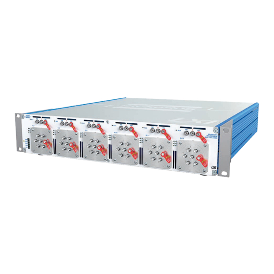
- Page 1 60-890-005 User Manual LXI 40GHz SPDT & SP6T Terminated Microwave Switch pickeringtest.com Issue 1.1 August 2020...
- Page 2 Pickering Interfaces. Technical details contained within this publication are subject to change without notice. ISO 9001 Reg No. FM38792 LXI 40GHz SPDT & SP6T TERMINATED MICROWAVE SWITCH 60-890-005 REED RELAY MODULE 40-110/115/120/125 Page (II) Page (II)
- Page 3 Pickering Interfaces strives to fulfil all relevant environmental laws and regulations and reduce wastes and releases to the environment. Pickering Interfaces aims to design and operate products in a way that protects the environment and the health and safety of its employees, customers and the public. Pickering Interfaces endeavours to develop and manufacture products that can be produced, distributed, used and recycled, or disposed of, in a safe and environmentally friendly manner.
-
Page 4: Product Safety
If this product is heavy reference should be made to the safety instructions for provisions of lifting and moving. STATIC SENSITIVE To indicate that static sensitive devices are present and handling precautions should be followed. REED RELAY MODULE 40-110/115/120/125 LXI 40GHz SPDT & SP6T TERMINATED MICROWAVE SWITCH 60-890-005 Page (IV) Page (IV) -
Page 5: Table Of Contents
LXI Status Indicators ............6.1 LAN Reset .................6.2 Section 7 Maintenance Information ............7.1 Microwave Switch Parts List ...........7.2 General Maintenance ............7.5 RF Relay Removal/Refitting ..........7.8 Appendix A Fitting Rack Mounting Flanges ..........A.1 LXI 40GHz SPDT & SP6T TERMINATED MICROWAVE SWITCH 60-890-005 Page (V) - Page 6 THIS PAGE INTENTIONALLY BLANK LXI 40GHz SPDT & SP6T TERMINATED MICROWAVE SWITCH 60-890-005 Page (VI)
-
Page 7: Warnings And Cautions
I/O signals that may be present. Blanking panels are available to order from Pickering. If the product is not used in this manner for example by using an extender card then additional care must be taken to avoid contact with exposed signals. - Page 8 CONNECTORS OR CABLE ASSEMBLIES THAT ENSURE OPERATORS WILL NOT (0.8–1.1 N·m) for stainless steel connectors. INADVERTENTLY COME IN CONTACT WITH HIGH VOLTAGES. LXI HIGH VOLTAGE 2-POLE MATRIX 60-310 Page viii LXI 40GHz SPDT & SP6T TERMINATED MICROWAVE SWITCH 60-890-005 Page (VIII)
- Page 9 Terminated SP6T Switch 2 Terminated SP6T Switch 3 Terminated SP6T Switch 4 Terminated SPDT Switch 3 Schematic Diagram for the 60-890-005 40GHz Terminated Microwave Switch - 3xSPDT & 4xSP6T pickeringtest.com LXI 40GHz SPDT & SP6T TERMINATED MICROWAVE SWITCH 60-890-005 Page 1.1...
-
Page 10: Technical Specification
Termination power rating: 1W per termination, 3W total per 6 channel multiplexer Expected Life (Low Power): 2 million operations Expected Life (Low Power): >2 million operations per position pickeringtest.com LXI 40GHz SPDT & SP6T TERMINATED MICROWAVE SWITCH 60-890-005 Page 1.2... - Page 11 -20°C to +75°C LAN Interface Humidity: Up to 90% non-condensing Compliant to LXI Standard 1.4, the 60-890-005 has a 1000Base-T Altitude: 15000m Ethernet Interface via a standard RJ-45 connector mounted on the rear panel with an LCD display showing the unit’s IP address.
- Page 12 Dual 4x4 with Loop-Thru and termination options. Mating Connectors & Cabling For connection accessories for the 60-890-005 please refer to the 90-011D RF Cable Assemblies data sheet where a complete list and documentation can be found for accessories, or refer to the Connection Solutions catalog.
- Page 13 We provide a full range of supporting cable and connector solutions for all our switching products—20 connector families with 1200+ products. We offer everything from simple mating connectors to complex cables assemblies and terminal blocks. All assemblies are manufactured by Pickering and are guaranteed to mechanically and electrically mate to our modules. Connectors & Backshells...
- Page 14 Signal Routing Software Our signal routing software, Switch Path Manager, automatically selects and energizes switch paths through Pickering switching systems. Signal routing is performed by simply defining test system endpoints to be connected together, greatly accelerating Test System software development.
-
Page 15: Technical Description
FUNCTIONAL DESCRIPTION The 60-890-005 is a microwave switch with up to 6 banks of SPDT and 6 banks of SP6T under the control of an LXI interface and is designed for the routing of signals with frequencies up to 40GHz. The individual switches can be used in isolation or cascaded to form larger switching networks. - Page 16 SECTION 2 - TECHNICAL DESCRIPTION pickering THIS PAGE INTENTIONALLY BLANK LXI 40GHz SPDT & SP6T TERMINATED MICROWAVE SWITCH 60-890-005 Page 2.2...
-
Page 17: Installation
INSTALLING THE MICROWAVE MULTIPLEXER The 60-890-005 may be mounted on a desk top or fitted into a standard 19 inch rack (rack mounting flanges are supplied with the unit that can be fitted to the sides of the front panel). When fitting into a rack it is important to... -
Page 18: Setting The Ip Address
Once you have the required information, the IP configuration window is used to manually set the IP address. This is shown in Figure 3-4. The current IP address setting of the 60-890-005 is indicated on an LCD display on the rear panel of the chassis. Figure 3-3. Display for IP Address on Rear Panel Incorrect setting will result in a loss of communication and may also be indicated by a red LAN LED on the front panel. -
Page 19: Installing The Software
SOFT FRONT PANEL OPERATION The 60-890-005 Microwave Switch can be programmed using the Soft Front Panel. This can be run as a Java Applet from the device’s LXI home page. You must have the Java Runtime environment loaded from Sun Microsystems to use this facility. - Page 20 SECTION 3 - INSTALLATION pickering THIS PAGE INTENTIONALLY BLANK LXI 40GHz SPDT & SP6T TERMINATED MICROWAVE SWITCH 60-890-005 Page 3.4...
-
Page 21: Programming Guide
SECTION 4 - PROGRAMMING GUIDE PROGRAMMING OPTIONS FOR PICKERING INTERFACES LXI UNITS For information on the installation and use of drivers and the programming of Pickering’s products in various software environments, please refer to the Software User Manual. This is available as a download from: https://www.pickeringtest.com/support/software-drivers-and-downloads... -
Page 22: Programming The Microwave Switch
PROGRAMMING THE MICROWAVE SWITCH The 60-890-005 is a mixed configuration microwave switch and can be fitted with up to six SPDT and six SP6T switches. The SPDT switches default to the Com-NC signal path with the NO connection terminated into 50Ω. When activated, the signal path is between Com-NO with the NC connection terminated into 50Ω. - Page 23 Com to 2 comL chL2 Com to 3 comL chL3 RL12 SP6T Com to 4 comL chL4 Com to 5 comL chL5 Com to 6 comL chL6 LXI 40GHz SPDT & SP6T TERMINATED MICROWAVE SWITCH 60-890-005 Page 4.3...
- Page 24 Direct I/O Driver, piplx The Direct I/O driver is composed of a suite of separate libraries which interact to provide full control of a Pickering LXI unit. In the case of a switch card the communications library picmlx, and the switching library piplx, are needed.
- Page 25 The following code snippet demonstrates the minimum steps required to operate a switch on a Pickering LXI unit. Firstly a device session is opened on the card located at bus 0, device 20 inside the LXI unit located at 192.168.1.100.
- Page 26 SECTION 4 - PROGRAMMING GUIDE pickering The implementation of a MUX switch in the Pickering driver requires explicit disconnection of a previously connected path before a new path may be selected. That is, a set of calls thus: Connect(“comG”, “chG1”);...
- Page 27 Soft Front Panel The 60-890-005 Microwave Switch can be programmed using the supplied Soft Front Panel. This can be run as a Java Applet from the devices LXI home page. An example of this is shown in Figure 4.3. For a description of the controls, refer to “Using The Soft Front Panel”...
-
Page 28: Command Line Control
LXI instrument from the Windows utility PILMon and provides identical functionality. Enabling the Command Line Control Utility Pickering LXI devices do not provide an SSH server in the normal configuration state, the service must be explicitly enabled. - Page 29 SECTION 4 - PROGRAMMING GUIDE pickering Step 2 - Enable the SSH server Select the Diagnostics page from the main menu LXI 40GHz SPDT & SP6T TERMINATED MICROWAVE SWITCH 60-890-005 Page 4.9...
- Page 30 LAN Reset button located at the rear of the device in the appropriate manner, refer to Section 7 of this manual for details of this process. Disabling security will stop the SSH service. LXI 40GHz SPDT & SP6T TERMINATED MICROWAVE SWITCH 60-890-005 Page 4.10...
- Page 31 First start up the SSH client and enter the IP address of the LXI device. The user will be prompted for a login name and password. The username for instrument control is ‘sshuser’, the password is that defined by the user when setting security. LXI 40GHz SPDT & SP6T TERMINATED MICROWAVE SWITCH 60-890-005 Page 4.11...
- Page 32 Before attempting to control a card it is important to understand the switch architecture of that card and to know how to address the required switch. Each Pickering switch card is represented as a set of one or more sub-units, each sub-unit containing one or more switches.
- Page 33 In the case of matrix sub-units, the XC and XO commands are useful, obviating the need for the user to calculate the bit position for a crosspoint in the matrix by allowing a point to be addressed by row and column address. LXI 40GHz SPDT & SP6T TERMINATED MICROWAVE SWITCH 60-890-005 Page 4.13...
- Page 34 = show PSU output voltage setting PE <0|1> = DISABLE|ENABLE the output of a PSU = show number of free cards = list bus/slot locations of free cards = quit the program LXI 40GHz SPDT & SP6T TERMINATED MICROWAVE SWITCH 60-890-005 Page 4.14...
-
Page 35: Using The Soft Front Panel
- Tabs at the top of the screen are used to select the particular relay to be controlled Figure 4-5. Once the required relay has been selected, the buttons representing a particular switching element can be clicked on to enable the corresponding signal path LXI 40GHz SPDT & SP6T TERMINATED MICROWAVE SWITCH 60-890-005 Page 4.15... - Page 36 SECTION 4 - PROGRAMMING GUIDE pickering THIS PAGE INTENTIONALLY BLANK LXI 40GHz SPDT & SP6T TERMINATED MICROWAVE SWITCH 60-890-005 Page 4.16...
-
Page 37: Connections
3-5 in·lbs (0.3 to 0.6 N·m) for brass, and 7-10 in·lbs (0.8–1.1 N·m) for stainless steel connectors. Figure 5-1. Front Panel Layout for the 60-890-005 LXI Microwave Switch Populated as 3xSPDT & 4xSP6T LXI 40GHz SPDT & SP6T TERMINATED MICROWAVE SWITCH 60-890-005 Page 5.1... - Page 38 Service Port (for Pickering diagnostics only) IP Address Display Air Outlet Air Outlet Power Switch Fuses Mains Inlet Figure 5-2. Rear Panel Layout for the 60-890-005 LXI Microwave Switch LXI 40GHz SPDT & SP6T TERMINATED MICROWAVE SWITCH 60-890-005 Page 5.2...
-
Page 39: Trouble Shooting
Refer to the Warnings and Cautions at the front of this manual INSTALLATION PROBLEMS The Plug & Play functionality of Pickering switching products generally ensures trouble-free installation. If you do experience any installation problems you should first ensure that all cables are properly connected. -
Page 40: Lan Reset
Q All of my device’s lights are on, why don’t I see a green Ready light, even after a few minutes? Your device has a fault, contact your local sales office. Please contact your local Pickering Interfaces sales office for any further support or email: Lxisupport@pickeringtest.com You can also visit our website for product updates, help and downloadable materials at: http://www.pickeringtest.com... -
Page 41: Maintenance Information
PCB. The tables can be used in the fault finding process and should be used in conjunction with the corresponding PCB layout diagrams to identify the position of faulty relays. LXI HIGH DENSITY EMR MATRIX 60-550/551 LXI 40GHz SPDT & SP6T TERMINATED MICROWAVE SWITCH 60-890-005 Page 7.1 Page 7.1... -
Page 42: Microwave Switch Parts List
MICROWAVE SWITCH PARTS LIST The 60-890-005 LXI Microwave Switch chassis can be fitted with up to 6xSPDT and 6xSP6T microwave relays and contains 2 Relay Driver PCBs as well as 2 Power Supplies and a Microcontroller assembly. The following pages provide a parts list and internal layout for the PCBs and sub-assemblies that make up the LXI Microwave Switch. - Page 43 Ribbon Cable: LXI Status LED Board to 16-pin C-CN-991 Microcontroller Board Cooling Fan Assembly 12V DC, 60mm, C-MS-630 Aerco 15mm thick AD0612HB-D73GL Cooling Fan Controller Board PCB 619 A-PC-619 LXI 40GHz SPDT & SP6T TERMINATED MICROWAVE SWITCH 60-890-005 Page 7.3...
- Page 44 SP6T Switch Switch (RL5) (RL11) Power Supply “PSU 1” SPDT SP6T Switch Switch (RL6) (RL12) Figure 7-2. 60-890-005 LXI Microwave Switch - 3xSPDT and 4xSP6T Version Internal Module Layout LXI 40GHz SPDT & SP6T TERMINATED MICROWAVE SWITCH 60-890-005 Page 7.4...
-
Page 45: General Maintenance
Driver Board 1 via a ribbon cable. Up to four relay driver boards can be fitted to the 60-890-005, with the second and subsequent boards receiving their serial data from the first board in a daisy-chain configuration. - Page 46 Ribbon cables transfer switching signals to the interface PCBs from the relay driver boards. A maximum of six SP6T relays can be fitted to the 60-890-005. The microwave relay assemblies are fitted through apertures in the front panel allowing them to be replaced without removing the chassis covers or removing the chassis from the host rack.
- Page 47 Cables (3off) Switch (C-CN-1195) (C-CN-1430) With Fuse Drawer (C-CN-1196) RL12 SP6T Relay Assy 60-890-005 CHASSIS Mains Power Input Figure 7-3. 60-890-005 LXI Microwave Swotch - Internal Wiring (Fully Populated) LXI 40GHz SPDT & SP6T TERMINATED MICROWAVE SWITCH 60-890-005 Page 7.7...
-
Page 48: Rf Relay Removal/Refitting
RF RELAY REMOVAL/REFITTING The SP6T relays of the 60-890-005 are replaceable units, in case of failure, they can easily be changed by the user. The relays are removed from the front panel without opening the chassis covers or removing the chassis from its rack installation. - Page 49 6. The unit is now ready to have a new relay module fitted. LXI 40GHz SPDT & SP6T TERMINATED MICROWAVE SWITCH 60-890-005 Page 7.9...
- Page 50 10. Finally, re-connect any RF cabling that was removed in step 1. The chassis can now be powered up and the new relay is ready for use. LXI 40GHz SPDT & SP6T TERMINATED MICROWAVE SWITCH 60-890-005 Page 7.10...
-
Page 51: Fitting Rack Mounting Flanges
APPENDIX A - FITTING RACK MOUNTING FLANGES Pickering’s LXI devices are supplied with mounting flanges to enable fitting into a standard 19 inch rack. The following procedure describes the attachment of the flanges to the unit’s side extrusions, a No.1 cross head screwdriver will be required. - Page 52 APPENDIX A - FITTING RACK MOUNTING FLANGES pickering THIS PAGE INTENTIONALLY BLANK LXI 40GHz SPDT & SP6T TERMINATED MICROWAVE SWITCH 60-890-005 Page A.2...
Need help?
Do you have a question about the 60-890-005 and is the answer not in the manual?
Questions and answers