
Related Manuals for Pickering SIM SIMRC-1000 Series


Summary of Contents for Pickering SIM SIMRC-1000 Series
- Page 1 SIMRC-1000 Series User Manual SIM Switch Cards & Accessories pickeringtest.com Issue 5.0 September 2023...
- Page 2 © COPYRIGHT (2023) PICKERING INTERFACES. ALL RIGHTS RESERVED. No part of this publication may be reproduced, transmitted, transcribed, translated or stored in any form, or by any means without the written permission of Pickering Interfaces. Technical details contained within this publication are subject to change without notice.
- Page 3 Pickering Interfaces strives to fulfil all relevant environmental laws and regulations and reduce wastes and releases to the environment. Pickering Interfaces aims to design and operate products in a way that protects the environment and the health and safety of its employees, customers and the public. Pickering Interfaces endeavours to develop and manufacture products that can be produced, distributed, used and recycled, or disposed of, in a safe and environmentally friendly manner.
- Page 4 THIS PAGE INTENTIONALLY BLANK SIM REED RELAY CARDS SIMRC 1000 Page iv...
-
Page 5: Table Of Contents
CONTENTS Copyright Statement ............ii Technical Support and Warranty ........iii Contents (this page) ............v Section 1 Introduction ................. 1.1 Series 1010 Reed Relay Configurations ....1.2 Series 1020 Multiplexer Configurations ....1.2 Series 1030 Matrix Configurations ......1.2 Accessories (Carrier Cards and Control Interfaces) .. 1.3 Section 2 Technical Specification ............ - Page 6 THIS PAGE INTENTIONALLY BLANK SIM REED RELAY CARDS SIMRC 1000 Page vi...
-
Page 7: Introduction
SECTION 1 - INTRODUCTION Pickering Interfaces Series 1000 SIM Reed Relay Cards offer a choice of switching configurations using low cost industry standard SIM connectors. They free the designer from the detail of routing complex switching circuits, you may select from a wide range of cards using the built in RS-232 and I C interfaces. -
Page 8: Series 1010 Reed Relay Configurations
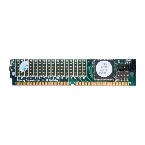
SECTION 1 - INTRODUCTION pickering Series 1010 Reed Relay Configurations 16 x SPST 16 x SPST Coax 16 x SPDT (Changeover) C/RS-232 Reed Relay SIM Card (Top View) C/RS-232 Reed Relay SIM Card (Underside View) Series 1020 Multiplexer Configurations 16.1 16.2 S 16 16-Channel 1-Pole 16-Channel 2-Pole 16-Channel 1-Pole Coax Series 1030 Matrix Configurations Matrix 1-Pole Matrix 2-Pole 8 x 4 Matrix 1-Pole Coax... -
Page 9: Accessories (Carrier Cards And Control Interfaces)
SECTION 1 - INTRODUCTION pickering Accessories (Carrier Cards and Control Interfaces) Carrier cards are available that support either one or three SIM cards. For applications where more than one SIM relay card is supported, each card can be I C controlled and an optional RS232 to I converter used to provide overall RS232 control. - Page 10 SECTION 1 - INTRODUCTION pickering THIS PAGE INTENTIONALLY BLANK Page 1.4 SIM REED RELAY CARDS SIMRC 1000...
- Page 11 Care must be taken with the motherboard Required Voltage: 5V ±0.25V layout to ensure good RF performance (for example correct track dimensions and good ground planes), please contact Pickering for Current: 100mA typical per SIM further assistance. Versions suitable for RF use have “RF” in their <200mA with 8 relays selected...
- Page 12 SECTION 2 - SPECIFICATION pickering Ordering Information SIM Reed Relay Cards, SIMRC 1000 Product Order Codes Series 1010 - Uncommitted Reed Relay Cards 16 x SPST Reed Relays 1010-R-16-1-5/1D 16 x SPDT Reed Relays 1010-R-16-1-5/3D 16 x SPST Screened Reed Relays...
-
Page 13: Rf Specification For Rf Versions
Ω Ω the 72 way edge connector. Care must be taken with the motherboard layout to ensure good RF performance (for example correct track dimensions and good ground planes), please contact Pickering for further assistance. SPST ISOLATION SPST INSERTION LOSS... - Page 14 SECTION 2 - SPECIFICATION pickering THIS PAGE INTENTIONALLY BLANK SIM REED RELAY CARDS SIMRC 1000 Page 2.4...
-
Page 15: Installation And Operation
SECTION 3 - INSTALLATION AND OPERATION pickering SECTION 3 - INSTALLATION & OPERATION WARNING - DANGER OF ELECTRIC SHOCK BEFORE REMOVING THE MODULE FROM THE MOTHER BOARD ENSURE THAT ALL CONNECTIONS TO THE MODULE ARE REMOVED CAUTION Electrostatic discharge can damage the components on the module. To avoid such damage in handling the board, touch the anti-static bag to a metal part of the chassis before removing the board from the bag. - Page 16 SECTION 3 - INSTALLATION AND OPERATION pickering Constructing Large Switching Networks with RS-232 or I The SIM Relay Card may be operated by RS-232 or I C in the ways shown in the diagrams below. For a description and wiring diagram for interconnecting multiple SIMRC modules in a daisy-chain configuration, please refer to Section 6.
-
Page 17: Programming
= Syntax error, unrecognised command etc. = Bad command delimiter = Bad hexadecimal = Bad decimal = Value out of range = Trailing garbage For further information on the command set please contact Pickering Interfaces. Page 4.1 SIM REED RELAY CARDS SIMRC 1000... -
Page 18: Command Execution Timings
SECTION 4 - PROGRAMMING pickering Command Execution Timings The graph below gives typical execution times for operating single relays and blocks of relays using both the I C and RS-232 bus. (100kbit) Communication Time Processing Time Relay Settling Time Close 1... -
Page 19: I 2 C Bus Operation
SECTION 4 - PROGRAMMING pickering C-bus Operation The protocol for I C-bus operation is modelled on IEEE488.2, which is a well-proven and reliable standard. The use of command and query mnemonics, and the facility for obtaining extended response data from the unit are features intended to allow it’s use in more complex devices. - Page 20 SECTION 4 - PROGRAMMING pickering The number of data bytes required by the SB command depends on the number of outputs available on the particular module: a 32-output module requires 4 bytes, a 16-output module requires 2 bytes. Data bytes received are interpreted in descending order of significance;...
-
Page 21: Rs232 Operation
SECTION 4 - PROGRAMMING pickering RS-232 Operation Communication Standard and Handshaking Communication settings are fixed at 9600 baud, 8N1. Neither hardware (CTS/RTS) nor software (XON/XOFF) handshaking is employed bySIMRCs. Data input is line buffered, full duplex, supporting backspace-and-delete. Input line terminator is <CR>; output lines are terminated with <CR + LF>. - Page 22 SECTION 4 - PROGRAMMING pickering TY query: Module identification string, eg. “SW160001” “SW” = module type “16” = module dimension (X) “00” = module dimension (Y), or special features code “01” = firmware release number WH query: Module introductory message, including firmware revision and I C address setting.
- Page 23 SECTION 4 - PROGRAMMING pickering Programming examples A good way to become familiar with operation is to use a serial terminal or Terminal Emulator program (such as Windows HyperTerminal) to communicate with a unit via it’s RS-232 port. 16-channel switch module - get type info (typical response “SW160001”)
-
Page 24: 1080 Sim Relay Card Controller
C-bus operations and can be used for communication with any I C device. A further set of commands are specific to Pickering SIM Relay Cards. RS-232 operation is fixed at 9600 baud, 8N1; neither hardware (eg. CTS/RTS) or software (XON/XOFF) handshaking is supported. - Page 25 SECTION 4 - PROGRAMMING pickering Error Messages Error messages consist of the “?” character, followed by a code letter indicating the nature of the error:- = Address Unset - no slave address has been set = Syntax error = Trailing garbage...
- Page 26 SECTION 4 - PROGRAMMING pickering Typical SIMRC operating times Single switch operation: 25ms approx. Programmatic Operation All commands related to I C-bus activity generate a single-line response (either “OK” or a data value, or an error message). The converter can therefore be operated programmatically using the following handshake protocol:...
-
Page 27: Connector Pin Outs
SECTION 5 - PIN OUTS pickering SECTION 5 - CONNECTOR PIN OUTS Figure 5.1 provides the connector positioning for the SIMRC1010/1020 relay/multiplexer SIM card Figure 5.2 shows the connector positioning for the SIMRC1030 matrix SIM card. RS232/I LOCATION CONNECTOR HOLE... - Page 28 SECTION 5 - PIN OUTS pickering GREEN RS232/I ADDRESS STATUS LOCATION CONNECTOR JUMPERS HOLE INTERFACE SELECTION JUMPERS ADDRESS SWITCH POWER LOCATION PIN 1 HOLE CUT-OUT Figure 5.2 - SIMRC 1030 Connector Positions Page 5.2 SIM REED RELAY CARDS SIMRC 1000...
-
Page 29: I 2 C/Rs232 Connector
SECTION 5 - PIN OUTS pickering C/RS232 Connector The SIM Relay Card has a configurable I C/RS-232 port (9600 baud, 8 bit, no parity, no handshaking). This is provided on a 4 pin Molex type connector as shown in Figure 5.3. (a jumper on the PCB selects RS-232 or I C use for this port see Figure 5.4). -
Page 30: Pinout Connections For All Simrc Cards
SECTION 5 - PIN OUTS pickering Pinout Connections For All SIMRC Cards Page 5.4 SIM REED RELAY CARDS SIMRC 1000... -
Page 31: General Description
72-pin gold plated SIM edge connector • PIC 8-Bit RISC Microcontroller • Relay drivers • 16 Pickering Reed Relays (32 for the 1030 Matrix card) • 4-pin Molex Datamate plug for I C or RS232 control • 4-way DIP switch and 3-way jumper for I C address configuration •... -
Page 32: Daisy Chaining Modules
SECTION 6 - GENERAL DESCRIPTION pickering Daisy-Chaining Modules The I C ports of the SIMRC modules can be daisy-chained together to allow multiple cards to be programmed by one host controller. To do this the cards should be set with different addresses and the 72-pin connector wired as shown in Figure 6.2. -
Page 33: Carrier Cards
Single SIM Small Outline Carrier Card Pickering Interfaces have produced a small PCB to allow users to work with SIMRC cards - product code 1091-001. It comprises a SIM Socket fitted to a PCB with terminals suitable for solder connection. Two holes are provided for mounting the PCB, as shown in Figure 6.3. - Page 34 SIM Relay Card Carrier SIMRC-1050 SECTION 6 - GENERAL DESCRIPTION pickering 1050 SIMRC Carrier Card y Easy Integration of SIMRC Cards for Custom Applications y Utilizes SIMRC Cards From The Series 1010/1020/1030 y RS-232 Interface y Standard Subminiature 50-pin and 9-pin D-type Connectors...
- Page 35 SECTION 6 - GENERAL DESCRIPTION pickering Specifications & Ordering Information SIM Reed Relay Card Carrier, 1050 Power Supply Specification Product Order Codes +5V DC, protected with a 1.25A fuse (TR5 type). SIM Relay Card Carrier PCB 1050-001 Current consumption (no SIMRC Modules, only 1080-001 Including mating connectors 3xmale 50-pin installed): Typically 25mA.
- Page 36 SECTION 6 - GENERAL DESCRIPTION Overview pickering SIM Reed Relay Card Carrier, 1050 Pin Connections Between The SIM Relay Card And 50-pin D-Type Connector X1.1 X1.1 — — — X1.2 — X1.2 X2.1 X2.1 — — X2.2 — X2.2 —...
- Page 37 SECTION 6 - GENERAL DESCRIPTION pickering Specifications SIM Reed Relay Card Carrier, 1050 Dimensions Of The SIM Relay Card Carrier CASCADE External 5V DC to be applied to J10-2(+) (J10-1(-) is GND) RS232 J10-2(+) 1.25A 820R J10-1(-) 1N5402 Schematic Diagram Of The Serial Data And Power Connections Of The SIM Relay Card Carrier pickeringtest.com...
- Page 38 SECTION 6 - GENERAL DESCRIPTION pickering SIM Relay Card Carrier Parts List Page 6.8 SIM REED RELAY CARDS SIMRC 1000...
-
Page 39: Support Products
SIM Relay Card or Converter Module to a standard 9-pin D-type suitable for connecting to a host PC 72-Pin SIM Connector Also Pickering can provide a standard 72-pin SIM connector for the user to fit to their own motherboard as shown in Figure 6.12. (model number 1090-001). - Page 40 SECTION 6 - GENERAL DESCRIPTION pickering THIS PAGE INTENTIONALLY BLANK Page 6.10 SIM REED RELAY CARDS SIMRC 1000...
-
Page 41: Warnings And Cautions
SECTION 7 - WARNINGS AND CAUTIONS WARNING – HAZARDOUS ENVIRONMENTS This product is not specifically designed for use in hazardous environments, for example in explosive atmospheres. If the product is to be used in hazardous environments we recommend that the user ensures suitable protective measures are taken. - Page 42 THIS PAGE INTENTIONALLY BLANK Page 7.2 SIM REED RELAY CARDS SIMRC 1000...
Need help?
Do you have a question about the SIM SIMRC-1000 Series and is the answer not in the manual?
Questions and answers