
Related Manuals for Pickering LXI 60-102C


Summary of Contents for Pickering LXI 60-102C
- Page 1 60-102C User Manual LXI 7-Slot Modular Switching Chassis pickeringtest.com Issue 1.1 January 2023...
- Page 2 © COPYRIGHT (2023) PICKERING INTERFACES. ALL RIGHTS RESERVED. No part of this publication may be reproduced, transmitted, transcribed, translated or stored in any form, or by any means without the written permission of Pickering Interfaces. Technical details contained within this publication are subject to change without notice.
- Page 3 Pickering Interfaces strives to fulfil all relevant environmental laws and regulations and reduce wastes and releases to the environment. Pickering Interfaces aims to design and operate products in a way that protects the environment and the health and safety of its employees, customers and the public. Pickering Interfaces endeavours to develop and manufacture products that can be produced, distributed, used and recycled, or disposed of, in a safe and environmentally friendly manner.
-
Page 4: Product Safety
PRODUCT SAFETY SAFETY SYMBOLS The following safety symbols may be used on the product and throughout the product documentation. MEANING / DESCRIPTION SYMBOL PROTECTIVE EARTH (GROUND) To identify any terminal which is intended for connection to an external conductor for protection against electric shock in case of a fault, or the terminal of a protective earth (ground) electrode. -
Page 5: Table Of Contents
CONTENTS Copyright Statement ..............II Technical Support and Warranty ..........III Product Safety ................IV Contents (this page) ..............V Warnings and Cautions ..............VII Section 1 Technical Specification ...............1.1 Section 2 Technical Description ..............2.1 Mechanical Description ............2.1 Functional Description ............2.2 PXI Module Support ..............2.3 Section 3 Installation ..................3.1... - Page 6 THIS PAGE INTENTIONALLY BLANK LXI 7-SLOT MODULAR SWITCHING CHASSIS 60-102C Page (VI)
-
Page 7: Warnings And Cautions
Unused slots in this chassis are populated with blanking panels to prevent access to user I/O signals that may be present. Blanking panels are available to order from Pickering. If the product is not used in this manner for example by using an extender card then additional care must be taken to avoid contact with exposed signals. - Page 8 CAUTION - PRODUCT DOCUMENTATION SYMBOL Suitably qualified & trained users should ensure that the accompanying documentation is fully read and understood before attempting to install or operate the product. SAFETY INSTRUCTIONS SAFETY INSTRUCTIONS All cleaning and servicing requires the equipment to be isolated and disconnected from the power source and user I/O signals (refer to the Maintenance Section).
- Page 9 The controller. separation of the chassis from the controller’s PCI bus simplifies † For compatibility of Pickering’s PXI modules other than system power-on sequencing and provides independence from the switching or simulation functions, please check the module’s data migration of the Windows and VISA environment.
-
Page 10: Technical Specification
SECTION 1 - TECHNICAL SPECIFICATION pickering Overview LXI 7-Slot Modular Chassis, 60-102C The home page for the 60-102C provides fast access to configuration information for the LXI chassis through any web browser. The 60-102C provides soft front panels to enable manual operation through the web interface, in this example for a 40-513 matrix module. - Page 11 Sound Power (dBA): Minimum fan speed: 51.9 dB PXI Module compatibility Maximum fan speed 55.5 dB The chassis is supplied with drivers for Pickering system 40 switching modules. Monitoring Switching Support: All of 3U Pickering LXI Interface Status LEDs: Power, Ready, Error, LAN, Interface’s PXI switching...
- Page 12 SECTION 1 - TECHNICAL SPECIFICATION Specifications & Ordering Information pickering LXI 7-Slot Modular Chassis, 60-102C Operating/Storage Conditions Product Order Codes Operating Conditions LXI Modular Chassis, 7-Slot 60-102C-001 Operating Temperature: 0 °C to +55 °C Optional 19” rack mounting hardware* 63-924-001...
- Page 13 To learn more, please go to: pickeringrelay.com Programming Pickering provide kernel, IVI and VISA (NI & Keysight) drivers which are compatible with all Microsoft supported versions of Windows and popular older versions. For a list of all supporting operating systems, please see: pickeringtest.com/os The VISA driver support is provided for LabVIEW Real Time Operating Systems (Pharlap and Linux-RT).
- Page 14 Three Year Warranty & Guaranteed Long-Term Support All standard products manufactured by Pickering Interfaces are warranted against defective materials and workmanship for a period of three years from the date of delivery to the original purchaser. Extended warranty and service agreements are available for all our modules and systems with various levels to suit your requirements.
-
Page 15: Technical Description
SECTION 2 - TECHNICAL DESCRIPTION pickering SECTION 2 - TECHNICAL DESCRIPTION MECHANICAL DESCRIPTION The 60-102C LXI Chassis comprises the following: • Half width rack chassis suitable for desk top operation. • 7 slot PXI/cPCI compatible backplane. • Controller module for providing the interface between the backplane and the Ethernet port. -
Page 16: Functional Description
Ethernet address. Programming documentation for the chassis as well as data for Pickering’s LXI compatible switching products is stored in the embedded processor on the controller card and can be downloaded over the LAN interface. LXI Status LEDs on the front of the chassis indicate condition of the LAN interface. -
Page 17: Pxi Module Support
PXI MODULE SUPPORT The 60-102C supports a wide variety of Pickering Interfaces 3U PXI modules, the backplane of the chassis is conformant to the PXI standard. The chassis LXI interface is conformant with the stated version of the LXI standard. - Page 18 SECTION 2 - TECHNICAL DESCRIPTION pickering THIS PAGE INTENTIONALLY BLANK LXI 7-SLOT MODULAR SWITCHING CHASSIS 60-102C Page 2.4...
-
Page 19: Installation
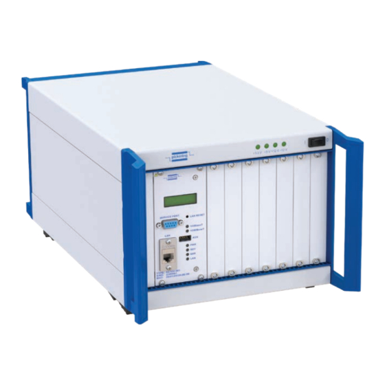
5U of rack space and must have its bottom feet inplace to ensure the correct flow of cooling air. Also it can be installed in a rack using Pickering’s rack mounting hardware 63-924-001. Figure 3.1 - Front of the 60-102C LXI Chassis LXI 7-SLOT MODULAR SWITCHING CHASSIS 60-102C Page 3.1... - Page 20 SECTION 3 - INSTALLATION pickering Cooling Considerations The chassis draws cooling air for the PXI modules through an intake in the underside of the chassis directly below the PXI slots (see Figure 3.2). It is important not to block the passage of air into this intake.
- Page 21 Switch +3.3V +5V +12V +12V IP Address Display Reset Button SERVICE PORT Service Port LAN RESET (Pickering diagnostics only) 100BaseT LAN Speed Indicators 1000BaseT Ethernet Port LXI Status Indicators LXI Control Module PXI Module Slots Figure 3.3 - Front of the 60-102C LXI Chassis showing PXI slots,...
-
Page 22: Installation Of Individual Modules
SECTION 3 - INSTALLATION pickering Rack Mounting The Chassis The 60-102C can be fitted into a standard 19 inch equipment rack using the optional 63-924-001 Mounting Kit. The kit consists of a frame into which the chassis is mounted that increases the overall height to 5U and allows space for cooling air to be drawn into the underside of the chassis. -
Page 23: Setting The Ip Address
SECTION 4 - CONFIGURATION & SET-UP pickering SECTION 4 - CONFIGURATION & SET-UP SETTING THE IP ADDRESS To use the 60-102C LXI Modular Switching Chassis over a LAN connection it should be set up and configured as described in the “LXI Getting Started Guide” document. - Page 24 SECTION 4 - CONFIGURATION & SET-UP pickering THIS PAGE INTENTIONALLY BLANK LXI 7-SLOT MODULAR SWITCHING CHASSIS 60-102C Page 4.6...
-
Page 25: Programming
SECTION 5 - PROGRAMMING GUIDE Programming options for Pickering Interfaces LXI Units For information on the installation and use of drivers and the programming of Pickering’s products in various software environments, please refer to the Software User Manual. This is available as a download from: https://www.pickeringtest.com/support/software-drivers-and-downloads... -
Page 26: Unit Architecture
It is vital to know that location in order to specify the address of the switch to be controlled. Pickering provide software tools to help you discover the bus and device number of the cards in your LXI unit. Refer to the distribution disk that came with your unit in the folder LXI Products/Tools. - Page 27 0, device 20. For full details of how to access and use Pickering drivers the user is advised to refer to the individual documentation packs provided with the installed drivers, this can be found on the distribution disk that came with your unit.
-
Page 28: Command Line Control Of Lxi Instruments
LXI instrument from the Windows utility PILMon and provides identical functionality. Enabling the Command Line Control Utility Pickering LXI devices do not provide an SSH server in the normal configuration state, the service must be explicitly enabled. - Page 29 SECTION 5 - PROGRAMMING GUIDE pickering Step 2 - Enable the SSH server Select Instrument Control from the main menu NOTES: The password and state of the SSH server are stored in non-volatile memory within the LXI device and so will remain in effect even after a power cycle.
- Page 30 SECTION 5 - PROGRAMMING GUIDE pickering Instrument Control from an SSH Client In the following examples the SSH client PuTTY is used, the user will have to adapt the instructions for any other client. First start up the SSH client and enter the IP address of the LXI device. The user will be prompted for a login name and password.
- Page 31 Before attempting to control a card it is important to understand the switch architecture of that card and to know how to address the required switch. Each Pickering switch card is represented as a set of one or more sub-units, each sub-unit containing one or more switches.
- Page 32 SECTION 5 - PROGRAMMING GUIDE pickering <no parameters> Close selected card. Card cannot be used until opened CardClose again. CardCloseAll CLA <no parameters> Close all opened cards. <no parameters> Get text diagnostic of selected card. When card is faulty CardDiagnostic diagnostics shows details about faults.
- Page 33 SECTION 5 - PROGRAMMING GUIDE pickering <bit(int)> Get state of mask of switch on selected subunit of index <bit>. SwitchMaskView Returns 1 if mask is active 0 otherwise. <no parameters> Clear all switches (set relays to their default state) on SubunitClear selected subunit.
- Page 34 SECTION 5 - PROGRAMMING GUIDE pickering <column(int)> <row(int)> Get state of mask of switch on selected matrix subu- XpointMaskView nit in position <column> <row>. Returns 1 if mask is active 0 otherwise. Set driver in different working mode. This feature is to be used only by...
- Page 35 SECTION 5 - PROGRAMMING GUIDE pickering So a quick example to operate a bit on the card would be: COA > open all cards LS > list the cards USL 1 1 > Select the card 1 and sub-unit 1 SC 1 >...
- Page 36 SECTION 5 - PROGRAMMING GUIDE pickering THIS PAGE INTENTIONALLY BLANK LXI 7-SLOT MODULAR SWITCHING CHASSIS 60-102C Page 5.12...
-
Page 37: Trouble Shooting
SECTION 6 - TROUBLE SHOOTING pickering SECTION 6 - TROUBLE SHOOTING Refer to the Warnings and Cautions at the front of this manual LXI STATUS INDICATORS Status Indicator / Colour Status Description Powering Up Status: This state occurs when the LXI unit was turned off and the user turns it on. - Page 38 1 minute. So if the bootup takes too long or you still cannot see RDY and LAN lights on after a few minutes, please contact your local sales office, because this means the sofware or hardware are faulty. Please contact your local Pickering Interfaces sales office for any further support or email: Lxisupport@pickeringtest.com You can also visit our website for product updates, help and downloadable materials at: http://www.pickeringtest.com...
-
Page 39: Unit Reset
SECTION 6 - TROUBLE SHOOTING pickering UNIT RESET If the chassis operation is inconsistent, the user should try to power cycle the chassis using the standard power button located on the front of the unit or power cycle the chassis from the web interface. - Page 40 SECTION 6 - TROUBLE SHOOTING pickering THIS PAGE INTENTIONALLY BLANK LXI 7-SLOT MODULAR SWITCHING CHASSIS 60-102C Page 6.4...
-
Page 41: Rack Mounting The Chassis
APPENDIX A - RACK MOUNTING pickering APPENDIX A - RACK MOUNTING THE CHASSIS To allow the 60-102C chassis to be fitted in a 19 inch equipment rack it can be simply mounted on a standard equipment shelf, or preferably, it can be fitted with the 63-924-001 rack mounting kit. The kit allows the chassis to be securely fixed in a rack with top and bottom spacing to provide the correct flow of cooling air. - Page 42 APPENDIX A - RACK MOUNTING pickering 4. Place the two chassis mounting rails on the underside of the chassis as shown. Align the two fixing holes in each rail with the threaded holes used for the plastic feet and secure with the fixing screws.
Need help?
Do you have a question about the LXI 60-102C and is the answer not in the manual?
Questions and answers