
Related Manuals for Pickering LXI 60-890-022


Summary of Contents for Pickering LXI 60-890-022
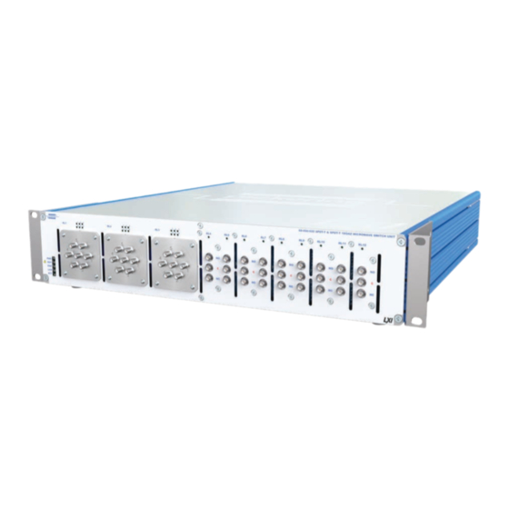
- Page 1 60-890-022 User Manual LXI 18 GHz Custom Microwave Unit pickeringtest.com Issue 1.0 October 2022...
- Page 2 © COPYRIGHT (2022) PICKERING INTERFACES. ALL RIGHTS RESERVED. No part of this publication may be reproduced, transmitted, transcribed, translated or stored in any form, or by any means without the written permission of Pickering Interfaces. Technical details contained within this publication are subject to change without notice.
- Page 3 Pickering Interfaces strives to fulfil all relevant environmental laws and regulations and reduce wastes and releases to the environment. Pickering Interfaces aims to design and operate products in a way that protects the environment and the health and safety of its employees, customers and the public. Pickering Interfaces endeavours to develop and manufacture products that can be produced, distributed, used and recycled, or disposed of, in a safe and environmentally friendly manner.
-
Page 4: Product Safety
PRODUCT SAFETY SAFETY SYMBOLS The following safety symbols may be used on the product and throughout the product documentation. MEANING / DESCRIPTION SYMBOL PROTECTIVE EARTH (GROUND) To identify any terminal which is intended for connection to an external conductor for protection against electric shock in case of a fault, or the terminal of a protective earth (ground) electrode. -
Page 5: Table Of Contents
CONTENTS Copyright Statement ..............II Technical Support and Warranty ..........III Product Safety ................IV Contents (this page) ..............V Warnings and Cautions .............. VII Section 1 Technical Specification ...............1.1 Section 2 Technical Description ..............2.1 Functional Description ............2.1 Section 3 Installation ..................3.1 Pre Operation Checks .............3.1... - Page 6 THIS PAGE INTENTIONALLY BLANK LXI 18 GHz CUSTOM MICROWAVE UNIT 60-890-022 Page (VI)
-
Page 7: Warnings And Cautions
I/O signals that may be present. Blanking panels are available to order from Pickering. If the product is not used in this manner for example by using an extender card then additional care must be taken to avoid contact with exposed signals. - Page 8 CAUTION - PRODUCT DOCUMENTATION SYMBOL Suitably qualified & trained users should ensure that the accompanying documentation is fully read and understood before attempting to install or operate the product. SAFETY INSTRUCTIONS SAFETY INSTRUCTIONS All cleaning and servicing requires the equipment to be isolated and disconnected from the power source and user I/O signals (refer to the Maintenance Section).
-
Page 9: Technical Specification
Other Microwave Switching Configurations We are able to offer other microwave switching solutions, if you have a custom requirement for switching please contact your local Pickering 9x Terminated SPDT Switches Interfaces sales representative. Switching Diagram for the 60-890-022 Custom Microwave Unit Issue 1.0 October 2022... - Page 10 SECTION 1 - TECHNICAL SPECIFICATION pickering Specifications 60-890-022 General Unit Information Specifications – 18 GHz SP6T Terminated Switch Configuration: Three SP6T terminated Operating Frequency: 0 - 18 GHz microwave switches and Characteristic Impedance: 50 Ω nine SPDT terminated Connectors: microwave switches Insertion Loss: <0.2 dB to 3 GHz...
- Page 11 SECTION 1 - TECHNICAL SPECIFICATION pickering Specifications 60-890-022 Mechanical Characteristics LXI Status Indicators 2 U high, full 19” rack width, 500mm deep. Front panel mounted LEDs: • Power Supplied with front panel ears to enable rack mounting on a shelf or other rear support mechanism.
- Page 12 Triple SP6T Terminated & Nonuple SPDT Terminated: 60-890-022 Product Customization Pickering LXI units are designed and manufactured on our own flexible manufacturing lines, giving complete product 60-891-001 LXI 36:1 Microwave Multiplexer. Available With SMA Connectors (18 GHz) or BNC Con- control and enabling simple customization to meet very nectors (4 GHz).
- Page 13 1200+ products. We offer everything from simple mating connectors to complex cables assemblies and terminal blocks. All assemblies are manufactured by Pickering and are guaranteed to mechanically and electrically mate to our modules. These accessories are detailed in Connector Accessories data sheets, where a complete list and documentation can be found for each accessory.
- Page 14 Supporting Products & Software 60-890-022 Programming Pickering provide kernel, IVI and VISA (NI & Keysight) drivers which are compatible with all Microsoft supported versions of Windows and popular older versions. For more information go to pickeringtest.com/os The VISA driver is also compatible with Real-Time Operating Systems such as LabVIEW RT. For other RTOS support contact Pickering.
- Page 15 To view, download or request any of our product resources go to pickeringtest.com/resources © Copyright (2022) Pickering Interfaces. All Rights Reserved. Pickering Interfaces maintains a commitment to continuous product development, consequently we reserve the right to vary from the description given in this data sheet. pickeringtest.com Page 7 LXI 18 GHz CUSTOM MICROWAVE UNIT 60-890-022 Page 1.7...
- Page 16 SECTION 1 - TECHNICAL SPECIFICATION pickering THIS PAGE INTENTIONALLY BLANK LXI 18 GHz CUSTOM MICROWAVE UNIT 60-890-022 Page 1.8...
-
Page 17: Technical Description
Ethernet address. Programming documentation for the unit as well as data for Pickering’s other LXI compatible switching products is stored in the embedded processor and can be downloaded over the LAN interface. LXI Status LEDs on the front of the chassis indicate the condition of the unit... - Page 18 SECTION 2 - TECHNICAL DESCRIPTION pickering THIS PAGE INTENTIONALLY BLANK LXI 18 GHz CUSTOM MICROWAVE UNIT 60-890-022 Page 2.2...
-
Page 19: Installation
The product is designed for indoor use only. PREOPERATION CHECKS (UNPACKING) 1. Check the module for transport damage and report any damage immediately to Pickering Interfaces. Do not attempt to install the product if any damage is evident. 2. Ensure that the designated area for the product is of a flat and solid construction to support its weight. -
Page 20: Setting The Ip Address
SECTION 3 - INSTALLATION pickering Figure 3-2. Rear view of the Custom Microwave Unit showing the mains supply connection, LAN socket and cooling air outlets SETTING THE IP ADDRESS To use the 60-890-022 Microwave Switch over a LAN connection it should be set up and configured as described in the “LXI Getting Started Guide”... -
Page 21: Installing The Software
SECTION 3 - INSTALLATION pickering Figure 3-4. Example configuration window used to manually set the IP address of a Pickering LXI device INSTALLING THE SOFTWARE From the device web page, select ‘Driver Download’ from the menu at the left of the page. This will retrieve the driver from the instrument and install it on your PC. - Page 22 SECTION 3 - INSTALLATION pickering THIS PAGE INTENTIONALLY BLANK LXI 18 GHz CUSTOM MICROWAVE UNIT 60-890-022 Page 3.4...
-
Page 23: Programming Guide
SECTION 4 - PROGRAMMING GUIDE PROGRAMMING OPTIONS FOR PICKERING INTERFACES LXI UNITS For information on the installation and use of drivers and the programming of Pickering’s products in various software environments, please refer to the Software User Manual. This is available as a download from: https://www.pickeringtest.com/support/software-drivers-and-downloads... -
Page 24: Programming The Microwave Unit
SECTION 4 - PROGRAMMING GUIDE pickering PROGRAMMING THE MICROWAVE UNIT The 60-890-022 is a custom microwave unit constructed from three 6-channel terminated microwave switches and nine SPDT terminated switches. Signals paths on the SP6T switches can be set between the common terminal and any one of the 6 positions or to no connection, where on the SPDT switches can be set between the common terminal and NO position or to NC position. - Page 25 SECTION 4 - PROGRAMMING GUIDE pickering Table 4-1. 60-890-022 LXI Microwave Switch - Sub-unit/Bit Allocation Switch Switch Signal Path Signal Path Sub-unit Type (relay energized) (relay de-energized) RL1 C to 1 RL1 Open RL1 C to 2 RL1 Open RL1 C to 3...
- Page 26 Direct I/O Driver, piplx The Direct I/O driver is composed of a suite of separate libraries which interact to provide full control of a Pickering LXI unit. In the case of a switch card the communications library picmlx, and the switching library piplx, are needed.
- Page 27 Disconnect function. The following code snippet demonstrates the minimum steps required to operate a switch on a Pickering LXI unit. Firstly a device session is opened on the card located at bus 0, device 20 inside the LXI unit located at 192.168.1.100.
- Page 28 Figure 4-2. 60-890-022 LXI Microwave Unit - IVI Architecture Showing Channel Names (default switch positions shown) The implementation of a MUX switch (comA to comC) in the Pickering driver requires explicit disconnection of a previously connected path before a new path may be selected.
- Page 29 SSH (Secure SHell) Interface Refer to the section “Command Line Control of Pickering LXI Instruments” on the following pages for details of how to open this interface and general information on the command set available. After opening an SSH session the 60-890-022 is controlled as follows: To select a multiplexer sub-unit on the LXI unit (card 1), type AD followed by the card number and sub-unit number eg: AD 1 2 (this will select multiplexer bank 2).
-
Page 30: Command Line Control
LXI instrument from the Windows utility PILMon and provides identical functionality. Enabling the Command Line Control Utility Pickering LXI devices do not provide an SSH server in the normal configuration state, the service must be explicitly enabled. - Page 31 SECTION 4 - PROGRAMMING GUIDE pickering Step 2 - Enable the SSH server Select the Instrument Control page from the main menu Click on the Start button to start the SSH server. The SSH server is now operative and instrument control access is available from an external SSH client application.
- Page 32 SECTION 4 - PROGRAMMING GUIDE pickering Instrument Control from an SSH Client In the following examples the SSH client PuTTY is used, the user will have to adapt the instructions for any other client. First start up the SSH client and enter the IP address of the LXI device. The user will be prompted for a login name and password.
- Page 33 Before attempting to control a card it is important to understand the switch architecture of that card and to know how to address the required switch. Each Pickering switch card is represented as a set of one or more sub-units, each sub-unit containing one or more switches.
- Page 34 SECTION 4 - PROGRAMMING GUIDE pickering Commonly used mnemonic commands Will list all the open cards, providing the Card Number of each which is essential for further control of a card, also provided are the details of the card model number and architecture.
- Page 35 = UNMASK|MASK an individual output MB <bit_pattern> = set OUTPUT sub-unit mask (to hex bit-pattern) = view sub-unit output mask (as hex bit-pattern) = take control of all Pickering switch cards = release control of all Pickering switch cards VO <bus> <slot> = open card at specified location VC <card>...
-
Page 36: Using The Soft Front Panel
SECTION 4 - PROGRAMMING GUIDE pickering USING THE SOFT FRONT PANEL Enables the card to be Allows local control with other Allows exclusive access to a controlled by other users users seeing the card as read only card that has multiple users... -
Page 37: Connections
SECTION 5 - CONNECTOR INFORMATION pickering SECTION 5 - CONNECTIONS Relay 12 Relay 11 Relay 10 Relay 9 Relay 8 Relay 7 Relay 6 Relay 5 Relay 4 Relay 3 NOTE 1: Only the correct connector series should be mated with this unit. - Page 38 SECTION 5 - CONNECTOR INFORMATION pickering Ethernet Port LAN Reset Button Service Port (for Pickering diagnostics only) IP Address Display Air Outlet Air Outlet Power Switch Fuses Mains Inlet Figure 5-2. Rear Panel Layout for the 60-890-022 LXI Custom Microwave Unit LXI 18 GHz CUSTOM MICROWAVE UNIT 60-890-022 Page 5.2...
-
Page 39: Trouble Shooting
Refer to the Warnings and Cautions at the front of this manual INSTALLATION PROBLEMS The Plug & Play functionality of Pickering switching products generally ensures trouble-free installation. If you do experience any installation problems you should first ensure that all cables are properly connected. -
Page 40: Lan Reset
Q All of my device’s lights are on, why don’t I see a green Ready light, even after a few minutes? Your device has a fault, contact your local sales office. Please contact your local Pickering Interfaces sales office for any further support or email: Lxisupport@pickeringtest.com You can also visit our website for product updates, help and downloadable materials at: http://www.pickeringtest.com... -
Page 41: Maintenance Information
SECTION 7 - MAINTENANCE INFORMATION SECTION 7 - MAINTENANCE INFORMATION pickering pickering SECTION 7 - MAINTENANCE INFORMATION Refer to the Warnings and Cautions at the front of this manual PERIODIC MAINTENANCE This product does not require any periodic maintenance. GENERAL CLEANING •... -
Page 42: Microwave Switch Parts List
SECTION 7 - MAINTENANCE INFORMATION pickering MICROWAVE SWITCH PARTS LIST The 60-890-022 Custom Microwave Unit chassis contains 3x microwave SP6T switches, 9x microwave SPDT relays, 2x Relay Driver PCBs as well as 2 Power Supplies and a Microcontroller assembly. The following pages provide a parts list and internal layout for the PCBs and sub-assemblies that make up the LXI Custom Microwave Unit. - Page 43 SECTION 7 - MAINTENANCE INFORMATION pickering Table 7-1. 60-890-022 LXI Custom Microwave Unit - Chassis Parts List Pickering Manufacturer Description Value/Type Part Number Part Number Multi-Rail Power Supply “PSU1” ±12V, +5V, +3.3V C-PS-009 Single Rail Power Supply “PSU2” +12V C-PS-016...
- Page 44 SECTION 7 - MAINTENANCE INFORMATION pickering LXI Status LED Board SP6T-T Micro- Switch Controller (RL1) Board SP6T-T Bridge Switch Daughter Board (RL2) SP6T-T Switch (RL3) DC Distrubution Board (Single Rail) SPDT-T Relay (RL4) DC Distrubution Board SPDT-T Relay (Multi Rail)
-
Page 45: General Maintenance
Relay Drivers and Microwave Relays. • Power Supplies and Power Distribution. Figure 7.3 provides a diagram of how the PCBs are interconnected and gives Pickering part numbers for the various assemblies. Microcontroller and LAN Interface The microcontroller assembly performs the control functions for the unit and provides interfaces to the external ethernet connection and the relay driver boards. - Page 46 SECTION 7 - MAINTENANCE INFORMATION pickering SP6T Microwave Relay Assembly (91-100-116) The microwave relay assemblies consist of an SP6T RF multiplexer soldered to an interface PCB. Ribbon cable transfer switching signals to the interface PCB from the relay driver boards.
- Page 47 SECTION 7 - MAINTENANCE INFORMATION pickering External LAN Connection LXI Status Microcontroller Ribbon Cable (C-CN-1481 + C-CN1620) LED Board Board (A-PC-1004) (A-PC-652) Connector J403 Adapter J402 Ribbon (A-PC-1004) Cable (C-CN-831) Ribbon Cable (C-CN-991) Ribbon Cable (C-CN-838 + SP6T-T Relay Assy...
- Page 48 The following procedure gives an example of the removal and refitting of an RF relay for a typical Pickering LXI RF switching unit. 1. First power down the chassis using the power switch on the rear panel, then remove any RF cabling attached to the connectors of the relay to be replaced.
- Page 49 SECTION 7 - MAINTENANCE INFORMATION pickering 4. Once the relay is free from the front panel the control ribbon cable on the back of the relay must be removed. 5. Disconnect the ribbon cable by moving the retaining clips outwards, this ejects the plug on the relay from the socket on the cable.
- Page 50 SECTION 7 - MAINTENANCE INFORMATION pickering 7. Observing the connector’s orientation grooves, attach the new relay to the ribbon cable by inserting the socket on the cable into the plug on the relay and pushing the retaining clips inwards. 8. Fit the new relay into the front...
-
Page 51: Fitting Rack Mounting Flanges
APPENDIX A - FITTING RACK MOUNTING FLANGES Pickering’s LXI devices are supplied with mounting flanges to enable fitting into a standard 19 inch rack. The following procedure describes the attachment of the flanges to the unit’s side extrusions, a No.1 cross head screwdriver will be required. - Page 52 APPENDIX A - FITTING RACK MOUNTING FLANGES pickering THIS PAGE INTENTIONALLY BLANK LXI 18 GHz CUSTOM MICROWAVE UNIT 60-890-022 Page A.2...
Need help?
Do you have a question about the LXI 60-890-022 and is the answer not in the manual?
Questions and answers