
Related Manuals for Pickering 4 880B Series


Summary of Contents for Pickering 4 880B Series
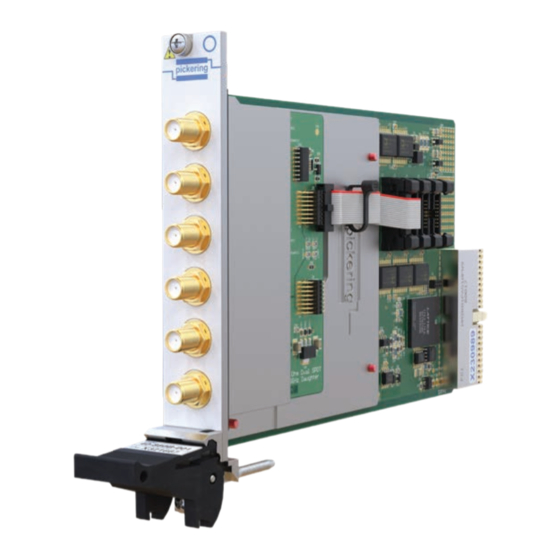
- Page 1 4x-880B User Manual PXI/PXIe 50 Ω SPDT Terminated 8 GHz RF Switches pickeringtest.com Issue 2.0, November 2023...
- Page 2 © Copyright (2023) Pickering Interfaces. All Rights Reserved. No part of this publication may be reproduced, transmitted, transcribed, translated or stored in any form, or by any means without the written permission of Pickering Interfaces. Technical details contained within this publication are subject to change without notice.
- Page 3 Pickering Interfaces strives to fulfil all relevant environmental laws and regulations and reduce wastes and releases to the environment. Pickering Interfaces aims to design and operate products in a way that protects the environment and the health and safety of its employees, customers and the public. Pickering Interfaces endeavours to develop and manufacture products that can be produced, distributed, used and recycled, or disposed of, in a safe and environmentally friendly manner.
-
Page 4: Product Safety
Product Safety Safety Symbols The following safety symbols may be used on the product and throughout the product documentation. Meaning/Description Symbol PROTECTIVE EARTH (GROUND) To identify any terminal which is intended for connection to an external conductor for protection against electric shock in case of a fault, or the terminal of a protective earth (ground) electrode. -
Page 5: Table Of Contents
Hardware Installation ..............................3.2 Software Installation ..............................3.2 Testing Operation ................................3.3 Section 4 Programming Guide .................................4.1 Programming Options for Pickering PXI/PXIe Modules ..................4.1 Relay Cycle Counting Feature Details ........................4.1 Module Architecture ..............................4.2 Programming the Module ............................4.4 Using Pickering Drivers in LabVIEW ........................4.5 Section 5 Connector Information ..............................5.1... -
Page 6: Warnings And Cautions
Unused slots in the PXI/PXIe/LXI chassis are populated with blanking plates to prevent access to user I/O signals that may be present. Blanking panels are available to order from Pickering in a variety of slot widths. If the product is not used in this manner for example by using an extender card then additional care must be taken to avoid contact with exposed signals. - Page 7 The PXI version can be and can be used to determine if a relay is approaching EOL. supported in all Pickering’s LXI Modular Switching chassis, This information could allow system connections to be revised allowing the use of a PXI or LAN controlled switching solution so that signals applied to heavily used contacts are swapped with the same high levels of performance.
- Page 8 PXI/PXIe 50 Ω SPDT Terminated 8 GHz RF Switch 4x-880B Section 1 - Technical Specification Switch 1 Switch 2 Switch 1 Switch 3 Switch 2 Switch 4 Switch 3 Quad SPDT Terminated RF Switch (Part No. 4x-880B-002) Switch 4 Switch 1 Switch 5 Switch 2 Switch 6...
- Page 9 Specifications Section 1 - Technical Specification 4x-880B Specification Mechanical Characteristics • 40-880B-001 - 1 slot 3U PXI (CompactPCI card) RF Frequency Range: 10 MHz to 8 GHz • 40-880B-002 - 2 slot 3U PXI (CompactPCI card) (useable to 8.5 GHz) •...
-
Page 10: Technical Specification
Specifications 4x-880B Section 1 - Technical Specification Insertion loss for 4x-880B-001 VSWR Channel to COM for 4x-880B-001 showing all paths up to 8.5 GHz showing all paths up to 8.5 GHz Crosstalk between banks for VSWR for internally terminated channels for 4x-880B-001 showing all paths up to 8.5 GHz 4x-880B-001 showing all paths up to 8.5 GHz Max isolation for each channel with distant path... - Page 11 42-880B-003 PXIe Octal SPDT Terminated 8 GHz RF Switch 42-880B-004 Product Customization Pickering modules are designed and manufactured on our own flexible manufacturing lines, giving complete product control and enabling simple customization to meet very specific requirements. 42-880B-001 PXIe Dual SPDT...
-
Page 12: Technical Description
Section 2 - Technical Description Functional Description A functional block diagram is provided in Figure 2.1. The module is powered by +5V and +3.3V (PXI) or +3.3V and +12V (PXIe) supplies via PCI Bus connectors mounted on the mother board. The interface to the user test equipment is via the front panel mounted SMA connectors. -
Page 13: Installation
Modular products require installation in a suitable PXI/PXIe/LXI chassis. The module is designed for indoor use only. Pre-operation Checks (Unpacking) 1. Check the module for transport damage and report any damage immediately to Pickering Interfaces. Do not attempt to install the product if any damage is evident. -
Page 14: Hardware Installation
If you are not a LabVIEW user you should choose the “full” version, and once that has been installed run the LabVIEW Runtime Engine installer via the shortcut on the Programs>>Pickering menu. In the absence of LabVIEW the Runtime Engine is required to support the Pickering Test Panels application. -
Page 15: Testing Operation
Figure 3.2 - General Soft Front Panel Icon A selector panel will appear, listing all installed Pickering PCI, PXI/PXIe or LXI switch cards and resistor cards. Click on the card you wish to control, and a graphical control panel is presented allowing operation of the card. Panels can be opened simultaneously for all the installed cards. -
Page 16: Relay Cycle Counting Feature Details
Section 4 - Programming Programming options for Pickering Interfaces PXI/PXIe Modules For information on the installation and use of drivers and the programming of Pickering’s products in various software environments, please refer to the Software User Manual. This is available as a download from: pickeringtest.com/support/software-drivers-and-downloads... -
Page 17: Module Architecture
Section 4 - Programming Module Architecture The 4x-880B is a terminated RF changeover switch available with two, four, six or eight banks. A signal path is made by activating a connection between the common terminal and channel 1 or channel 2 of the switch. The default (un-powered) state of all banks is with both channels terminated into 50Ω... - Page 18 Section 4 - Programming Depending upon the model variant, the multiplexer is treated as two, four, six or eight programming sub-unit as shown in the table below. The following page gives some simple examples using the provided drivers: the Direct I/O driver, the VISA driver and the IVI driver.
-
Page 19: Programming The Module
Once the drivers are installed the manual “Sys40Prg.pdf” and driver help files which fully describes these functions can be found in the Pickering folder(s) or the Pickering entries on your Start Menu. The card must be opened before use and closed after using the following function calls:... -
Page 20: Using Pickering Drivers In Labview
Section 4 - Programming Using Pickering Drivers In LabVIEW Most Pickering drivers include a LabVIEW wrapper to permit full operation of the Pickering product from the LabVIEW environment. These wrappers are normally installed to the current LabVIEW folder system during installation of the Pickering driver. - Page 21 Section 5 - Connectors pickering Switch 1 Switch 2 Figure 5.1 - 4x-880B-001 Dual SPDT 8GHz Switch: Connector Positions (SMA Connectors) pickeringtest.com Page 5.1...
- Page 22 Section 5 - Connectors pickering Switch 1 Switch 2 Switch 3 Switch 4 Figure 5.2 - 4x-880B-002 Quad SPDT 8GHz Switch: Connector Positions (SMA Connectors) pickeringtest.com Page 5.2...
- Page 23 Section 5 - Connectors Switch 1 pickering Switch 2 Switch 3 Switch 4 Switch 5 Switch 6 Figure 5.3 - 4x-880B-003 Hex SPDT 8GHz Switch: Connector Positions (SMA Connectors) pickeringtest.com Page 5.3...
- Page 24 Section 5 - Connectors Switch 1 Switch 2 pickering Switch 3 Switch 4 Switch 5 Switch 6 Switch 7 Switch 8 Figure 5.4 - 4x-880B-004 Octal SPDT 8GHz Switch: Connector Positions (SMA Connectors) pickeringtest.com Page 5.4...
-
Page 25: Trouble Shooting
PCI configuration, highlighting any potential configuration problems. Specific details of all installed Pickering switch cards are included. All the installed Pickering switch cards should be listed in the “Pilpxi information” section - if one or more cards is missing it may be possible to determine the reason by referring to the PCI configuration dump contained in the report, but interpretation of this information is far from straightforward, and the support@pickeringtest.com... -
Page 26: Maintenance Information
For PXI modules which are supported in one of Pickering Interfaces’ Modular LXI Chassis (such as the 60-102B and 60-103B) no module software update is required. If the module was introduced after the LXI chassis was manufactured the module may not be recognized, in this case the chassis firmware may need upgrading.
Need help?
Do you have a question about the 4 880B Series and is the answer not in the manual?
Questions and answers